US8647755B2 - Perpendicular magnetic recording medium and manufacturing method thereof - Google Patents
Perpendicular magnetic recording medium and manufacturing method thereof Download PDFInfo
- Publication number
- US8647755B2 US8647755B2 US12/150,165 US15016508A US8647755B2 US 8647755 B2 US8647755 B2 US 8647755B2 US 15016508 A US15016508 A US 15016508A US 8647755 B2 US8647755 B2 US 8647755B2
- Authority
- US
- United States
- Prior art keywords
- layer
- magnetic
- intermediate layer
- magnetic recording
- oxygen
- Prior art date
- Legal status (The legal status is an assumption and is not a legal conclusion. Google has not performed a legal analysis and makes no representation as to the accuracy of the status listed.)
- Active, expires
Links
Images


Classifications
-
- G—PHYSICS
- G11—INFORMATION STORAGE
- G11B—INFORMATION STORAGE BASED ON RELATIVE MOVEMENT BETWEEN RECORD CARRIER AND TRANSDUCER
- G11B5/00—Recording by magnetisation or demagnetisation of a record carrier; Reproducing by magnetic means; Record carriers therefor
- G11B5/84—Processes or apparatus specially adapted for manufacturing record carriers
- G11B5/8404—Processes or apparatus specially adapted for manufacturing record carriers manufacturing base layers
-
- C—CHEMISTRY; METALLURGY
- C23—COATING METALLIC MATERIAL; COATING MATERIAL WITH METALLIC MATERIAL; CHEMICAL SURFACE TREATMENT; DIFFUSION TREATMENT OF METALLIC MATERIAL; COATING BY VACUUM EVAPORATION, BY SPUTTERING, BY ION IMPLANTATION OR BY CHEMICAL VAPOUR DEPOSITION, IN GENERAL; INHIBITING CORROSION OF METALLIC MATERIAL OR INCRUSTATION IN GENERAL
- C23C—COATING METALLIC MATERIAL; COATING MATERIAL WITH METALLIC MATERIAL; SURFACE TREATMENT OF METALLIC MATERIAL BY DIFFUSION INTO THE SURFACE, BY CHEMICAL CONVERSION OR SUBSTITUTION; COATING BY VACUUM EVAPORATION, BY SPUTTERING, BY ION IMPLANTATION OR BY CHEMICAL VAPOUR DEPOSITION, IN GENERAL
- C23C14/00—Coating by vacuum evaporation, by sputtering or by ion implantation of the coating forming material
- C23C14/06—Coating by vacuum evaporation, by sputtering or by ion implantation of the coating forming material characterised by the coating material
- C23C14/14—Metallic material, boron or silicon
- C23C14/20—Metallic material, boron or silicon on organic substrates
- C23C14/205—Metallic material, boron or silicon on organic substrates by cathodic sputtering
-
- G—PHYSICS
- G11—INFORMATION STORAGE
- G11B—INFORMATION STORAGE BASED ON RELATIVE MOVEMENT BETWEEN RECORD CARRIER AND TRANSDUCER
- G11B5/00—Recording by magnetisation or demagnetisation of a record carrier; Reproducing by magnetic means; Record carriers therefor
- G11B5/62—Record carriers characterised by the selection of the material
- G11B5/64—Record carriers characterised by the selection of the material comprising only the magnetic material without bonding agent
- G11B5/66—Record carriers characterised by the selection of the material comprising only the magnetic material without bonding agent the record carriers consisting of several layers
- G11B5/672—Record carriers characterised by the selection of the material comprising only the magnetic material without bonding agent the record carriers consisting of several layers having different compositions in a plurality of magnetic layers, e.g. layer compositions having differing elemental components or differing proportions of elements
-
- G—PHYSICS
- G11—INFORMATION STORAGE
- G11B—INFORMATION STORAGE BASED ON RELATIVE MOVEMENT BETWEEN RECORD CARRIER AND TRANSDUCER
- G11B5/00—Recording by magnetisation or demagnetisation of a record carrier; Reproducing by magnetic means; Record carriers therefor
- G11B5/62—Record carriers characterised by the selection of the material
- G11B5/73—Base layers, i.e. all non-magnetic layers lying under a lowermost magnetic recording layer, e.g. including any non-magnetic layer in between a first magnetic recording layer and either an underlying substrate or a soft magnetic underlayer
- G11B5/7368—Non-polymeric layer under the lowermost magnetic recording layer
- G11B5/7369—Two or more non-magnetic underlayers, e.g. seed layers or barrier layers
- G11B5/737—Physical structure of underlayer, e.g. texture
-
- G—PHYSICS
- G11—INFORMATION STORAGE
- G11B—INFORMATION STORAGE BASED ON RELATIVE MOVEMENT BETWEEN RECORD CARRIER AND TRANSDUCER
- G11B5/00—Recording by magnetisation or demagnetisation of a record carrier; Reproducing by magnetic means; Record carriers therefor
- G11B5/62—Record carriers characterised by the selection of the material
- G11B5/73—Base layers, i.e. all non-magnetic layers lying under a lowermost magnetic recording layer, e.g. including any non-magnetic layer in between a first magnetic recording layer and either an underlying substrate or a soft magnetic underlayer
- G11B5/7368—Non-polymeric layer under the lowermost magnetic recording layer
- G11B5/7379—Seed layer, e.g. at least one non-magnetic layer is specifically adapted as a seed or seeding layer
-
- G—PHYSICS
- G11—INFORMATION STORAGE
- G11B—INFORMATION STORAGE BASED ON RELATIVE MOVEMENT BETWEEN RECORD CARRIER AND TRANSDUCER
- G11B5/00—Recording by magnetisation or demagnetisation of a record carrier; Reproducing by magnetic means; Record carriers therefor
- G11B5/84—Processes or apparatus specially adapted for manufacturing record carriers
- G11B5/851—Coating a support with a magnetic layer by sputtering
-
- Y—GENERAL TAGGING OF NEW TECHNOLOGICAL DEVELOPMENTS; GENERAL TAGGING OF CROSS-SECTIONAL TECHNOLOGIES SPANNING OVER SEVERAL SECTIONS OF THE IPC; TECHNICAL SUBJECTS COVERED BY FORMER USPC CROSS-REFERENCE ART COLLECTIONS [XRACs] AND DIGESTS
- Y10—TECHNICAL SUBJECTS COVERED BY FORMER USPC
- Y10T—TECHNICAL SUBJECTS COVERED BY FORMER US CLASSIFICATION
- Y10T428/00—Stock material or miscellaneous articles
- Y10T428/11—Magnetic recording head
Definitions
- a longitudinal recording system has been adopted in existent magnetic disk drives.
- the direction of magnetization to be recorded is in plane and adjacent magnetization is in an opposite polarity. Accordingly, a magnetization transition region is formed between adjacent recording bits for decreasing a static magnetic energy. A large width of the magnetization transition region causes an increase of the noise.
- approaches to higher recording densities of a longitudinal recording media have mainly been directed to decreasing the volume of a micro-magnet constituting a recording bit.
- the longitudinal recording medium causes a problem for the basic function of preserving recorded information due to thermal fluctuation phenomenon of magnetization along with refinement of the micro-magnet constituting the recording bit.
- perpendicular magnetic recording media have been developed mainly in recent years.
- the perpendicular recording since the direction of the recording magnetization is perpendicular to the film surface and no strong charge is present between adjacent recording bits, the width of the magnetization transition region does not increase as much as in the longitudinal medium.
- the perpendicular recording has a characteristic that the anti-magnetic field exerting between adjacent bits decreases as the recording density increases to keep the recording magnetization stable.
- a strong head magnetic field is obtained by providing a soft magnetic backing layer having a high permeability below the perpendicular recording layer, the coercivity of the perpendicular recording layer can be increased and this is one of the promising approaches for overcoming the limit of thermal demagnetization in the longitudinal recording system. Accordingly, a further increase in the density of a magnetic disk drives (HDD) is possible and application to HDD products has already been started in some fields.
- HDD magnetic disk drives
- a medium used in the perpendicular recording system mainly comprises a soft magnetic backing layer that assists a recording head, and a vertical magnetic recording layer for recording and possessing magnetic information. It is desirable to use, as the perpendicular magnetic recording layer, those materials having a strong perpendicular magnetic anisotropy such that the recording magnetization is arranged in a direction perpendicular to a film surface and in which each of magnetic particles is isolated magnetically for reducing noises.
- granular type materials comprising a Co—Cr—Pt type alloy with addition of an oxide such as SiO 2 have been studied generally. In the granular type perpendicular recording layer, since non-magnetic oxides form a grain boundary so as to surround the magnetic particle, magnetic interaction between adjacent magnetic particles is decreased.
- the perpendicular magnetic recording medium having such a fine structure has low noise property and excellent heat stability together, for which a great expectation has been placed in the improvement of the recording density.
- Patent Document 1 proposes a medium having two or more magnetic layers for a perpendicular recording layer, at least one layer being a layer comprising Co as a main ingredient, containing Pt, and containing an oxide, and at least one the other layer being a layer comprising Co as a main ingredient, containing Cr, and not containing an oxide.
- a layer constitution of the perpendicular recording layer refinement and magnetic isolation of magnetic particles are promoted and signal/noise ratio upon reading can be improved greatly.
- the thermal fluctuation resistance can be improved by improving the reverse magnetic domain nuclei forming magnetic field (—Hn) and a medium having a further excellent recording characteristic can be obtained.
- Patent Document 2 discloses a granular perpendicular recording layer comprising a Co—Cr—Pt type alloy with addition of an oxide such as SiO 2 in which the oxygen concentration on the side of the boundary with an intermediate layer is increased to higher than that on the side of the surface.
- the intermediate layer is a layer disposed below the perpendicular recording layer and responsible to the crystal orientation property of a perpendicular recording layer and formation of a model for the granular structure.
- the main point of the technique is that the degree of segregation of the oxide is different depending on the growing stage of magnetic crystal grains and segregation is promoted by increasing the oxygen concentration since segregation is more difficult in the initial stage of growing than that during growing. That is, it proposes to change the oxygen concentration contained in the magnetic layer in the direction of the film thickness.
- Patent Document 3 discloses two techniques.
- the first technique controls a gas pressure stepwise upon forming an intermediate layer in which a portion for the initial layer is formed at a low gas pressure and a surface portion is formed at a high gas pressure. It is described that the crystallinity and orientation property are ensured in the initial layer by a dense structure, the surface layer forms a more coarse structure than the initial layer, and a structure of a large crystal grain boundary width is formed so as to absorb gas molecules easily.
- an intermediate layer is formed in an atmosphere with addition of a micro-amount oxygen or nitrogen to a rare gas. Alternatively, the surface is exposed to a gas formed by adding a micro-amount of oxygen or nitrogen to the rare gas.
- this can segregate oxygen or nitrogen in the crystal grain boundary of the intermediate layer to form a formation site of a non-magnetic non-metal as a crystal grain boundary for the perpendicular recording layer formed thereon.
- oxygen is not added to a portion of the initial layer and oxygen is added to a portion of the surface layer, referring to the respective gas pressures, it is 10 mTorr (1.3 Pa) for the portion of the surface layer relative to 30 mTorr (4.0 Pa) for the portion of the initial stage layer, and the portion of the surface layer is formed at a low gas pressure (see Patent Document 3, FIG. 5).
- An object of embodiments of the present invention is to provide a perpendicular magnetic recording medium with less medium noise, excellent overwrite characteristics, and scratch resistance.
- a micro-structure of a magnetic layer 17 formed thereon can be formed in a state where no magnetic oxide region is segregated and the magnetic crystal grains are isolated.
- a gas pressure for forming the upper intermediate layer 16 b is set to 5 Pa or more and 12 Pa or less which is a region much higher compared with 0.5 Pa or more and 1 Pa for the lower Ru intermediate layer 16 a .
- a second magnetic layer 18 for facilitating magnetization reversal by lowering the oxide concentration and somewhat strengthening coupling between particles only in the magnetic layer on the side of the surface is formed to a layer above the first magnetic layer 17 as a main part.
- FIG. 1 is a cross sectional view of a perpendicular magnetic recording medium according to an example of an embodiment of the present invention.
- FIG. 2 is a view showing a target composition used upon manufacture of the perpendicular magnetic medium of FIG. 1 .
- FIG. 3 is a view showing a relation between the oxygen addition amount to a sputtering gas upon forming an upper layer Ru and Hc.
- FIG. 4 is a view showing a relation between the oxygen addition amount to a sputtering gas upon forming an upper layer Ru and overwriting.
- FIG. 5 is a view showing a relation between the oxygen addition amount to a sputtering gas upon forming an upper layer Ru and MCW.
- FIG. 6 is a view showing a relation between the oxygen addition amount to a sputtering gas upon forming an upper layer Ru and bit error rate (BER).
- FIG. 7 is a view showing a relation between the oxygen addition amount to a sputtering gas upon forming an upper layer Ru and scratch resistance.
- FIG. 8 is a view showing a relation between the film thickness of an upper magnetic layer and overwriting.
- FIG. 9 is a view showing a relation between the film thickness of an upper magnetic layer and BER.
- FIG. 10 is a view showing a relation between a gas pressure upon forming a lower layer Ru and an upper layer Ru and BER.
- FIG. 11 is a view showing a relation between accumulated numbers of media manufactured continuously, and BER.
- FIG. 12 is a view showing a central value for the magnetic property of media manufactured continuously by 30,000 sheets with addition of oxygen to Ru.
- FIG. 13 is a view showing a hysteresis loop by a magnetic property evaluation apparatus utilizing a Kerr effect.
- FIG. 14 is a view showing a relation between the accumulated numbers of continuously manufactured media and BER.
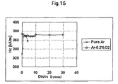
- FIG. 15 is a view showing a relation between the accumulated numbers of continuously manufactured media and Hc.
- Embodiments of the present invention relate to a perpendicular magnetic recording medium capable of recoding a great amount of information and a manufacturing method thereof.
- An object of embodiments of the present invention is to provide a perpendicular magnetic recording medium with less medium noise, excellent overwrite characteristics, and scratch resistance.
- a perpendicular magnetic recording medium comprising at least: a substrate; a soft magnetic layer formed on the substrate; a second intermediate layer formed above the soft magnetic layer and containing Ru; a third intermediate layer formed on the second intermediate layer and comprising Ru, an inevitable element, and oxygen; a first magnetic recording layer formed on the third intermediate layer and having a crystal grain boundary comprising crystal grains and an oxide; and a second magnetic recording layer formed on the first magnetic recording layer, the concentration of the oxide of the second magnetic recording layer being lower compared with that of the first magnetic recording layer; wherein the crystal grains of the first magnetic recording layer are epitaxially grown on the Ru crystal grains of the second intermediate layer.
- the method of manufacturing the perpendicular magnetic recording medium has a feature of forming a sputter target comprising Ru and inevitable elements by a sputtering method of introducing an oxygen-added Ar gas upon forming a third intermediate layer formed on the second intermediate layer and comprising Ru, inevitable element, and oxygen.
- an Ar gas pressure upon forming the second intermediate layer is 0.5 Pa or more up to 1 Pa and an oxygen concentration in the oxygen-added Ar gas introduced is 0.05% or more and 0.5% or less, and the gas pressure is 5 Pa or more and 12 Pa or less upon forming the third intermediate layer.
- An object of embodiments of the invention is to use an Ar gas with addition of a micro-amount of oxygen upon forming the third intermediate layer (upper layer Ru), whereby a micro structure of the magnetic layer formed thereon forms a state in which a non-magnetic oxide region is segregated and magnetic crystal grains are isolated.
- the gas pressure for forming the third intermediate layer in this case is set to a region of 5 Pa or more and 12 Pa or less, which is much higher compared with 0.5 Pa or more up to 1 Pa for the second intermediate layer (lower layer Ru).
- the writing performance can be improved by using a second magnetic layer in which the oxygen concentration is lowered for facilitating the magnetization reversal by somewhat strengthening the coupling between the particles in the perpendicular magnetic recording medium only on the side of the surface of the upper layer of the first magnetic layer as a main component.
- Patent Documents 2 and 3 disclose that the isolation of the magnetic crystal grains is promoted by increasing the oxygen concentration at the boundary between the intermediate layer and the magnetic layer.
- exposing the surface to oxygen before forming the magnetic film or adding oxygen only at the initial stage of growing the magnetic film has been proposed.
- oxygen is added to the upper intermediate layer per se adjacent to the magnetic layer. This can directly intake oxygen and, naturally, an oxygen excessive region can be present also on the surface.
- FIG. 1 is a cross sectional view of a perpendicular magnetic recording medium.
- FIG. 2 collectively shows as a table a composition of a sputtering target used for forming each of the layers.
- the basic layer constitution of the perpendicular magnetic recording medium in this example is as described below.
- a sputtering apparatus (C-3040) manufactured by Canon Anelba Corporation was used for forming each of the layers.
- An adhesion layer 11 comprising Al-50 at. % Ti is formed to 5 nm on a glass substrate 10 .
- an under layer soft magnetic backing layer 12 a comprising Fe-34 at. % Co-10 at.
- % Ta-5 at. % Zr is formed to 30 nm
- an anti-ferromagnetic coupling layer 13 comprising Ru is formed to 0.4 nm
- an upper soft magnetic backing layer 12 b comprising Fe-34 at. % Co-10 at. % Ta-5 at. % Zr is formed to 30 nm.
- An amorphous seed layer 14 comprising Cr-50 at. % Ti is formed to 2 nm for offsetting the crystal arrangement of the soft magnetic backing layer. Further thereover, are formed a first intermediate layer 15 comprising Ni-8 at.
- % W for controlling the crystal structure of the second intermediate layer 16 a to 7 nm, a second intermediate layer 16 a comprising Ru to 9 nm, and a third intermediate layer 16 b comprising Ru to 8 nm to form an intermediate layer comprising three layers in total.
- Above the intermediate layer are formed (Co-17 at. % Cr-18 at. % Pt) ⁇ 8 mol % SiO 2 to 13 nm as the under layer magnetic layer (first magnetic recording layer) 17 , and Co-19 at. % Cr-10 at. % Pt-3 at. % Mo to 7 nm as the upper magnetic layer (second magnetic recording layer) 18 .
- a carbon layer is formed to 4 nm as a protection lubrication layer 19 and a perfluoro alkyl polyether type material is coated further thereon.
- One of differences between the second intermediate layer 16 a comprising Ru (lower layer Ru) and the third intermediate layer 16 b (upper layer Ru) comprising Ru is a sputtering pressure upon formation.
- Ru for the second intermediate layer is formed at a low pressure of 1 Pa or less and Ru for the third intermediate layer is formed at high pressure of 5 Pa or more, respectively. It is particularly preferred for a range of 0.5 Pa or more and 1 Pa or less for Ru of the second intermediate layer and 5 Pa or more and 12 Pa or less for Ru of the third intermediate layer.
- Another difference is a presence or absence of oxygen addition to the sputtering gas. While pure Ar is used as the sputtering gas for Ru of the second intermediate layer 16 a , Ar with addition of an oxygen gas is used for Ru of the third intermediate layer.
- the first intermediate layer 15 is used for preventing disturbance of the crystal structure of the second intermediate layer 16 a formed thereon and for epitaxially growing the first magnetic recording layer 17 on the third intermediate layer 16 b.
- FIG. 3 to FIG. 6 show the change of the magnetic property and the RW property upon adding oxygen to Ru of the third intermediate layer 16 b .
- the amount of oxygen adding to the third intermediate layer 16 b was changed by the following method.
- Two systems of gas pipelines were provided in a sputtering chamber for forming the third intermediate layer.
- a pure Ar gas reservoir is connected to the first system of the pipelines and the flow rate was controlled by a first control valve.
- An Ar+10% O 2 gas reservoir is connected to the second system of the pipelines and the flow rate was controlled by a second control valve.
- the pressure in the chamber is also constant. Accordingly, when the oxygen concentration is changed, the flow rate ratio was controlled while keeping the entire gas flow rate constant.
- three types, that is, 5, 6, and 7 Pa were investigated while changing the entire gas flow rate.
- FIG. 3 is a result for examining the oxygen dependence of coercivity (Hc).
- the abscissa shows the content rate of oxygen (O 2 ) in the sputtering gas forming the third intermediate layer (upper layer Ru) 16 b
- the ordinate shows the coercivity (Hc) of the magnetic recording layer.
- FIG. 4 shows the overwrite property and this changes like the coercivity in FIG. 3 .
- the overwrite means that writing is easier toward the lower side of the graph, that is, as the numerical value increases to the negative side. The graph suggests that writing is more difficult as Hc is higher.
- FIG. 5 is a graph showing the change of MCW.
- MCW is a track width upon recording a signal, and writing to the track less extends as the width is narrower, which is suitable to high density recording. MCW changes opposite to the change of Hc or overwrite.
- FIG. 6 is a graph showing the change of BER (Bit Error Rate). Since BER represents a coefficient when the information error rate is converted into logarithm, the error rate is lower and the performance of medium is higher as the value increases to the negative side. The graph for BER changes in the same manner as in MCW in FIG. 5 . BER is most preferred at high gas pressure and when a micro-amount of oxygen is added.
- the first intermediate layer 15 and the second intermediate layer 16 a form a film of a consistent crystal structure, and BER is improved as the MCW is narrowed by adding a micro-amount of oxygen of 0.1 to 0.5% to a sputtering gas upon forming Ru of the third intermediate layer 16 b thereon. Further, it has been found that MCW is narrower and BER is improved as the gas pressure is higher upon forming the third intermediate layer.
- the lower limit pressure is substantially determined by the RW specification of: MCW ⁇ 180 nm and BER ⁇ 5.0, and the lower limit is at 5 Pa, that is studied in this case.
- the upper limit pressure the RW property is further improved along with increase in the pressure, and the upper limit cannot be defined in view of the RW property in a range up to 12.5 Pa.
- the scratch damage test is a test of colliding a magnetic head for several times to a magnetic recording medium during rotation by a ramp load to give scratch-like damages to the medium.
- the ramp load speed was set to 20 times of the speed in the actual magnetic disk apparatus.
- An HDI Reliability Tester manufactured by CENTER FOR TRIBOLOGY in USA was used. The HDI Reliability Tester is provided with an actuator for holding a magnetic recording medium and moving the magnetic head in an arcuate shape and a ramp (sliding bed) to the outside of the outer end of the magnetic recording medium.
- the HDI Reliability Tester has a control function of the magnetic head which sweeps under interlocking between the ramp and the magnetic recording medium.
- the ramp load is, for example, “load/unload mechanism” described in “Modern Storage Terminology Dictionary”, page 293, published by Nikkei BP Co.
- scratch damages on the surface of the magnetic recording medium were detected and the number of damages was counted and analyzed.
- the protective film on the magnetic recording medium was decreased in the thickness or erased, which was imaged by an ellipsometric method by a laser to calculate the number of damages by image processing.
- Candela Optical Surface Analyzer (Model 6120) manufactured by KLATENCOR Co. was used.
- evaluation was made as a circular symbol for those with the number of damages of the 30 or less, as a trigonal symbol for those with the number of damages from 30 to 50 and as a X symbol for those with the number of damages exceeding 50.
- the number of 50 or less is within a range of the specification.
- the reliability strength weakens gradually in a high gas pressure region exceeding 10 Pa, and the scratch resistance is out of the specification at 12.5 Pa to result in a practical problem. It is defined as 12 Pa or less with a view point of the reliability strength.
- the optimal oxygen concentration was 0.05% when defined at 12 Pa.
- the gas pressure upon forming the second intermediate layer (lower layer Ru) 16 a and the third intermediate layer (upper layer Ru) was investigated.
- a pure Ar gas was used for the second intermediate layer 16 a which was changed in a range from 0.5 to 5.0 Pa.
- an Ar+O 2 gas with addition of 0.2% oxygen to an Ar gas was used and it was changed in a range from 1.0 to 12.0 Pa.
- the manufactured media were put to RW evaluation and FIG. 10 shows the result of measurement for BER. In a region where the gas pressure for the under layer Ru exceeds 1.0 Pa, the BER specification ( ⁇ 5.0 or less) is not satisfied.
- the lower limit was defined as 0.5 Pa.
- the gas pressure for the upper layer Ru the BER specification is not satisfied in a region below 5.0 Pa.
- the upper limit it is 12 Pa with a view point of the reliability as shown by the result in Example 1.
- the range for the gas pressure for the second intermediate layer (lower layer Ru) 16 a is defined as 0.5 Pa or more and 1.0 Pa or less. Also when an Ar gas with addition of oxygen is used for the formation of the third intermediate layer (upper layer Ru) 16 b , it was found that the range for the gas pressure for the second intermediate layer (lower layer Ru) 16 a could provide a good RW property in a range of a lower gas pressure compared with a gas pressure range (5 Pa or more and 12 Pa or less) for the third intermediate layer (upper layer Ru) 16 b.
- FIG. 11 shows the result of measurement for BER.
- the perpendicular recording magnetic head was used for RW evaluation and the maximum recording density was measured at 1000 kfci.
- BER is not stabilized and the specification ( ⁇ 5.0 or less) is not satisfied.
- FIG. 12 shows typical magnetic properties of the magnetic recording media used for evaluation. The definition for the magnetic property is a value for a portion of a hysteresis loop measured according to Kerr effect shown in FIG. 13 .
- the magnetic recording media were produced in the same manner as described above except for producing the number of continuous production for 100,000 sheets and they were put to RW evaluation.
- FIG. 14 shows the result of evaluation. It has been found that BER was stable even at 100,000 sheets to satisfy the specification.
- FIG. 15 shows typical magnetic properties of the magnetic recording medium used for evaluation. When oxygen is added under control, the dependence of the magnetic property on the number of produced sheets decreases. It is considered that the stability contributes to the stabilization of BER.
Landscapes
- Chemical & Material Sciences (AREA)
- Engineering & Computer Science (AREA)
- Manufacturing & Machinery (AREA)
- Chemical Kinetics & Catalysis (AREA)
- Materials Engineering (AREA)
- Mechanical Engineering (AREA)
- Metallurgy (AREA)
- Organic Chemistry (AREA)
- Magnetic Record Carriers (AREA)
- Manufacturing Of Magnetic Record Carriers (AREA)
Abstract
Description
Claims (5)
Applications Claiming Priority (2)
| Application Number | Priority Date | Filing Date | Title |
|---|---|---|---|
| JP2007-117206 | 2007-04-26 | ||
| JP2007117206A JP2008276833A (en) | 2007-04-26 | 2007-04-26 | Perpendicular magnetic recording medium and manufacturing method thereof |
Publications (2)
| Publication Number | Publication Date |
|---|---|
| US20080268289A1 US20080268289A1 (en) | 2008-10-30 |
| US8647755B2 true US8647755B2 (en) | 2014-02-11 |
Family
ID=39887364
Family Applications (1)
| Application Number | Title | Priority Date | Filing Date |
|---|---|---|---|
| US12/150,165 Active 2031-11-24 US8647755B2 (en) | 2007-04-26 | 2008-04-25 | Perpendicular magnetic recording medium and manufacturing method thereof |
Country Status (2)
| Country | Link |
|---|---|
| US (1) | US8647755B2 (en) |
| JP (1) | JP2008276833A (en) |
Cited By (1)
| Publication number | Priority date | Publication date | Assignee | Title |
|---|---|---|---|---|
| US20120070692A1 (en) * | 2010-03-31 | 2012-03-22 | Wd Media (Singapore) Pte. Ltd. | Perpendicular Magnetic Disc |
Families Citing this family (9)
| Publication number | Priority date | Publication date | Assignee | Title |
|---|---|---|---|---|
| JP2009157956A (en) * | 2007-12-25 | 2009-07-16 | Hoya Corp | Method of manufacturing perpendicular magnetic recording medium |
| JP5332676B2 (en) * | 2009-02-09 | 2013-11-06 | 富士電機株式会社 | Magnetic recording medium |
| JP2011076683A (en) * | 2009-09-30 | 2011-04-14 | Wd Media Singapore Pte Ltd | Perpendicular magnetic recording medium |
| JP2011096334A (en) * | 2009-10-30 | 2011-05-12 | Wd Media Singapore Pte Ltd | Method for manufacturing perpendicular magnetic recording medium |
| JP5627223B2 (en) * | 2009-12-11 | 2014-11-19 | エイチジーエスティーネザーランドビーブイ | Perpendicular magnetic recording medium |
| JP5807944B2 (en) * | 2010-06-22 | 2015-11-10 | ダブリュディ・メディア・シンガポール・プライベートリミテッド | Method for manufacturing perpendicular magnetic recording medium |
| JP6307879B2 (en) | 2013-05-17 | 2018-04-11 | ソニー株式会社 | Magnetic recording medium and method for manufacturing the same |
| JP6083389B2 (en) * | 2014-01-07 | 2017-02-22 | ソニー株式会社 | Magnetic recording medium |
| US9990940B1 (en) * | 2014-12-30 | 2018-06-05 | WD Media, LLC | Seed structure for perpendicular magnetic recording media |
Citations (13)
| Publication number | Priority date | Publication date | Assignee | Title |
|---|---|---|---|---|
| JP2001291230A (en) | 2000-03-31 | 2001-10-19 | Sony Corp | Magnetic recording medium and method of manufacturing the same |
| US20020122960A1 (en) * | 2000-12-27 | 2002-09-05 | Showa Denko K.K. | Magnetic recording medium, production process thereof, magnetic recording and reproducing apparatus, and medium substrate |
| JP2003168207A (en) | 2001-11-29 | 2003-06-13 | Fuji Electric Co Ltd | Perpendicular magnetic recording medium and method of manufacturing perpendicular magnetic recording medium |
| JP2004022138A (en) | 2002-06-19 | 2004-01-22 | Fuji Electric Holdings Co Ltd | Perpendicular magnetic recording medium and manufacturing method thereof |
| JP2004220737A (en) | 2003-01-17 | 2004-08-05 | Fuji Electric Device Technology Co Ltd | Perpendicular magnetic recording medium and manufacturing method thereof |
| US20040185308A1 (en) * | 2003-02-07 | 2004-09-23 | Hitachi Maxell, Ltd. | Magnetic recording medium, method for producing the same, and magnetic recording apparatus |
| JP2005093040A (en) | 2003-09-22 | 2005-04-07 | Hitachi Ltd | Perpendicular magnetic recording medium and manufacturing method thereof |
| JP2005190517A (en) | 2003-12-24 | 2005-07-14 | Hitachi Global Storage Technologies Netherlands Bv | Perpendicular magnetic recording medium and magnetic storage device |
| US20060057431A1 (en) * | 2004-09-14 | 2006-03-16 | Hitachi Global Storage Technologies Netherlands B.V. | Perpendicular magnetic recording medium and manufacturing of the same |
| JP2006079718A (en) | 2004-09-09 | 2006-03-23 | Fuji Electric Device Technology Co Ltd | Perpendicular magnetic recording medium |
| US20060088737A1 (en) * | 2004-10-25 | 2006-04-27 | Hitachi Global Storage Technologies Netherlands B.V. | Perpendicular magnetic recording medium with granular structured magnetic recording layer, method for producing the same, and magnetic recording apparatus |
| US20060204791A1 (en) | 2003-04-07 | 2006-09-14 | Akira Sakawaki | Magnetic recording medium, method for producing thereof, and magnetic recording and reproducing apparatus |
| JP2006302426A (en) | 2005-04-21 | 2006-11-02 | Fuji Electric Holdings Co Ltd | Perpendicular magnetic recording medium and manufacturing method thereof |
-
2007
- 2007-04-26 JP JP2007117206A patent/JP2008276833A/en active Pending
-
2008
- 2008-04-25 US US12/150,165 patent/US8647755B2/en active Active
Patent Citations (14)
| Publication number | Priority date | Publication date | Assignee | Title |
|---|---|---|---|---|
| JP2001291230A (en) | 2000-03-31 | 2001-10-19 | Sony Corp | Magnetic recording medium and method of manufacturing the same |
| US20020122960A1 (en) * | 2000-12-27 | 2002-09-05 | Showa Denko K.K. | Magnetic recording medium, production process thereof, magnetic recording and reproducing apparatus, and medium substrate |
| JP2003168207A (en) | 2001-11-29 | 2003-06-13 | Fuji Electric Co Ltd | Perpendicular magnetic recording medium and method of manufacturing perpendicular magnetic recording medium |
| JP2004022138A (en) | 2002-06-19 | 2004-01-22 | Fuji Electric Holdings Co Ltd | Perpendicular magnetic recording medium and manufacturing method thereof |
| JP2004220737A (en) | 2003-01-17 | 2004-08-05 | Fuji Electric Device Technology Co Ltd | Perpendicular magnetic recording medium and manufacturing method thereof |
| US20040185308A1 (en) * | 2003-02-07 | 2004-09-23 | Hitachi Maxell, Ltd. | Magnetic recording medium, method for producing the same, and magnetic recording apparatus |
| US20060204791A1 (en) | 2003-04-07 | 2006-09-14 | Akira Sakawaki | Magnetic recording medium, method for producing thereof, and magnetic recording and reproducing apparatus |
| JP2005093040A (en) | 2003-09-22 | 2005-04-07 | Hitachi Ltd | Perpendicular magnetic recording medium and manufacturing method thereof |
| JP2005190517A (en) | 2003-12-24 | 2005-07-14 | Hitachi Global Storage Technologies Netherlands Bv | Perpendicular magnetic recording medium and magnetic storage device |
| JP2006079718A (en) | 2004-09-09 | 2006-03-23 | Fuji Electric Device Technology Co Ltd | Perpendicular magnetic recording medium |
| US20060057431A1 (en) * | 2004-09-14 | 2006-03-16 | Hitachi Global Storage Technologies Netherlands B.V. | Perpendicular magnetic recording medium and manufacturing of the same |
| JP2006085742A (en) | 2004-09-14 | 2006-03-30 | Hitachi Global Storage Technologies Netherlands Bv | Perpendicular magnetic recording medium and manufacturing method thereof |
| US20060088737A1 (en) * | 2004-10-25 | 2006-04-27 | Hitachi Global Storage Technologies Netherlands B.V. | Perpendicular magnetic recording medium with granular structured magnetic recording layer, method for producing the same, and magnetic recording apparatus |
| JP2006302426A (en) | 2005-04-21 | 2006-11-02 | Fuji Electric Holdings Co Ltd | Perpendicular magnetic recording medium and manufacturing method thereof |
Non-Patent Citations (1)
| Title |
|---|
| Japanese Office Action Summary from application No. 2007-117206 dated Jul. 12, 2011 (no translation). |
Cited By (2)
| Publication number | Priority date | Publication date | Assignee | Title |
|---|---|---|---|---|
| US20120070692A1 (en) * | 2010-03-31 | 2012-03-22 | Wd Media (Singapore) Pte. Ltd. | Perpendicular Magnetic Disc |
| US8865327B2 (en) * | 2010-03-31 | 2014-10-21 | Wd Media (Singapore) Pte. Ltd. | Perpendicular magnetic disc |
Also Published As
| Publication number | Publication date |
|---|---|
| US20080268289A1 (en) | 2008-10-30 |
| JP2008276833A (en) | 2008-11-13 |
Similar Documents
| Publication | Publication Date | Title |
|---|---|---|
| US8647755B2 (en) | Perpendicular magnetic recording medium and manufacturing method thereof | |
| US7060375B2 (en) | Perpendicular magnetic recording media | |
| US8771849B2 (en) | Perpendicular magnetic recording medium and magnetic recording/reproducing apparatus using the same | |
| US8390956B2 (en) | Perpendicular magnetic recording medium having FCC seed layers | |
| CN101373600B (en) | Perpendicular magnetic recording media and magnetic storage apparatus using the same | |
| CN100520919C (en) | Magnetic storage device | |
| US20090073599A1 (en) | Perpendicular magnetic recording medium and magnetic recording and reproducing apparatus using the same | |
| JP2008176858A (en) | Perpendicular magnetic recording medium and hard disk drive using the same | |
| EP1653451B1 (en) | Perpendicular magnetic recording medium | |
| JP5067744B2 (en) | Perpendicular magnetic recording medium | |
| JP5337451B2 (en) | Perpendicular magnetic recording medium | |
| US20070026260A1 (en) | Granular recording medium for perpendicular recording and recording apparatus | |
| US8705208B2 (en) | Perpendicular magnetic recording medium (PMRM) and magnetic storage device using the same | |
| US20070082414A1 (en) | Perpendicular magnetic recording medium, method for production of the same, and magnetic recording apparatus | |
| US20070042226A1 (en) | Intermediate tri-layer structure for perpendicular recording media | |
| US6858330B2 (en) | Perpendicular magnetic recording media and magnetic storage apparatus using the same | |
| SG178370A1 (en) | Magnetic recording media with reliable writability and erasure | |
| US8071228B2 (en) | Perpendicular magnetic recording medium | |
| US7457064B2 (en) | Perpendicular magnetic recording medium, method of evaluating magnetic properties of the same | |
| KR100464318B1 (en) | Magnetic recording media | |
| JP4678716B2 (en) | Perpendicular magnetic recording medium | |
| CN101258542B (en) | Magnetic recording medium and magnetic recording and reproducing device | |
| KR100935147B1 (en) | Vertical magnetic recording medium, manufacturing method thereof and magnetic recording device | |
| JP2005141825A (en) | Magnetic recording medium and magnetic recording apparatus | |
| WO2007074913A1 (en) | Magentic recording medium and magnetic recording and reproducing device |
Legal Events
| Date | Code | Title | Description |
|---|---|---|---|
| AS | Assignment |
Owner name: HITACHI GLOBAL STORAGE TECHNOLOGIES NETHERLANDS B. Free format text: ASSIGNMENT OF ASSIGNORS INTEREST;ASSIGNORS:YAMAMOTO, TOMOO;INAGAKI, JOE;SARBANOO, DAS;AND OTHERS;REEL/FRAME:021881/0256 Effective date: 20080422 |
|
| AS | Assignment |
Owner name: HGST, NETHERLANDS B.V., NETHERLANDS Free format text: CHANGE OF NAME;ASSIGNOR:HGST, NETHERLANDS B.V.;REEL/FRAME:029341/0777 Effective date: 20120723 Owner name: HGST NETHERLANDS B.V., NETHERLANDS Free format text: CHANGE OF NAME;ASSIGNOR:HITACHI GLOBAL STORAGE TECHNOLOGIES NETHERLANDS B.V.;REEL/FRAME:029341/0777 Effective date: 20120723 |
|
| FEPP | Fee payment procedure |
Free format text: PAYOR NUMBER ASSIGNED (ORIGINAL EVENT CODE: ASPN); ENTITY STATUS OF PATENT OWNER: LARGE ENTITY |
|
| STCF | Information on status: patent grant |
Free format text: PATENTED CASE |
|
| AS | Assignment |
Owner name: WESTERN DIGITAL TECHNOLOGIES, INC., CALIFORNIA Free format text: ASSIGNMENT OF ASSIGNORS INTEREST;ASSIGNOR:HGST NETHERLANDS B.V.;REEL/FRAME:040826/0821 Effective date: 20160831 |
|
| FPAY | Fee payment |
Year of fee payment: 4 |
|
| AS | Assignment |
Owner name: JPMORGAN CHASE BANK, N.A., AS AGENT, ILLINOIS Free format text: SECURITY INTEREST;ASSIGNOR:WESTERN DIGITAL TECHNOLOGIES, INC.;REEL/FRAME:052915/0566 Effective date: 20200113 |
|
| MAFP | Maintenance fee payment |
Free format text: PAYMENT OF MAINTENANCE FEE, 8TH YEAR, LARGE ENTITY (ORIGINAL EVENT CODE: M1552); ENTITY STATUS OF PATENT OWNER: LARGE ENTITY Year of fee payment: 8 |
|
| AS | Assignment |
Owner name: WESTERN DIGITAL TECHNOLOGIES, INC., CALIFORNIA Free format text: RELEASE OF SECURITY INTEREST AT REEL 052915 FRAME 0566;ASSIGNOR:JPMORGAN CHASE BANK, N.A.;REEL/FRAME:059127/0001 Effective date: 20220203 |
|
| AS | Assignment |
Owner name: JPMORGAN CHASE BANK, N.A., ILLINOIS Free format text: PATENT COLLATERAL AGREEMENT - A&R LOAN AGREEMENT;ASSIGNOR:WESTERN DIGITAL TECHNOLOGIES, INC.;REEL/FRAME:064715/0001 Effective date: 20230818 Owner name: JPMORGAN CHASE BANK, N.A., ILLINOIS Free format text: PATENT COLLATERAL AGREEMENT - DDTL LOAN AGREEMENT;ASSIGNOR:WESTERN DIGITAL TECHNOLOGIES, INC.;REEL/FRAME:067045/0156 Effective date: 20230818 |
|
| MAFP | Maintenance fee payment |
Free format text: PAYMENT OF MAINTENANCE FEE, 12TH YEAR, LARGE ENTITY (ORIGINAL EVENT CODE: M1553); ENTITY STATUS OF PATENT OWNER: LARGE ENTITY Year of fee payment: 12 |