US8636484B2 - Bellows plungers having one or more helically extending features, pumps including such bellows plungers, and related methods - Google Patents
Bellows plungers having one or more helically extending features, pumps including such bellows plungers, and related methods Download PDFInfo
- Publication number
- US8636484B2 US8636484B2 US12/684,528 US68452810A US8636484B2 US 8636484 B2 US8636484 B2 US 8636484B2 US 68452810 A US68452810 A US 68452810A US 8636484 B2 US8636484 B2 US 8636484B2
- Authority
- US
- United States
- Prior art keywords
- bellows plunger
- bellows
- tubular body
- fluid
- fluid chamber
- Prior art date
- Legal status (The legal status is an assumption and is not a legal conclusion. Google has not performed a legal analysis and makes no representation as to the accuracy of the status listed.)
- Expired - Fee Related, expires
Links
- 238000000034 method Methods 0.000 title abstract description 7
- 239000012530 fluid Substances 0.000 claims description 261
- 238000004891 communication Methods 0.000 claims description 19
- 239000000463 material Substances 0.000 claims description 10
- 238000005086 pumping Methods 0.000 claims description 4
- 229920001971 elastomer Polymers 0.000 claims description 3
- 239000000806 elastomer Substances 0.000 claims description 3
- 239000004033 plastic Substances 0.000 claims description 3
- 229920003023 plastic Polymers 0.000 claims description 3
- 229920002313 fluoropolymer Polymers 0.000 claims description 2
- 239000004811 fluoropolymer Substances 0.000 claims description 2
- 230000015572 biosynthetic process Effects 0.000 claims 1
- 239000012778 molding material Substances 0.000 abstract description 13
- 238000000465 moulding Methods 0.000 abstract 1
- 238000007789 sealing Methods 0.000 description 5
- 230000000295 complement effect Effects 0.000 description 4
- 230000007423 decrease Effects 0.000 description 4
- -1 ethylene diene Chemical class 0.000 description 4
- 230000007246 mechanism Effects 0.000 description 3
- 229920001780 ECTFE Polymers 0.000 description 2
- 239000004812 Fluorinated ethylene propylene Substances 0.000 description 2
- 239000002033 PVDF binder Substances 0.000 description 2
- 238000005452 bending Methods 0.000 description 2
- 230000008602 contraction Effects 0.000 description 2
- 238000005336 cracking Methods 0.000 description 2
- 229920000840 ethylene tetrafluoroethylene copolymer Polymers 0.000 description 2
- 239000007788 liquid Substances 0.000 description 2
- 238000004519 manufacturing process Methods 0.000 description 2
- 229920009441 perflouroethylene propylene Polymers 0.000 description 2
- 230000002093 peripheral effect Effects 0.000 description 2
- 229920002981 polyvinylidene fluoride Polymers 0.000 description 2
- 229920002943 EPDM rubber Polymers 0.000 description 1
- 239000005977 Ethylene Substances 0.000 description 1
- 229920002449 FKM Polymers 0.000 description 1
- 229920000459 Nitrile rubber Polymers 0.000 description 1
- 239000004677 Nylon Substances 0.000 description 1
- 229920001774 Perfluoroether Polymers 0.000 description 1
- 239000004698 Polyethylene Substances 0.000 description 1
- 229910000831 Steel Inorganic materials 0.000 description 1
- 239000002253 acid Substances 0.000 description 1
- 238000007792 addition Methods 0.000 description 1
- 239000000853 adhesive Substances 0.000 description 1
- 230000001070 adhesive effect Effects 0.000 description 1
- 229910010293 ceramic material Inorganic materials 0.000 description 1
- 238000010276 construction Methods 0.000 description 1
- 230000001351 cycling effect Effects 0.000 description 1
- 238000012217 deletion Methods 0.000 description 1
- 230000037430 deletion Effects 0.000 description 1
- 238000006073 displacement reaction Methods 0.000 description 1
- 229920005570 flexible polymer Polymers 0.000 description 1
- NBVXSUQYWXRMNV-UHFFFAOYSA-N fluoromethane Chemical compound FC NBVXSUQYWXRMNV-UHFFFAOYSA-N 0.000 description 1
- 238000001746 injection moulding Methods 0.000 description 1
- 239000002184 metal Substances 0.000 description 1
- 229910001092 metal group alloy Inorganic materials 0.000 description 1
- 238000012986 modification Methods 0.000 description 1
- 230000004048 modification Effects 0.000 description 1
- 150000002825 nitriles Chemical class 0.000 description 1
- 229920001778 nylon Polymers 0.000 description 1
- 239000003921 oil Substances 0.000 description 1
- 229920001084 poly(chloroprene) Polymers 0.000 description 1
- 229920000573 polyethylene Polymers 0.000 description 1
- 239000002861 polymer material Substances 0.000 description 1
- 229920002635 polyurethane Polymers 0.000 description 1
- 239000004814 polyurethane Substances 0.000 description 1
- 230000010349 pulsation Effects 0.000 description 1
- 230000002787 reinforcement Effects 0.000 description 1
- 239000011347 resin Substances 0.000 description 1
- 229920005989 resin Polymers 0.000 description 1
- 229920003031 santoprene Polymers 0.000 description 1
- 230000011664 signaling Effects 0.000 description 1
- 239000010935 stainless steel Substances 0.000 description 1
- 229910001220 stainless steel Inorganic materials 0.000 description 1
- 239000010959 steel Substances 0.000 description 1
- 239000000126 substance Substances 0.000 description 1
- 239000012815 thermoplastic material Substances 0.000 description 1
- XLYOFNOQVPJJNP-UHFFFAOYSA-N water Substances O XLYOFNOQVPJJNP-UHFFFAOYSA-N 0.000 description 1
Images


Classifications
-
- F—MECHANICAL ENGINEERING; LIGHTING; HEATING; WEAPONS; BLASTING
- F04—POSITIVE - DISPLACEMENT MACHINES FOR LIQUIDS; PUMPS FOR LIQUIDS OR ELASTIC FLUIDS
- F04B—POSITIVE-DISPLACEMENT MACHINES FOR LIQUIDS; PUMPS
- F04B9/00—Piston machines or pumps characterised by the driving or driven means to or from their working members
- F04B9/08—Piston machines or pumps characterised by the driving or driven means to or from their working members the means being fluid
- F04B9/12—Piston machines or pumps characterised by the driving or driven means to or from their working members the means being fluid the fluid being elastic, e.g. steam or air
- F04B9/129—Piston machines or pumps characterised by the driving or driven means to or from their working members the means being fluid the fluid being elastic, e.g. steam or air having plural pumping chambers
- F04B9/131—Piston machines or pumps characterised by the driving or driven means to or from their working members the means being fluid the fluid being elastic, e.g. steam or air having plural pumping chambers with two mechanically connected pumping members
- F04B9/135—Piston machines or pumps characterised by the driving or driven means to or from their working members the means being fluid the fluid being elastic, e.g. steam or air having plural pumping chambers with two mechanically connected pumping members reciprocating movement of the pumping members being obtained by two single-acting elastic-fluid motors, each acting in one direction
-
- F—MECHANICAL ENGINEERING; LIGHTING; HEATING; WEAPONS; BLASTING
- F04—POSITIVE - DISPLACEMENT MACHINES FOR LIQUIDS; PUMPS FOR LIQUIDS OR ELASTIC FLUIDS
- F04B—POSITIVE-DISPLACEMENT MACHINES FOR LIQUIDS; PUMPS
- F04B43/00—Machines, pumps, or pumping installations having flexible working members
- F04B43/0009—Special features
- F04B43/0054—Special features particularities of the flexible members
-
- F—MECHANICAL ENGINEERING; LIGHTING; HEATING; WEAPONS; BLASTING
- F04—POSITIVE - DISPLACEMENT MACHINES FOR LIQUIDS; PUMPS FOR LIQUIDS OR ELASTIC FLUIDS
- F04B—POSITIVE-DISPLACEMENT MACHINES FOR LIQUIDS; PUMPS
- F04B43/00—Machines, pumps, or pumping installations having flexible working members
- F04B43/02—Machines, pumps, or pumping installations having flexible working members having plate-like flexible members, e.g. diaphragms
- F04B43/06—Pumps having fluid drive
- F04B43/073—Pumps having fluid drive the actuating fluid being controlled by at least one valve
- F04B43/0736—Pumps having fluid drive the actuating fluid being controlled by at least one valve with two or more pumping chambers in parallel
-
- F—MECHANICAL ENGINEERING; LIGHTING; HEATING; WEAPONS; BLASTING
- F04—POSITIVE - DISPLACEMENT MACHINES FOR LIQUIDS; PUMPS FOR LIQUIDS OR ELASTIC FLUIDS
- F04B—POSITIVE-DISPLACEMENT MACHINES FOR LIQUIDS; PUMPS
- F04B43/00—Machines, pumps, or pumping installations having flexible working members
- F04B43/08—Machines, pumps, or pumping installations having flexible working members having tubular flexible members
- F04B43/10—Pumps having fluid drive
- F04B43/113—Pumps having fluid drive the actuating fluid being controlled by at least one valve
- F04B43/1136—Pumps having fluid drive the actuating fluid being controlled by at least one valve with two or more pumping chambers in parallel
Definitions
- the present invention relates generally to positive displacement devices. More particularly, embodiments of the present invention relate to bellows plungers for use in reciprocating devices (e.g., pumps, valves, etc.), reciprocating pumps including such bellows plungers, and to methods of forming bellows plungers.
- reciprocating devices e.g., pumps, valves, etc.
- Reciprocating fluid pumps are used in many industries. Reciprocating fluid pumps generally include two fluid chambers in a pump body. A reciprocating piston or shaft is driven back and forth within the pump body. One or more diaphragms or bellows plungers may be connected to the reciprocating piston or shaft. As the reciprocating piston moves in one direction, the movement of the diaphragms or bellows plungers results in fluid being drawn into a first fluid chamber of the two fluid chambers and expelled from the second chamber. As the reciprocating piston moves in the opposite direction, the movement of the diaphragms or bellows plungers results in fluid being expelled from the first chamber and drawn into the second chamber.
- a chamber inlet and a chamber outlet may be provided in fluid communication with the first fluid chamber, and another chamber inlet and another chamber outlet may be provided in fluid communication with the second fluid chamber.
- the chamber inlets to the first and second fluid chambers may be in fluid communication with a common single pump inlet, and the chamber outlets from the first and second fluid chambers may be in fluid communication with a common single pump outlet, such that fluid may be drawn into the pump through the pump inlet from a single fluid source, and fluid may be expelled from the pump through a single pump outlet.
- Check valves may be provided at the chamber inlet and outlet of each of the fluid chambers to ensure that fluid can only flow into the fluid chambers through the chamber inlets, and fluid can only flow out of the of the fluid chambers through the chamber outlets.
- the present invention includes bellows plungers having a tubular body.
- the tubular body includes a side wall having a shape defining at least one ridge extending continuously and helically about a longitudinal axis of the tubular body from a location proximate a first closed end of the body to a location proximate an opposite, second open end of the body.
- the present invention includes reciprocating fluid pumps for pumping a subject fluid.
- the pumps include a pump body, at least one subject fluid chamber within the pump body, and at least one bellows plunger located at least partially within the pump body.
- a surface of the bellows plunger defines a surface of the subject fluid chamber.
- the bellows plunger comprises a tubular body that includes a side wall having a shape defining at least one ridge extending continuously and helically about a longitudinal axis of the tubular body from a location proximate a first closed end of the body to a location proximate an opposite, second open end of the body.
- the present invention includes methods of forming bellows plungers in which a space between an outer surface of a mold core and an inner surface of a mold is filled with a molding material, and the molding material is solidified within the space to form a bellows plunger having a tubular body that includes a side wall having a shape defining at least one ridge extending continuously and helically about a longitudinal axis of the tubular body from a location proximate a first end of the tubular body to a location proximate a second end of the tubular body.
- the outer surface of the mold core may comprise at least one helically extending ridge
- the inner surface of the mold may comprise a helically extending recess complementary to and aligned with the helically extending ridge of the outer surface of the mold core to form the tubular body of the bellows plunger.
- FIG. 1 is a cross-sectional view of an example of an embodiment of a reciprocating fluid pump of the present invention, which includes bellows plungers having helically extending features.
- FIG. 2 is an enlarged view of a portion of FIG. 1 illustrating a shift piston of the fluid pump
- FIG. 3 is an enlarged view of another portion of FIG. 1 illustrating a shuttle valve of the fluid pump
- FIG. 4 is an isometric view of a bellows plunger of the reciprocating fluid pump shown in FIG. 1 .
- FIG. 5 is a side elevation view of the bellows plunger shown in FIGS. 1 and 4 .
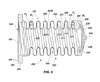
- FIG. 6 is a longitudinal cross-sectional view of the bellows plunger shown in FIGS. 1 , 4 , and 5 .
- FIG. 7 is a cross-sectional view of an assembled mold assembly that may be used to form a bellows plunger in accordance with additional embodiments of the present invention.
- FIG. 8 is an exploded view of the mold assembly of FIG. 7 and a bellows plunger that has been molded therein, wherein the bellows plunger and a mold core are illustrated in cross-sectional views.
- FIG. 9 is a longitudinal cross-sectional view, similar to that of FIG. 6 , illustrating another embodiment of a bellows plunger of the present invention.
- FIG. 10 is a longitudinal cross-sectional view, similar to those of FIGS. 6 and 9 , illustrating yet another embodiment of a bellows plunger of the present invention.
- FIGS. 11 through 13 illustrate cross-sectional views of portions of side walls of additional embodiments of bellows plungers of the present invention.
- FIG. 1 illustrates an embodiment of a fluid pump 100 of the present invention.
- the fluid pump is configured to pump a subject fluid, such as, for example, a liquid (e.g., water, oil, acid, etc.) gas, or powdered substance, using a pressurized drive fluid such as, for example, compressed gas (e.g., air).
- a subject fluid such as, for example, a liquid (e.g., water, oil, acid, etc.) gas, or powdered substance
- a pressurized drive fluid such as, for example, compressed gas (e.g., air).
- the fluid pump 100 may comprise a pneumatically operated liquid pump.
- the fluid pump 100 may comprise a reciprocating pump.
- the fluid pump 100 includes a pump body 102 , which may comprise two or more components that may be assembled together to form the pump body 102 .
- the pump body 102 may include therein a first cavity 110 and a second cavity 112 .
- a drive shaft 116 may be positioned within the pump body 102 and extend between the first cavity 110 and the second cavity 112 .
- a first end of the drive shaft 116 may be positioned within the first cavity 110
- an opposite, second end of the drive shaft 116 may be positioned within the second cavity 112 .
- the drive shaft 116 is configured to slide back and forth within pump body 102 .
- a fluid tight seal may be provided between a central portion of the drive shaft 116 and the pump body 102 , such that fluid is prevented from flowing through any space between the drive shaft 116 and the pump body 102 between the first cavity 110 and the second cavity 112 .
- a first bellows plunger 120 may be disposed within the first cavity 110
- a second bellows plunger 122 may be disposed within the second cavity 112 .
- the bellows plungers 120 , 122 may each be formed of and comprise a flexible polymer material (e.g., an elastomer or a thermoplastic material).
- each of the bellows plungers 120 , 122 may comprise one or more helically extending features (e.g., flutes) that enable the body of the bellows plungers 120 , 122 to be longitudinally extended and compressed as the fluid pump 100 is cycled.
- the first bellows plunger 120 may divide the first cavity 110 into a first subject fluid chamber 126 on a side of the first bellows plunger 120 opposite the drive shaft 116 and a first drive fluid chamber 127 on a side of the first bellows plunger 120 proximate the drive shaft 116 .
- the second bellows plunger 122 may divide the second cavity 112 into a second subject fluid chamber 128 on a side of the second bellows plunger 122 opposite the drive shaft 116 and a second drive fluid chamber 129 on a side of the second bellows plunger 122 proximate the drive shaft 116 .
- a peripheral edge of the first bellows plunger 120 may be attached to the pump body 102 , and a fluid tight seal may be provided between the pump body 102 and the first bellows plunger 120 .
- the first end of the drive shaft 116 may, optionally, be coupled to the first bellows plunger 120 .
- the first end of the drive shaft 116 may extend through an aperture in the first bellows plunger 120 , and sealing attachment members (e.g., nuts, washers, seals, etc.) may be provided on the drive shaft 116 on both sides of the first bellows plunger 120 to attach the first bellows plunger 120 to the first end of the drive shaft 116 , and to provide a fluid tight seal between the drive shaft 116 and the first bellows plunger 120 , such that fluid cannot flow between the first subject fluid chamber 126 and the first drive fluid chamber 127 through any space between the drive shaft 116 and the first bellows plunger 120 .
- sealing attachment members e.g., nuts, washers, seals, etc.
- a peripheral edge of the second bellows plunger 122 may be attached to the pump body 102 , and a fluid tight seal may be provided between the pump body 102 and the second bellows plunger 122 .
- the second end of the drive shaft 116 may be coupled to the second bellows plunger 122 .
- the second end of the drive shaft 116 may extend through an aperture in the second bellows plunger 122 , and sealing attachment members (e.g., nuts, washers, seals, etc.) may be provided on the drive shaft 116 on both sides of the second bellows plunger 122 to attach the second bellows plunger 122 to the second end of the drive shaft 116 , and to provide a fluid tight seal between the drive shaft 116 and the second bellows plunger 122 , such that fluid cannot flow between the second subject fluid chamber 128 and the second drive fluid chamber 129 through any space between the drive shaft 116 and the second bellows plunger 122 .
- sealing attachment members e.g., nuts, washers, seals, etc.
- the drive shaft 116 is capable of sliding back and forth within the pump body 102 .
- the first bellows plunger 120 will be caused to move such that the volume of the first subject fluid chamber 126 increases and the volume of the first drive fluid chamber 127 decreases
- the second bellows plunger 122 will be caused to move such that the volume of the second subject fluid chamber 128 decreases and the volume of the second drive fluid chamber 129 increases.
- the drive shaft 116 moves to the left (from the perspective of FIG.
- the first bellows plunger 120 will be caused to move such that the volume of the first subject fluid chamber 126 decreases and the volume of the first drive fluid chamber 127 increases, and the second bellows plunger 122 will be caused to move such that the volume of the second subject fluid chamber 128 increases and the volume of the second drive fluid chamber 129 decreases.
- a first subject fluid inlet 130 may be provided in the pump body 102 that leads into the first subject fluid chamber 126 through the pump body 102
- a first subject fluid outlet 134 may be provided in the pump body 102 that leads out from the first subject fluid chamber 126 through the pump body 102
- a second subject fluid inlet 132 may be provided in the pump body 102 that leads into the second subject fluid chamber 128 through the pump body 102
- a second subject fluid outlet 136 may be provided in the pump body 102 that leads out from the second subject fluid chamber 128 through the pump body 102 .
- a first subject fluid inlet check valve 131 may be provided proximate the first subject fluid inlet 130 to ensure that fluid is capable of flowing into the first subject fluid chamber 126 through the first subject fluid inlet 130 , but incapable of flowing out from the first subject fluid chamber 126 through the first subject fluid inlet 130 .
- a first subject fluid outlet check valve 135 may be provided proximate the first subject fluid outlet 134 to ensure that fluid is capable of flowing out from the first subject fluid chamber 126 through the first subject fluid outlet 134 , but incapable of flowing into the first subject fluid chamber 126 through the first subject fluid outlet 134 .
- a second subject fluid inlet check valve 133 may be provided proximate the second subject fluid inlet 132 to ensure that fluid is capable of flowing into the second subject fluid chamber 128 through the second subject fluid inlet 132 , but incapable of flowing out from the second subject fluid chamber 128 through the second subject fluid inlet 132 .
- a second subject fluid outlet check valve 137 may be provided proximate the second subject fluid outlet 136 to ensure that fluid is capable of flowing out from the second subject fluid chamber 128 through the second subject fluid outlet 136 , but incapable of flowing into the second subject fluid chamber 128 through the second subject fluid outlet 136 .
- the subject fluid inlets 130 , 132 leading to the first subject fluid chamber 126 and the second subject fluid chamber 128 may be in fluid communication with a common fluid inlet line or conduit, and the subject fluid outlets 134 , 136 leading out from the first subject fluid chamber 126 and the second subject fluid chamber 128 may be in fluid communication with a common fluid outlet line or conduit, such that fluid may be drawn into the fluid pump 100 through the fluid inlet line from a single fluid source, and fluid may be expelled from the fluid pump 100 through a single fluid outlet line.
- the first drive fluid chamber 127 may be pressurized with pressurized drive fluid, which will push the first bellows plunger 120 to the left (from the perspective of FIG. 1 ).
- the drive shaft 116 and the second bellows plunger 122 are also pulled and/or pushed to the left.
- any subject fluid within the first subject fluid chamber 126 will be expelled from the first subject fluid chamber 126 through the first subject fluid outlet 134 , and subject fluid will be drawn into the second subject fluid chamber 128 through the second subject fluid inlet 132 .
- the second drive fluid chamber 129 may be pressurized with pressurized drive fluid, which will push the second bellows plunger 122 to the right (from the perspective of FIG. 1 ).
- the drive shaft 116 and the first bellows plunger 120 also may be pushed and/or pulled to the right.
- any subject fluid within the second subject fluid chamber 128 will be expelled from the second subject fluid chamber 128 through the second subject fluid outlet 136 , and subject fluid will be drawn into the first subject fluid chamber 126 through the first subject fluid inlet 130 .
- the first drive fluid chamber 127 and the second drive fluid chamber 129 may be pressurized in an alternating manner to cause the drive shaft 116 , the first bellows plunger 120 , and the second bellows plunger 122 to reciprocate back and forth within the pump body 102 , as discussed above.
- the fluid pump 100 may comprise a shifting mechanism for shifting the flow of pressurized drive fluid back and forth between the first drive fluid chamber 127 and the second drive fluid chamber 129 at the ends of the stroke of the drive shaft 116 .
- the shifting mechanism may comprise, for example, one or more shift pistons 140 , 142 and a shuttle valve 170 , as discussed in further detail below.
- a first shift piston 140 may be disposed within the pump body 102 proximate and adjacent the first bellows plunger 120
- a second shift piston 142 may be disposed within the pump body 102 proximate and adjacent the second bellows plunger 122
- Each of the shift pistons 140 , 142 may comprise an elongated, generally cylindrical body that is oriented generally parallel to the drive shaft 116 .
- the shift pistons 140 , 142 may be located within the pump body 102 beside the drive shaft 116 .
- the shift pistons 140 , 142 may be disposed within respective generally cylindrical bores that are located between the first drive fluid chamber 127 and the second drive fluid chamber 129 and that that extend through the pump body 102 .
- FIG. 2 is an enlarged view of a portion of FIG. 1 including the first shift piston 140 .
- two recesses 143 A, 143 B may be provided in a wall of the pump body 102 within the bore extending through the pump body 102 in which the first shift piston 140 is disposed.
- Each of the two recesses 143 A, 143 B may comprise a substantially continuous annular recess that extends around the bore in the pump body 102 in which the first shift piston 140 is disposed.
- a fluid conduit may lead through the pump body 102 to each of the two recesses 143 A, 143 B, respectively.
- a first shift-shuttle conduit 146 A may extend between the first recess 143 A, and the shuttle valve 170 .
- a first shift piston vent conduit 148 A may extend from the second recess 143 B to the exterior of the pump body 102 .
- a second shift-shuttle conduit 146 B may extend between the second shift piston 142 and the shuttle valve 170 in a manner like that of the first shift-shuttle conduit 146 A
- a second shift piston vent conduit 148 B may extend from the second shift piston 142 to the exterior of the pump body 102 in a manner like that of the first shift piston vent conduit 148 A, as shown in FIG. 1 .
- a cylindrical insert 150 may be disposed between the shift piston 140 and the two recesses 143 A, 143 B in the wall of the pump body 102 within the bore in which the shift piston 140 is disposed.
- One or more holes 152 may be provided through the cylindrical insert 150 in each plane transverse to the longitudinal axis of the shift piston 140 that is aligned with one of the two recesses 143 A, 143 B.
- fluid communication is provided between the interior of the cylindrical insert 150 and each of the recesses 143 A, 143 B through the holes 152 in the cylindrical insert 150 .
- annular sealing members e.g., O-rings
- O-rings optionally may be provided between the outer cylindrical surface of the cylindrical insert 150 and the adjacent wall of the of the pump body 102 within the bore in which the shift piston 140 is disposed to eliminate fluid communication between the recesses 143 A, 143 B through any space between the cylindrical insert 150 and the pump body 102 .
- the shift piston 140 comprises an annular recess 156 in the outer surface of the shift piston 140 .
- the annular recess 156 is located on the shift piston 140 , and has a length (i.e., a dimension generally parallel to the longitudinal axis of the shift piston 140 ) that is sufficiently long, to cause the annular recess 156 to longitudinally overlap the second recess 143 B throughout the stroke of the shift piston 140 .
- fluid communication is provided between the space surrounding the shift piston 140 within the annular recess 156 and the exterior of the pump body 102 through the second recess 143 B and the corresponding hole 152 in the cylindrical insert 150 that is aligned with the second recess 143 B, which may facilitate movement of the shift piston 140 within the pump body 102 .
- an elongated extension 160 may be provided on a first end of the shift piston 140 that extends at least partially into the first drive fluid chamber 127 ( FIG. 1 ).
- a space 162 within the pump body 102 adjacent an end surface 164 of an opposite, second end of the shift piston 140 may be in fluid communication with the first drive chamber 127 and a first drive chamber conduit 180 A that extends between the first drive chamber 127 and the shuttle valve 170 , as shown in FIG. 1 .
- a second drive chamber conduit 180 B may similarly extend between a space within the pump body adjacent an end surface of the second shift piston 142 and the shuttle valve 170 , as shown in FIG. 1 .
- the elongated extension 160 of the shift piston 140 may be located and configured such that the first bellows plunger 120 abuts against the end of the elongated extension 160 of the shift piston 140 .
- the fluid communication provided between the first drive fluid chamber 127 and the space 162 adjacent the end surface 164 of the second end of the shift piston 140 may force the end of the elongated extension 160 of the shift piston 140 against the first bellows plunger 120 , and force the shift piston 140 to also move to the left.
- the first bellows plunger 120 When the first bellows plunger 120 is moving to the right (from the perspectives of FIGS. 1 and 2 ) due to pressurization of the second drive fluid chamber 129 , the first bellows plunger 120 will also be forced against the end of the elongated extension 160 of the shift piston 140 and will force the shift piston 140 to also move to the right.
- fluid communication will be provided between the first drive chamber conduit 180 A and the first shift-shuttle conduit 146 A through the space 162 adjacent the end surface 164 of the shift piston 140 , which will send pressurized air (or other drive fluid) through the first shift-shuttle conduit 146 A to the shuttle valve 170 , signaling the end of a stroke of the drive shaft 116 and causing the drive shaft 116 , the first bellows plunger 120 , and the second bellows plunger 122 to begin moving to the right (from the perspectives of FIGS. 1 and 2 ), as discussed in further detail below.
- FIG. 3 is an enlarged view of a portion of FIG. 1 including the shuttle valve 170 .
- the shuttle valve 170 includes a shuttle valve body 172 , and a shuttle spool 174 disposed within a bore extending at least partially through the shuttle valve body 172 .
- Five recesses 176 A- 176 E may be provided in a wall of the shuttle valve body 172 within the bore in which the shuttle spool 174 is located.
- Each of the five recesses 172 A- 172 E may comprise a substantially continuous annular recess that extends around the bore in the shuttle valve body 172 in which the shuttle spool 174 is disposed.
- each of the five recesses 176 A- 176 E can be seen in the cross-sectional view of FIG. 3 on the left and right sides of the shuttle spool 174 (from the perspective of FIG. 3 ).
- a fluid conduit may lead through the shuttle valve body 172 to each of the five recesses 176 A- 176 E, respectively.
- a drive fluid conduit 178 may lead to the middle, third recess 176 C, as shown in FIG. 3 .
- a pressurized drive fluid may be supplied to the third recess 176 C from a pressurized source of drive fluid (e.g., a source of compressed gas, such as compressed air).
- a pressurized source of drive fluid e.g., a source of compressed gas, such as compressed air.
- the first drive chamber conduit 180 A may extend between the second recess 176 B and the first drive fluid chamber 127
- a second drive chamber conduit 180 B may extend between the fourth recess 176 D and the second drive fluid chamber 129 .
- a first shuttle valve vent conduit 182 A may extend from the first recess 176 A to the exterior of the shuttle valve body 172
- a second shuttle valve vent conduit 182 B may extend from the fifth recess 176 E to the exterior of the shuttle valve body 172 .
- These shuttle valve vent conduits 182 A, 182 B are illustrated in FIG. 3 as threaded receptacles. Mufflers or other fluid conduits optionally may be coupled to the shuttle valve vent conduits 182 A, 182 B by way of such threaded receptacles.
- the first shift-shuttle conduit 146 A (previously described with reference to FIGS. 1 and 2 ) may extend between the first recess 143 A adjacent the first shift piston 140 ( FIG. 2 ) and a first longitudinal end of the bore in the shuttle valve body 172 in which the shuttle spool 174 is disposed
- the second shift-shuttle conduit 146 B may extend between a similar recess adjacent the second shift piston 142 ( FIG. 1 ) and an opposite, second longitudinal end of the bore in the shuttle valve body 172 in which the shuttle spool 174 is disposed.
- a cylindrical insert 190 may be disposed between the shuttle spool 174 and the five recesses 176 A- 176 E in the wall of the shuttle valve body 172 within the bore in which the shuttle spool 174 is disposed.
- the cylindrical insert 190 may comprise one or more holes 192 that extend through the cylindrical insert 190 in each plane transverse to the longitudinal axis of the shuttle spool 174 that is aligned with one of the five recesses 176 A- 176 E.
- fluid communication is provided between the interior of the cylindrical insert 190 and each of the recesses 176 A- 176 E through the holes 192 in the cylindrical insert 190 .
- annular sealing members e.g., O-rings
- O-rings optionally may be provided between the outer cylindrical surface of the cylindrical insert 190 and the adjacent wall of the shuttle valve body 172 within the bore in which the cylindrical insert 190 is disposed to eliminate fluid communication between any of the recesses 176 A- 176 E through any space between the cylindrical insert 190 and the shuttle valve body 172 .
- the shuttle spool 174 comprises a first annular recess 196 A in the outer surface of the shuttle spool 174 and a second annular recess 196 B in the outer surface of the shuttle spool 174 .
- the first annular recess 196 A and the second annular recess 196 B are separated by a central annular ridge 197 on the outer surface of the shuttle spool 174 .
- annular first end ridge 198 A is provided on the outer surface of the shuttle spool 174 on a longitudinal side of the first annular recess 196 A opposite the central annular ridge 197
- annular second end ridge 198 B is provided on the outer surface of the shuttle spool 174 on a longitudinal side of the second annular recess 196 B opposite the central annular ridge 197 .
- Each of the first annular recess 196 A and the second annular recess 196 B have a length (i.e., a dimension generally parallel to the longitudinal axis of the shuttle spool 174 ) that is long enough to at least partially longitudinally overlap two adjacent recesses of the five recesses 176 A- 176 E.
- the first annular recess 196 A extends to and at least partially overlaps with each of the second recess 176 B and the third recess 176 C
- the second annular recess 196 B extends to and at least partially overlaps with each of the fourth recess 176 D and the fifth recess 176 E.
- fluid communication is provided between the drive fluid conduit 178 and the first drive chamber conduit 180 A through the third recess 176 C, the holes 192 in the cylindrical insert 190 aligned with the third recess 176 C, the first annular recess 196 A in the shuttle spool 174 , the holes 192 in the cylindrical insert 190 aligned with the second recess 176 B, and the second recess 176 B.
- fluid communication is provided between the second drive chamber conduit 180 B and the second shuttle valve vent conduit 182 B through the fourth recess 176 D, the holes 192 in the cylindrical insert 190 aligned with the fourth recess 176 D, the second annular recess 196 B in the shuttle spool 174 , the holes 192 in the cylindrical insert 190 aligned with the fifth recess 176 E, and the fifth recess 176 E.
- the shuttle spool 174 may be moved to the position shown in FIG. 3 by applying a pressurized drive fluid through the shuttle valve 170 from the drive fluid conduit 178 to the second drive chamber conduit 180 B, through the second drive fluid chamber 129 , and through the second shift-shuttle conduit 146 B to the second end of the shuttle spool 174 .
- the shuttle spool 174 is moved back and forth within the shuttle valve body 172 by applying positive pressure to one longitudinal end surface of the shuttle spool 174 while ambient (atmospheric) pressure is provided to the opposite longitudinal end surface of the shuttle spool 174 .
- ambient (atmospheric) pressure is provided to the opposite longitudinal end surface of the shuttle spool 174 .
- any fluid e.g., a gas, such as air
- any fluid adjacent the first end of the shuttle spool 174 and within the first shift-shuttle conduit 146 A may be vented to ambient pressure through the second shuttle valve vent conduit 182 B.
- the shuttle spool 174 may be maintained in the position shown in FIG. 3 by maintaining the positive pressure at the second end of the shuttle spool 174 (and within the second shift-shuttle conduit 146 B), and/or by using one or more detent mechanisms.
- a cycle of the fluid pump 100 begins while the shuttle spool 174 of the shuttle valve 170 is in the position shown in FIGS. 1 and 3 .
- pressurized drive fluid passes from the drive fluid conduit 178 ( FIGS. 1 and 3 ), around the shuttle spool 174 within the first annular recess 196 A therein and into the first drive chamber conduit 180 A.
- the pressurized drive fluid flows through the first drive chamber conduit 180 A to the first drive fluid chamber 127 ( FIG. 1 ), which urges the first bellows plunger 120 to the left (from the perspective of FIG. 1 ).
- first bellows plunger 120 moves to the left
- the drive shaft 116 and the second bellows plunger 122 are also pulled and/or pushed to the left.
- subject fluid within the first subject fluid chamber 126 is forced out from the first subject fluid chamber 126 through the first subject fluid outlet 134 leading out from the first subject fluid chamber 126
- subject fluid is drawn into the second subject fluid chamber 128 through the second subject fluid inlet 132 leading to the second subject fluid chamber 128 .
- the first shift piston 140 is urged to the left by the pressurized drive fluid within the space 162 ( FIG. 2 ), and the second shift piston 142 is urged to the left by the second bellows plunger 122 .
- This leftward stoke continues until the first shift piston 140 is moved far enough to the left to allow pressurized drive fluid within the space 162 ( FIG. 2 ) to pass into the first shift-shuttle conduit 146 A.
- a pulse of pressurized drive fluid flows through the first shift-shuttle conduit 146 A to the first end of the shuttle spool 174 within the shuttle valve 170 , which will cause the shuttle spool 174 to slide within the shuttle valve body 172 (i.e., toward the top of the shuttle valve 170 from the perspective of FIGS. 1 and 3 ).
- the shuttle spool 174 is not illustrated in the drawing Figures as being positioned at the opposite end of the bore within the shuttle valve body 172 , it will be appreciated that, when the shuttle spool 174 is moved to the opposite end of the bore within the shuttle valve body 172 , the pressurized drive fluid entering the shuttle valve 170 through the drive fluid conduit 178 will be diverted from the first drive chamber conduit 180 A to the second drive chamber conduit 180 B. In other words, upon movement of the shuttle spool 174 to the opposite end of the shuttle valve body 172 , pressurized drive fluid will pass from the drive fluid conduit 178 , through the second annular recess 196 B in the shuttle spool 174 , and through the second drive chamber conduit 180 B to the second drive fluid chamber 129 ( FIG.
- each of the bellows plungers 120 , 122 may comprise one or more helically extending features (e.g., flutes) that enable the body of the bellows plungers 120 , 122 to be longitudinally extended and compressed as the fluid pump 100 is cycled.
- features e.g., flutes
- FIGS. 4 through 6 illustrate the bellows plunger 120 (and the bellows plunger 122 ) of FIG. 1 .
- the bellows plunger 120 may comprise a body 200 having a first closed end 202 and an opposite, second open end 204 .
- the body 200 of the bellows plunger 120 may be generally tubular.
- the body 200 may include a generally tubular side wall 206 having an inner surface 207 A and an outer surface 207 B.
- the generally tubular side wall 206 undulates longitudinally to define a plurality of peaks 208 and valleys 210 on the exterior of the body 200 of the bellows plunger 120 .
- the peaks 208 and valleys 210 may be defined by and comprise one or more helically extending ridges 220 and one or more helically extending recesses 222 that extend helically about the bellows plunger 120 in the longitudinal direction between the first closed end 202 and the second open end 204 of the body 200 of the bellows plunger 120 .
- an average wall thickness of the body 200 may be relatively small compared to the distance between the peaks 208 and the valleys 210 .
- the peaks 208 on the outer surface 207 B of the body 200 may define corresponding valleys 212 on the inner surface 207 A of the body 200
- the valleys 210 on the outer surface 207 B of the body 200 may define corresponding peaks 214 on the inner surface 207 A of the body 200 .
- the peaks 208 may be defined by and comprise a single helically extending ridge 220
- the valleys 210 may be defined by and comprise a single helically extending recess 222 .
- the peak 208 will lead to the next immediately adjacent peak 208 along the profile of the body 200 .
- the peaks 208 may be defined by and comprise two (or more) helically extending ridges 220
- the valleys 210 may be defined by and comprise two (or more) helically extending recesses 222 .
- Such multiple ridges 220 and multiple valleys 210 may extend helically alongside one another.
- the peak 208 will not lead to the next, immediately adjacent peak 208 (which will be part of a different ridge 220 ), but rather to the second (or third, etc.) peak 208 therefrom.
- the body 200 may have a generally cylindrical shape with an at least substantially constant transverse, cross-sectional average diameter along the length thereof.
- the cross-sectional shape of the body 200 may be any shape capable of fitting within the first cavity 110 or the second cavity 112 in the pump body 102 , and may be generally cylindrical, generally conical, and generally rectangular in cross-sectional shape, etc.
- the wall 206 of the body 200 of the bellows plunger 120 may include one or more substantially continuous, helical ridges 220 and helical recesses 222 .
- the one or more substantially continuous, helical ridges 220 and helical recesses of the body 200 which define ribs or flutes of the bellows plunger 120 , may extend from a location near the closed end 202 to a position near the open end 204 .
- the helical ridges 220 and helical recesses 222 allow the body 200 of the bellows plunger 120 to compress and expand longitudinally.
- the one or more helically extending ridges 220 may, thus, be appropriately characterized as “ribs” of the bellows plunger 120 , by enabling the body 200 to longitudinally expand and contract, even though the structure of the one or more helical ridges 220 provides one or more long, continuous ribs rather than a plurality of discrete, laterally extending and longitudinally separated ribs like those of previously known bellows plungers.
- expansion and contraction of the body 200 may be likened in operation to expansion and contraction of a coil spring.
- the closed end 202 may comprise an end plate 230 coupled to, or integrally formed with the body 200 .
- the end plate 230 may be formed integrally with the body 200 , and in other embodiments, the closed end 202 may be formed separate from the body 200 and attached to the end of the body 200 .
- an end plate 230 may be attached to the body 200 using an adhesive, a fastener (e.g., bolts and screws), heat sealing (e.g., melt bonding), or with some other known means, as well as combinations thereof.
- the closed end 202 may comprise an annular flange 232 , to which the one or more helical ridges 220 extend.
- the end plate 230 may also include a recess 234 therein.
- the exterior of closed end 202 may comprise a shaped surface 236 configured to engage a complementarily shaped interior surface of the pump body 102 .
- the shaped surface 236 may be at least substantially flat, frustoconical, convex or concave.
- the shaped surface 236 may include a central protrusion 238 extending therefrom in some embodiments.
- the shaped surface 236 may comprise an opening to permit attachment of the closed end 202 to the drive shaft 116 ( FIG. 1 ), such as with a bolt or a screw.
- Such an opening may extend entirely through the closed end 202 , or partially into a portion of the closed end 202 .
- such an opening may comprise a through-hole in some embodiments, or a blind hole in other embodiments.
- the opening may be threaded in some embodiments to accommodate attachment of the drive shaft 116 or an attachment structure for securing the closed end 202 to the drive shaft 116 .
- the end plate 230 may include a structural insert 240 positioned therein.
- the structural insert 240 may comprise a relatively rigid material compared to a material of the body 200 of the bellows plunger 120 (i.e., a material that is more rigid than the material of the body 200 ).
- the end plate 230 may comprise a structural insert 240 configured as a plate-like structure or a reinforcement structure of some other configuration (e.g., ribs, mesh, etc.) formed at least partially within the end plate 230 .
- the structural insert 240 may comprise a metal or metal alloy, such as steel (including, without limitation, a stainless steel), a plastic, or a ceramic material.
- the structural insert 240 may further include one or more features, such as attachment means (e.g., threads) for accommodating attachment of an attachment structure (e.g., a bolt or screw).
- attachment means e.g., threads
- an attachment structure e.g., a bolt or screw
- One or more structural inserts, such as a mesh also may be provided in the walls of the body 200 of the bellows plunger 120 .
- the open end 204 of the body 200 of the bellows plunger 120 may comprise an annular flange 244 defining a central opening 246 to an interior 248 of bellows plunger 120 .
- Annular flange 244 may be configured to accommodate securing the bellows plunger 120 to the pump body 102 .
- the annular flange 244 may have a rectangular cross-sectional shape, taken longitudinally, and may be configured to be clamped, or otherwise secured to the pump body 102 or some other structure or device.
- the annular flange 244 may comprise concentric ribs 245 on a flat longitudinal end face 250 of the flange 244 to improve a fluid-tight seal provided across the flange 244 .
- each of the bellows plungers 120 , 122 may be positioned within the respective first and second cavities 110 , 112 in the pump body 102 such that the closed ends 202 of the bellows plungers 120 , 122 face away from each other.
- Such a configuration may be employed in a reciprocating fluid pump 100 configured to comprise first and second subject fluid chambers 126 , 128 positioned toward an outward portion of the reciprocating fluid pump 100 .
- a configuration is not intended to be limiting of embodiments of reciprocating fluid pumps of the present invention.
- first and second subject fluid chambers 126 , 128 may be positioned toward an inward portion of the reciprocating fluid pump 100 , such as in the pump disclosed in U.S. Pat. No. 7,458,309, issued Dec. 2, 2008, the disclosure of which application patent is incorporated herein in its entirety by this reference. Additionally, although the reciprocating fluid pump 100 is shown in FIG.
- first and second drive fluid chambers 127 , 129 located on the inside of the bellows plungers 120 , 122 and the first and second subject fluid chambers 126 , 128 located outside of the bellows plungers 120 , 122
- the drive fluid chambers 127 , 129 and the subject fluid chambers 126 , 128 may be transposed in additional embodiments of the invention.
- the first and second drive fluid chambers 127 , 129 may be located outside of the bellows plungers 120 , 122
- the first and second subject fluid chambers 126 , 128 may be located inside of the bellows plungers 120 , 122 .
- each of the bellows plungers 120 , 122 may be fixed relative to one another by the drive shaft 116 ( FIG. 1 ), which may be coupled to the closed ends 202 of the bellows plungers 120 , 122 .
- the drive shaft 116 is depicted in FIG. 1 as positioned near a lower portion of the bellows plungers 120 , 122 , such configuration is not intended to be limiting.
- the drive shaft 116 may be positioned at least substantially centrally against the end plates 230 of the bellows plungers 120 , 122 to reduce any bending and/or torsional forces that might otherwise be applied to the bellows plungers 120 , 122 .
- the closed ends 202 of the bellows plungers 120 , 122 prevent fluid from passing between the subject fluid chambers 126 , 128 and the respectively associated drive fluid chambers 127 , 129 .
- first and second drive chamber conduits 180 A, 180 B are used for both drive fluid input into the drive fluid chambers 127 , 129 and exhausting of drive fluid out from the drive fluid chambers 127 , 129
- separate conduits may be used to input drive fluid into the drive fluid chambers 127 , 129 and to exhaust drive fluid out from the drive fluid chambers 127 , 129 .
- FIGS. 7 and 8 illustrate a mold assembly 260 that may be used to form a bellows plunger in accordance with some embodiments of the present invention.
- a mold 262 may be provided and positioned around at least a portion of a mold core 264 (e.g., an insert).
- a volume of space 268 defining a mold cavity between the mold 262 and the mold core 264 may then be filled with a molding material to form a bellows plunger.
- the mold 262 may comprise two or more components that may be assembled together to form the mold 262 .
- An inner surface 270 of the mold 262 that defines the mold cavity therein may have a size, shape, and configuration at least substantially matching an outer surface 207 B of the bellows plunger to be molded in the mold cavity (e.g., like the outer surface 207 B of the bellows plunger 120 shown in FIGS. 4 through 6 ).
- the inner surface 270 of mold 262 may be generally cylindrical in shape (but for the undulating, helically, extending ridges and recesses used to form the one or more helical ridges 220 and helical recesses 222 of the bellows plunger 120 ) when it is desired to form a generally cylindrical bellows plunger 120 .
- the mold core 264 may be sized, shaped, and configured to form an inner surface 207 A of the bellows plunger 120 ( FIGS. 4 through 6 ).
- the inner surface 207 A of the bellows plunger 120 may have a contour that is complementary to that of the outer surface 207 B of the bellows plunger 120 , and may include one or more helically extending ridges and recesses, as discussed hereinabove.
- an exterior surface 274 of the mold core 264 also may include one or more helically extending ridges and recesses.
- helically extending features on the inner surface 270 of the mold 262 may extend generally parallel to complementary, helically extending features on the exterior surface 274 of the mold core 264 , forming a continuously extending cavity therebetween into which molding material may be injected.
- the distance between the exterior surface 274 of the mold core 264 and the inner surface 270 of the mold 262 may be substantially uniform in regions that will be used to form the tubular wall 206 of the body 200 of the bellows plunger 120 , such that the tubular wall 206 has a substantially uniform thickness along the one or more helically extending ridges 220 and recesses 222 .
- the mold core 264 may be positioned within the mold 262 with the helically extending features of the exterior surface 274 of the mold core 264 aligned with the complementary helically extending features of the inner surface 270 of the mold 262 .
- the bellows plunger 120 may then be formed by filling the volume of space 268 that defines the mold cavity between the mold core 264 and the mold 262 with a suitable molding material.
- the molding material may be forced under pressure into the volume of space 268 defining the mold cavity between the mold core 264 and the mold 262 using a conventional injection molding technique.
- Suitable molding materials include, but are not limited to, polymeric materials such as moldable elastomers and plastics.
- the molding material may comprise a fluoropolymer.
- the molding material may comprise one or more of neoprene, buna-N, ethylene diene M-class (EPDM), VITON®, polyurethane, HYTREL®, SANTOPRENE®, fluorinated ethylene-propylene (FEP), perfluoroalkoxy fluorocarbon resin (PFA), ethylene-chlorotrifluoroethylene copolymer (ECTFE), ethylene-tetrafluoroethylene copolymer (ETFE), nylon, polyethylene, polyvinylidene fluoride (PVDF), NORDEL®, and nitrile.
- FEP ethylene diene M-class
- VITON® polyurethane
- HYTREL® HYTREL®
- SANTOPRENE® fluorinated ethylene-propylene
- FEP perfluoroalkoxy fluorocarbon resin
- ECTFE ethylene-chlorotrifluoroethylene copoly
- the molding material that fills the volume of space 268 may be cured or solidified in place in the mold assembly 260 to form a bellows plunger 120 therein.
- the newly formed bellows plunger 120 may be extracted from the mold assembly 260 by removing the mold 262 from around the molded bellows plunger 120 and removing the mold core 264 from within the bellows plunger 120 .
- the mold 262 may be opened or disassembled from around the bellows plunger 120 .
- the bellows plunger 120 may be removed by unscrewing, or backing off, the bellows plunger 120 from within the mold 262 .
- the bellows plunger 120 may be rotated relative to the mold 262 about the longitudinal axis of the bellows plunger 120 . Upon such rotation, the helically extending features of the bellows plunger 120 may cause the bellows plunger 120 to move out from the mold 262 .
- the mold core 264 may be removed from the bellows plunger 120 by unscrewing it from within the bellows plunger 120 formed thereabout.
- the bellows plunger 120 may be rotated relative to the mold core 264 about the longitudinal axis of the bellows plunger 120 .
- the helically extending features of the bellows plunger 120 may cause the bellows plunger 120 to move off from the mold core 264 .
- the helically extending features of the bellows plunger 120 allow the bellows plunger 120 to be easily removed from the mold core 264 by backing it off longitudinally from the mold core 264 by providing relative rotation between the bellows plunger 120 and the mold core 264 .
- Previously known configurations of bellows plungers do not include such helically extending features, and, thus, are not molded within a mold 262 about a mold core 264 , as in some embodiments of the present invention, as described herein.
- the ability to unscrew the mold core 264 from the bellows plunger 120 molded thereabout alleviates the problem of mechanical interference between the ribs of the bellows plunger 120 and the ribs of the mold core 264 , such as would be experienced during the fabrication of previously known bellows plungers having a plurality of discrete, circumferentially extending ribs.
- a suitably contoured, one piece mold core 264 may be employed in forming the internal features on the bellows plunger 120 .
- At least one of a depth and a width of one or more valleys 212 of the inner surface 207 A may increase in a direction extending from the closed end 202 toward the open end 204 , which may facilitate removal of a mold core 264 ( FIGS. 7 and 8 ).
- a valley 212 of the inner surface 207 A may have a first width W 1 and a first depth D 1 proximate the closed end 202 .
- the valley 212 may have a second width W 2 that is greater than the first width W 1 , and a second depth D 2 that is greater than the first depth D 1 .
- the width and/or the depth of the helically extending valley 212 may increase gradually and continually from a location proximate the closed end 202 to a location proximate the open end 204 .
- FIG. 9 is a longitudinal cross-sectional view, similar to that of FIG. 6 , illustrating another embodiment of a bellows plunger 280 of the present invention.
- the bellows plunger 280 of FIG. 9 is generally similar to the bellows plunger 120 of FIGS. 4 through 6 , and includes a body 281 having a generally tubular side wall 282 that undulates longitudinally to define a plurality of peaks 292 and valleys 294 on the exterior of the body 281 .
- the peaks 292 and valleys 294 may be defined by and comprise one or more helically extending ridges 296 and one or more helically extending recesses 298 that extend helically about the bellows plunger 280 in the longitudinal direction between a first closed end 283 and an opposite, second open end 284 of the body 281 of the bellows plunger 280 .
- the closed end 283 of the body 281 is hollow and includes a cavity 286 therein.
- An opening 288 extends through a portion of the first closed end 283 of the body 281 and provides fluid communication between an interior region of the body 281 and the cavity 286 within the closed end 283 of the body 281 . As shown in FIG.
- the closed end 283 may include a structural insert 290 , similar to the structural insert 240 previously described herein, and the cavity 286 may be at least partially disposed within the structural insert 290 .
- the size and shape of the cavity 286 may be selectively tailored to improve the magnitude and/or direction of a net force acting on the bellows plunger 280 for a given pressure of drive fluid within the interior of the bellows plunger 280 .
- FIG. 10 is a longitudinal cross-sectional view, similar to those of FIGS. 6 and 9 , illustrating yet another embodiment of a bellows plunger 300 of the present invention.
- the bellows plunger 300 of FIG. 10 is generally similar to the bellows plunger 120 of FIGS. 4 through 6 , and includes a body 301 having a generally tubular side wall 302 that undulates longitudinally to define a plurality of peaks 306 and valleys 308 on the exterior of the body 301 .
- the peaks 306 and valleys 308 may be defined by and comprise one or more helically extending ridges 310 and one or more helically extending recesses 312 that extend helically about the bellows plunger 300 in the longitudinal direction between a first closed end 314 and an opposite, second open end 316 of the body 301 of the bellows plunger 300 .
- the tubular side wall 302 has a generally conical shape, in contrast to the generally cylindrical shape of each of the tubular side wall 282 of the bellows plunger 280 of FIG. 9 and the tubular side wall 206 of the bellows plunger 120 of FIGS. 4 through 6 .
- tubular side wall 302 By providing the tubular side wall 302 with a generally conical shape, it may be relatively easier to remove a mold core from the interior of a bellows plunger 300 molded over and around the mold core. In particular, it may be possible to simply withdraw a mold core from the bellows plunger 300 after rotating the bellows plunger relative to the mold core, or vice versa, through one or only a few full rotations, as opposed to completely unscrewing the mold core from the bellows plunger 300 , as may be needed in embodiments in which the tubular side wall of the bellows plunger is generally cylindrical. This is due to the rapid disengagement of the mold core from the bellows plunger 300 as lateral clearance therebetween is increased with each rotation. In like manner, the bellows plunger 300 with an inserted mold core might be more easily withdrawn from within the mold cavity of a surrounding mold due to the enhanced lateral clearance provided.
- FIGS. 11 through 13 illustrate cross-sectional views of portions of tubular side walls that may be used in additional embodiments of bellows plungers of the present invention.
- a portion of a side wall 320 of a tubular body is illustrated that includes a helically extending ridge 322 and recess 324 .
- the ridge 322 and recess 324 have a generally triangular cross-sectional shape, in contrast to the ridge 220 and recess 222 of the side wall 206 shown in FIG. 6 , which have generally rounded, arcuate cross-sectional shapes.
- the one or more helically extending ridges and recesses of the generally tubular walls of the bellows plungers may have any cross-sectional shape that allows the bellows plunger to extend and compress longitudinally.
- a portion of a side wall 330 of a tubular body is illustrated that includes a helically extending ridge 332 and recess 334 .
- the ridge 332 and recess 334 define a plurality of peaks 336 and valleys 338 along the undulating longitudinal profile of the side wall 330 , as shown in FIG. 12 .
- the side wall 330 has a thickness that is relatively thinner in the peaks 336 and valleys 338 than in the intermediate sections of the side wall 330 therebetween.
- a portion of a side wall 340 of a tubular body is illustrated that includes a helically extending ridge 342 and recess 344 .
- the ridge 342 and recess 344 define a plurality of peaks 346 and valleys 348 along the undulating longitudinal profile of the side wall 340 , as shown in FIG. 13 .
- the side wall 340 has a thickness that is relatively thicker in the peaks 346 and valleys 348 than in the intermediate sections of the side wall 340 therebetween.
- the peaks 346 and valleys 348 may be more susceptible to cracking due to the concentration and cycling of stress and deformation (e.g., bending) in these regions, when compared to the intermediate sections of the side wall 340 therebetween.
- stress and deformation e.g., bending
- the propensity for cracking or other modes of failure in the side wall 340 may be reduced, and, hence, the operational life of the side wall 340 of the tubular body may be increased.
- fluid pump 100 of FIG. 1 is shown as employing two bellows plungers, additional embodiments of fluid pumps of the present invention may only include a single bellows plunger as described herein, or may include more than two bellows plungers as described herein.
- the pump disclosed in U.S. Pat. No. 5,165,866, the disclosure of which patent is incorporated herein in its entirety by this reference may be provided with a bellows plunger as described herein in accordance with some embodiments of the present invention.
- the pump system may be automatically operated (e.g., pneumatically or electrically) or may be manually operated.
- a non-limiting example of a manually operated pump system is described in U.S. Pat. No. 4,260,079, the disclosure of which patent is incorporated herein in its entirety by this reference.
- Such a pump system may be provided with a bellows plunger as described herein in accordance with additional embodiments of the present invention.
- bellows plungers as described hereinabove may be used in all reciprocating or oscillating fluid handling devices, including, but not limited to, pumps, valves, and pulsation dampeners.
Landscapes
- Engineering & Computer Science (AREA)
- Mechanical Engineering (AREA)
- General Engineering & Computer Science (AREA)
- Reciprocating Pumps (AREA)
Abstract
Description
Claims (9)
Priority Applications (1)
| Application Number | Priority Date | Filing Date | Title |
|---|---|---|---|
| US12/684,528 US8636484B2 (en) | 2009-01-09 | 2010-01-08 | Bellows plungers having one or more helically extending features, pumps including such bellows plungers, and related methods |
Applications Claiming Priority (2)
| Application Number | Priority Date | Filing Date | Title |
|---|---|---|---|
| US12/351,516 US20100178182A1 (en) | 2009-01-09 | 2009-01-09 | Helical bellows, pump including same and method of bellows fabrication |
| US12/684,528 US8636484B2 (en) | 2009-01-09 | 2010-01-08 | Bellows plungers having one or more helically extending features, pumps including such bellows plungers, and related methods |
Related Parent Applications (1)
| Application Number | Title | Priority Date | Filing Date |
|---|---|---|---|
| US12/351,516 Continuation-In-Part US20100178182A1 (en) | 2009-01-09 | 2009-01-09 | Helical bellows, pump including same and method of bellows fabrication |
Publications (2)
| Publication Number | Publication Date |
|---|---|
| US20100178184A1 US20100178184A1 (en) | 2010-07-15 |
| US8636484B2 true US8636484B2 (en) | 2014-01-28 |
Family
ID=42319228
Family Applications (1)
| Application Number | Title | Priority Date | Filing Date |
|---|---|---|---|
| US12/684,528 Expired - Fee Related US8636484B2 (en) | 2009-01-09 | 2010-01-08 | Bellows plungers having one or more helically extending features, pumps including such bellows plungers, and related methods |
Country Status (1)
| Country | Link |
|---|---|
| US (1) | US8636484B2 (en) |
Cited By (9)
| Publication number | Priority date | Publication date | Assignee | Title |
|---|---|---|---|---|
| US10036382B2 (en) | 2013-05-10 | 2018-07-31 | White Knight Fluid Handling Inc. | Pneumatic reciprocating fluid pump with improved check valve assembly, and related methods |
| WO2019007768A1 (en) * | 2017-07-04 | 2019-01-10 | Rsm Imagineering As | Pressure transfer device and associated system, fleet and use, for pumping high volumes of fluids with particles at high pressures |
| US20190383280A1 (en) * | 2018-06-18 | 2019-12-19 | White Knight Fluid Handling Inc. | Fluid pumps and related systems and methods |
| EP3730786A1 (en) | 2019-04-19 | 2020-10-28 | White Knight Fluid Handling Inc. | Reciprocating fluid pumps including magnets, and related assemblies, systems, and methods |
| US20210246894A1 (en) * | 2018-08-24 | 2021-08-12 | Well Heart Technologies As | Downhole well pump assembly |
| RU2771655C2 (en) * | 2017-07-04 | 2022-05-11 | Рсм Имэджиниринг Ас | Pressure transfer device and system related to it, complex and application for pumping large volumes of fluids with particles at high pressures |
| US11486439B2 (en) * | 2019-02-18 | 2022-11-01 | Hamilton Sundstrand Corporation | Drive shaft with non-cylindrical shape |
| US20240309862A1 (en) * | 2023-03-15 | 2024-09-19 | Westinghouse Electric Company Llc | Bellows pump for liquid metals |
| US12467499B2 (en) | 2022-08-22 | 2025-11-11 | Hamilton Sundstrand Corporation | Drive shaft with non-cylindrical shape and spaced reinforcements |
Families Citing this family (18)
| Publication number | Priority date | Publication date | Assignee | Title |
|---|---|---|---|---|
| US8622720B2 (en) * | 2010-09-09 | 2014-01-07 | Tom M. Simmons | Reciprocating fluid pumps including magnets and related methods |
| EP2622223A2 (en) * | 2010-09-29 | 2013-08-07 | Dattatraya Rajaram Shelke | Device for transferring energy between two fluids |
| ITTO20110349A1 (en) * | 2011-04-20 | 2012-10-21 | Lavazza Luigi Spa | ADAPTIVE FLOW REGULATOR DEVICE FOR A LIQUID FLOW, IN PARTICULAR FOR A COFFEE MACHINE |
| US9360000B2 (en) | 2012-03-15 | 2016-06-07 | Graco Fluid Handling (A) Inc. | Reciprocating pumps and related methods |
| US9004881B2 (en) * | 2012-04-20 | 2015-04-14 | Simmons Development, Llc | Modular fluid-driven diaphragm pump and related methods |
| WO2014004511A1 (en) * | 2012-06-28 | 2014-01-03 | Saint-Gobain Performance Plastics Corporation | Polymer bellows spring |
| DE102012213293B4 (en) * | 2012-07-27 | 2018-03-29 | Pressure Wave Systems Gmbh | Compressor device and a cooling device equipped therewith and a refrigerating machine equipped therewith |
| JP2014051950A (en) * | 2012-09-10 | 2014-03-20 | Nippon Pillar Packing Co Ltd | Bellows pump |
| US9856865B2 (en) | 2012-11-21 | 2018-01-02 | White Knight Fluid Handling Inc. | Pneumatic reciprocating fluid pump with reinforced shaft |
| PL3102828T3 (en) * | 2014-02-07 | 2020-02-28 | Graco Minnesota Inc. | Drive system for a pulseless positive displacement pump |
| CN104675682B (en) * | 2015-02-06 | 2017-03-15 | 张瑞 | A kind of volume pump installation |
| KR102399948B1 (en) | 2015-04-07 | 2022-05-19 | 가부시키가이샤 이와키 | twin reciprocating pump |
| US11022106B2 (en) | 2018-01-09 | 2021-06-01 | Graco Minnesota Inc. | High-pressure positive displacement plunger pump |
| US12366233B2 (en) | 2020-03-31 | 2025-07-22 | Graco Minnesota Inc. | Electrically operated pump for a plural component spray system |
| US12565877B2 (en) | 2020-03-31 | 2026-03-03 | Graco Minnesota Inc. | Electrically operated linear pump and pump drive |
| CN115362316A (en) | 2020-03-31 | 2022-11-18 | 固瑞克明尼苏达有限公司 | Electrically operated reciprocating pump |
| CN116352978B (en) * | 2023-04-19 | 2025-07-11 | 浙江巨丰模架有限公司 | Injection mold frame convenient for rapid demoulding and demoulding method thereof |
| CN117306115B (en) * | 2023-11-28 | 2024-01-26 | 东华大学 | Nonwoven fabric spunlacing device and working method thereof |
Citations (89)
| Publication number | Priority date | Publication date | Assignee | Title |
|---|---|---|---|---|
| US1330919A (en) * | 1916-12-01 | 1920-02-17 | Cadillac Motor Car Company | Hydrocarbon-motor |
| US1425191A (en) | 1919-12-26 | 1922-08-08 | Garbarini Andre | Pumping apparatus |
| US1585732A (en) * | 1922-03-17 | 1926-05-25 | Arthur J Otto | Valve |
| GB279904A (en) | 1926-10-29 | 1929-01-31 | Cornelius Willett Van Ranst | Improvements in and relating to electrically driven pumps |
| US1742183A (en) | 1926-06-28 | 1930-01-07 | Edwin P Corbett | Automobile fuel pump |
| US2021156A (en) | 1933-11-10 | 1935-11-19 | Smith William Neil | Pump |
| US2049100A (en) * | 1932-03-21 | 1936-07-28 | Cook Electric Co | Helical bellows and method of making the same |
| US2216835A (en) | 1938-09-19 | 1940-10-08 | Du Pont | Polymeric materials |
| US2257862A (en) | 1937-11-03 | 1941-10-07 | Gen Motors Corp | Electrodynamic compressor |
| GB565983A (en) | 1942-04-03 | 1944-12-07 | Murray Corp | Improvements in or relating to timing devices |
| US2365063A (en) | 1943-02-19 | 1944-12-12 | Aero Supply Mfg Co Inc | Bellows for valve structures |
| US2500812A (en) * | 1946-10-25 | 1950-03-14 | Rheuel H Frederick | Pump |
| US2663363A (en) * | 1952-02-13 | 1953-12-22 | Willy F Krautter | Automatic refueling boiler device |
| GB757208A (en) | 1953-05-21 | 1956-09-19 | Fisons Pest Control Ltd | Improvements relating to devices for the injection of fluid |
| US2798507A (en) * | 1953-09-21 | 1957-07-09 | Weatherhead Co | Thermostat bellows |
| US3130333A (en) | 1961-05-17 | 1964-04-21 | Walbro Corp | Electric pump motor |
| US3182597A (en) | 1962-04-21 | 1965-05-11 | Malizard Max | Proportioning pump |
| US3192860A (en) | 1963-10-28 | 1965-07-06 | Universal Oil Prod Co | Double-acting bellows pump |
| US3356101A (en) | 1964-01-22 | 1967-12-05 | Slip Internat Ltd | Apparatus for mixing fluids at different temperatures |
| US3597120A (en) | 1969-05-14 | 1971-08-03 | John H Reed | Injector-recirculation pump |
| US3642402A (en) | 1970-03-10 | 1972-02-15 | Pennwalt Corp | Injection molding process control |
| US3695493A (en) | 1970-08-31 | 1972-10-03 | Robert J Karr | Method and apparatus for applying or removing gloves |
| GB1374756A (en) | 1971-10-13 | 1974-11-20 | Hawker Siddeley Dynamics Ltd | Fluid pressure servo system |
| US3918870A (en) | 1974-02-13 | 1975-11-11 | Norton Co | Injection molding machine |
| US3941035A (en) * | 1969-11-06 | 1976-03-02 | Trw Inc. | Control unit and method |
| GB1555957A (en) | 1977-02-28 | 1979-11-14 | Secr Defence | Liquid pumps |
| US4260079A (en) | 1978-01-25 | 1981-04-07 | The Afa Corporation | Manually operated liquid dispensers |
| US4309379A (en) | 1978-12-21 | 1982-01-05 | Hooker Chemicals & Plastics Corp. | Method and apparatus for runnerless injection-compression molding thermosetting materials |
| US4483665A (en) | 1982-01-19 | 1984-11-20 | Tritec Industries, Inc. | Bellows-type pump and metering system |
| US4488592A (en) | 1983-08-24 | 1984-12-18 | Sperry Corporation | Oscillating coolant pump |
| US4585397A (en) | 1985-06-03 | 1986-04-29 | International Business Machines Corporation | Dual bellows pump with drive circuit through bellows |
| US4618425A (en) * | 1983-05-04 | 1986-10-21 | Production Techniques Limited | Pump for pumping corrosive fluids |
| US4655690A (en) | 1983-07-21 | 1987-04-07 | Lang Apparatebau Gmbh | Bellows pump having adjustable stop cam for varying the stroke |
| US4712985A (en) | 1985-07-24 | 1987-12-15 | Kabushiki Kaisha Komatsu Seisakusho | Diesel engine fuel injection pump capable of injection timing adjustment |
| US4863070A (en) | 1987-07-07 | 1989-09-05 | Raimund Andris | Meter pump for liquid and/or low-viscosity substances |
| US4902206A (en) | 1988-09-30 | 1990-02-20 | Haluna Kabushiki Kaisha | Bellows pump |
| US4915601A (en) | 1985-03-14 | 1990-04-10 | Mega Product- Und Verpackungsentwicklung Marketing Gmbh & Co. Kommanditgesellschaft | Dosaging pump with pump bellows on bottles or the like |
| US5098377A (en) | 1988-09-06 | 1992-03-24 | Baxter International Inc. | Multimodal displacement pump and dissolution system for same |
| US5141412A (en) | 1988-10-06 | 1992-08-25 | Meinz Hans W | Double acting bellows-type pump |
| US5165866A (en) | 1990-12-07 | 1992-11-24 | Iwaki Co., Ltd. | Bellows pump |
| US5195878A (en) | 1991-05-20 | 1993-03-23 | Hytec Flow Systems | Air-operated high-temperature corrosive liquid pump |
| US5201643A (en) | 1990-03-31 | 1993-04-13 | Aisin Seiki Kabushiki Kaisha | Compression machine |
| US5224841A (en) | 1992-04-24 | 1993-07-06 | Semitool, Inc. | Pneumatic bellows pump with supported bellows tube |
| US5242081A (en) | 1990-04-03 | 1993-09-07 | Lever Brothers Company, Division Of Conopco, Inc. | Dual liquid dispensing system |
| WO1994007113A1 (en) | 1992-09-18 | 1994-03-31 | Unilever N.V. | Liquid dispenser |
| US5308230A (en) | 1993-03-08 | 1994-05-03 | Stainless Steel Products, Inc. | Bellows pump |
| CN2178285Y (en) | 1993-12-11 | 1994-09-28 | 江汉大学 | Reciprocating helical double plunger pump |
| US5370507A (en) | 1993-01-25 | 1994-12-06 | Trebor Incorporated | Reciprocating chemical pumps |
| US5476195A (en) | 1994-10-06 | 1995-12-19 | Procter & Gamble Company | Pump device with collapsible pump chamber and including dunnage means |
| US5558506A (en) | 1994-03-03 | 1996-09-24 | Simmons; John M. | Pneumatically shifted reciprocating pump |
| US5573385A (en) | 1993-05-19 | 1996-11-12 | Asti Sae | Dual chamber pump |
| WO1997015223A1 (en) | 1995-10-23 | 1997-05-01 | Unilever N.V. | Liquid dispenser |
| WO1997018076A1 (en) | 1995-11-13 | 1997-05-22 | The Procter & Gamble Company | Method for stripping open ended bellows part from injection mold |
| WO1997026457A1 (en) | 1996-01-18 | 1997-07-24 | SEZ Semiconductor-Equipment Zubehör für die Halbleiterfertigung AG | Method and device for metering liquids |
| US5660534A (en) | 1995-10-30 | 1997-08-26 | Snow; Jerry M. | Rotating plunger for sucker rod pump |
| US5685752A (en) | 1994-01-05 | 1997-11-11 | Fulton, Jr.; Frank B. | Compressible and expandable floatation apparatus and method |
| US5772413A (en) | 1996-03-21 | 1998-06-30 | Nissan Motor Co., Ltd. | Bellows type pump |
| US5893707A (en) * | 1994-03-03 | 1999-04-13 | Simmons; John M. | Pneumatically shifted reciprocating pump |
| US5910278A (en) | 1994-07-08 | 1999-06-08 | Nok Corporation | Method for manufacturing a bellows |
| US6106246A (en) | 1998-10-05 | 2000-08-22 | Trebor International, Inc. | Free-diaphragm pump |
| US6295918B1 (en) | 1999-10-15 | 2001-10-02 | John M. Simmons | Suspended diaphragm |
| US6305665B1 (en) | 1998-04-11 | 2001-10-23 | Tuchenhagen Gmbh | Bellows for sealing a valve rod passage in a globe valve |
| US6328920B1 (en) | 1996-11-27 | 2001-12-11 | Honda Engineering North America, Inc. | Molding process for forming complex shapes |
| US6461695B1 (en) | 2000-11-14 | 2002-10-08 | Elyakim Schaap | Bellows-shaped article |
| US6488487B2 (en) * | 2000-05-10 | 2002-12-03 | Nippon Pillar Packing Co., Ltd. | Pulsation damping device |
| US6572347B2 (en) | 2000-02-14 | 2003-06-03 | Nippon Pillar Packing Co., Ltd. | Fluid apparatus such as a pump or an accumulator |
| US6604919B1 (en) | 1999-11-29 | 2003-08-12 | Nippon Pillar Packing Co., Ltd. | Fluid apparatus such as a pump or an accumulator |
| US6614508B2 (en) | 2001-08-16 | 2003-09-02 | Nikon Corporation | Reversed, double-helical bellows seal |
| US6612818B2 (en) | 1999-11-29 | 2003-09-02 | Nippon Pillar Packing Co., Ltd. | Bellows type pump or accumulator |
| CN2570491Y (en) | 2002-09-16 | 2003-09-03 | 无锡威孚集团有限公司 | Top slot type plunger coupled member |
| US20030198561A1 (en) * | 2002-04-19 | 2003-10-23 | Iwaki Co., Ltd. | Pump system |
| US6668797B2 (en) | 2002-05-13 | 2003-12-30 | Advanced Vehicle Technologies | Fuel injection pump system |
| US6685443B2 (en) | 2001-07-11 | 2004-02-03 | John M. Simmons | Pneumatic reciprocating pump |
| JP3519364B2 (en) | 2000-12-05 | 2004-04-12 | 株式会社イワキ | Bellows pump |
| WO2004062895A2 (en) | 2002-12-13 | 2004-07-29 | Rz Engineering | Method for making a casing with protective bellows for transmission device and casing obtained by said method |
| US6814553B2 (en) | 2002-08-23 | 2004-11-09 | Iwaki Co. Ltd. | Dual reciprocating bellows pump, with a pair of interlocking shafts passing through a common pump head and dual pump chambers |
| US6875298B2 (en) | 1997-07-29 | 2005-04-05 | Sulzer Chemtech Ag | Process for manufacturing molded articles provided with cavities |
| US20050191195A1 (en) | 2004-01-27 | 2005-09-01 | Iwaki Co., Ltd. | Dual reciprocating bellows pump with interlock shaft means |
| US6945761B1 (en) | 1999-11-29 | 2005-09-20 | Nippon Pillar Packing Co., Ltd. | Fluid apparatus having downwardly inclined lower lamella portion of a bellows |
| US20050263198A1 (en) | 2004-06-01 | 2005-12-01 | Nissan Motor Co., Ltd. | Fluid coupling |
| US7045202B2 (en) | 2002-01-30 | 2006-05-16 | Mazda Motor Corporation | Long glass fiber filler reinforced resin material for molding, method for molding molded article, and molded article molded by the method |
| US20060165541A1 (en) | 2005-01-26 | 2006-07-27 | Nippon Pillar Packing Co., Ltd. | Bellows Pump |
| JP2006200429A (en) | 2005-01-20 | 2006-08-03 | Iwaki Co Ltd | Bellows pump |
| US7134850B2 (en) | 2002-12-03 | 2006-11-14 | Nippon Pillar Packing Co., Ltd. | Fitted assembly bellows pump |
| US20070178000A1 (en) | 2006-01-30 | 2007-08-02 | Ingersoll-Rand Company | Plunger pump with atmospheric bellows |
| US7284970B2 (en) | 1999-11-29 | 2007-10-23 | Nippon Pillar Packing Co., Ltd. | Fluid apparatus having a pump and an accumulator |
| US20070266846A1 (en) | 2006-05-18 | 2007-11-22 | Simmons Tom M | Reciprocating pump, system or reciprocating pumps, and method of driving reciprocating pumps |
| WO2008004982A1 (en) | 2006-07-05 | 2008-01-10 | Nanyang Technological University | Self-contained pump |
| US20090194727A1 (en) | 2008-02-01 | 2009-08-06 | Danfoss A/S | Valve actuator assembly |
-
2010
- 2010-01-08 US US12/684,528 patent/US8636484B2/en not_active Expired - Fee Related
Patent Citations (93)
| Publication number | Priority date | Publication date | Assignee | Title |
|---|---|---|---|---|
| US1330919A (en) * | 1916-12-01 | 1920-02-17 | Cadillac Motor Car Company | Hydrocarbon-motor |
| US1425191A (en) | 1919-12-26 | 1922-08-08 | Garbarini Andre | Pumping apparatus |
| US1585732A (en) * | 1922-03-17 | 1926-05-25 | Arthur J Otto | Valve |
| US1742183A (en) | 1926-06-28 | 1930-01-07 | Edwin P Corbett | Automobile fuel pump |
| GB279904A (en) | 1926-10-29 | 1929-01-31 | Cornelius Willett Van Ranst | Improvements in and relating to electrically driven pumps |
| US2049100A (en) * | 1932-03-21 | 1936-07-28 | Cook Electric Co | Helical bellows and method of making the same |
| US2021156A (en) | 1933-11-10 | 1935-11-19 | Smith William Neil | Pump |
| US2257862A (en) | 1937-11-03 | 1941-10-07 | Gen Motors Corp | Electrodynamic compressor |
| US2216835A (en) | 1938-09-19 | 1940-10-08 | Du Pont | Polymeric materials |
| GB565983A (en) | 1942-04-03 | 1944-12-07 | Murray Corp | Improvements in or relating to timing devices |
| US2365063A (en) | 1943-02-19 | 1944-12-12 | Aero Supply Mfg Co Inc | Bellows for valve structures |
| US2500812A (en) * | 1946-10-25 | 1950-03-14 | Rheuel H Frederick | Pump |
| US2663363A (en) * | 1952-02-13 | 1953-12-22 | Willy F Krautter | Automatic refueling boiler device |
| GB757208A (en) | 1953-05-21 | 1956-09-19 | Fisons Pest Control Ltd | Improvements relating to devices for the injection of fluid |
| US2798507A (en) * | 1953-09-21 | 1957-07-09 | Weatherhead Co | Thermostat bellows |
| US3130333A (en) | 1961-05-17 | 1964-04-21 | Walbro Corp | Electric pump motor |
| US3182597A (en) | 1962-04-21 | 1965-05-11 | Malizard Max | Proportioning pump |
| US3192860A (en) | 1963-10-28 | 1965-07-06 | Universal Oil Prod Co | Double-acting bellows pump |
| US3356101A (en) | 1964-01-22 | 1967-12-05 | Slip Internat Ltd | Apparatus for mixing fluids at different temperatures |
| US3597120A (en) | 1969-05-14 | 1971-08-03 | John H Reed | Injector-recirculation pump |
| US3941035A (en) * | 1969-11-06 | 1976-03-02 | Trw Inc. | Control unit and method |
| US3642402A (en) | 1970-03-10 | 1972-02-15 | Pennwalt Corp | Injection molding process control |
| US3695493A (en) | 1970-08-31 | 1972-10-03 | Robert J Karr | Method and apparatus for applying or removing gloves |
| GB1374756A (en) | 1971-10-13 | 1974-11-20 | Hawker Siddeley Dynamics Ltd | Fluid pressure servo system |
| US3918870A (en) | 1974-02-13 | 1975-11-11 | Norton Co | Injection molding machine |
| GB1555957A (en) | 1977-02-28 | 1979-11-14 | Secr Defence | Liquid pumps |
| US4260079A (en) | 1978-01-25 | 1981-04-07 | The Afa Corporation | Manually operated liquid dispensers |
| US4309379A (en) | 1978-12-21 | 1982-01-05 | Hooker Chemicals & Plastics Corp. | Method and apparatus for runnerless injection-compression molding thermosetting materials |
| US4483665A (en) | 1982-01-19 | 1984-11-20 | Tritec Industries, Inc. | Bellows-type pump and metering system |
| US4618425A (en) * | 1983-05-04 | 1986-10-21 | Production Techniques Limited | Pump for pumping corrosive fluids |
| US4655690A (en) | 1983-07-21 | 1987-04-07 | Lang Apparatebau Gmbh | Bellows pump having adjustable stop cam for varying the stroke |
| US4488592A (en) | 1983-08-24 | 1984-12-18 | Sperry Corporation | Oscillating coolant pump |
| US4915601A (en) | 1985-03-14 | 1990-04-10 | Mega Product- Und Verpackungsentwicklung Marketing Gmbh & Co. Kommanditgesellschaft | Dosaging pump with pump bellows on bottles or the like |
| US4585397A (en) | 1985-06-03 | 1986-04-29 | International Business Machines Corporation | Dual bellows pump with drive circuit through bellows |
| US4712985A (en) | 1985-07-24 | 1987-12-15 | Kabushiki Kaisha Komatsu Seisakusho | Diesel engine fuel injection pump capable of injection timing adjustment |
| US4863070A (en) | 1987-07-07 | 1989-09-05 | Raimund Andris | Meter pump for liquid and/or low-viscosity substances |
| US5098377A (en) | 1988-09-06 | 1992-03-24 | Baxter International Inc. | Multimodal displacement pump and dissolution system for same |
| US4902206A (en) | 1988-09-30 | 1990-02-20 | Haluna Kabushiki Kaisha | Bellows pump |
| US5141412A (en) | 1988-10-06 | 1992-08-25 | Meinz Hans W | Double acting bellows-type pump |
| US5201643A (en) | 1990-03-31 | 1993-04-13 | Aisin Seiki Kabushiki Kaisha | Compression machine |
| US5242081A (en) | 1990-04-03 | 1993-09-07 | Lever Brothers Company, Division Of Conopco, Inc. | Dual liquid dispensing system |
| US5165866A (en) | 1990-12-07 | 1992-11-24 | Iwaki Co., Ltd. | Bellows pump |
| US5195878A (en) | 1991-05-20 | 1993-03-23 | Hytec Flow Systems | Air-operated high-temperature corrosive liquid pump |
| US5224841A (en) | 1992-04-24 | 1993-07-06 | Semitool, Inc. | Pneumatic bellows pump with supported bellows tube |
| WO1994007113A1 (en) | 1992-09-18 | 1994-03-31 | Unilever N.V. | Liquid dispenser |
| US5370507A (en) | 1993-01-25 | 1994-12-06 | Trebor Incorporated | Reciprocating chemical pumps |
| US5308230A (en) | 1993-03-08 | 1994-05-03 | Stainless Steel Products, Inc. | Bellows pump |
| US5573385A (en) | 1993-05-19 | 1996-11-12 | Asti Sae | Dual chamber pump |
| CN2178285Y (en) | 1993-12-11 | 1994-09-28 | 江汉大学 | Reciprocating helical double plunger pump |
| US5685752A (en) | 1994-01-05 | 1997-11-11 | Fulton, Jr.; Frank B. | Compressible and expandable floatation apparatus and method |
| US5893707A (en) * | 1994-03-03 | 1999-04-13 | Simmons; John M. | Pneumatically shifted reciprocating pump |
| US5558506A (en) | 1994-03-03 | 1996-09-24 | Simmons; John M. | Pneumatically shifted reciprocating pump |
| US5910278A (en) | 1994-07-08 | 1999-06-08 | Nok Corporation | Method for manufacturing a bellows |
| US5476195A (en) | 1994-10-06 | 1995-12-19 | Procter & Gamble Company | Pump device with collapsible pump chamber and including dunnage means |
| WO1997015223A1 (en) | 1995-10-23 | 1997-05-01 | Unilever N.V. | Liquid dispenser |
| US5660534A (en) | 1995-10-30 | 1997-08-26 | Snow; Jerry M. | Rotating plunger for sucker rod pump |
| WO1997018076A1 (en) | 1995-11-13 | 1997-05-22 | The Procter & Gamble Company | Method for stripping open ended bellows part from injection mold |
| WO1997026457A1 (en) | 1996-01-18 | 1997-07-24 | SEZ Semiconductor-Equipment Zubehör für die Halbleiterfertigung AG | Method and device for metering liquids |
| US5772413A (en) | 1996-03-21 | 1998-06-30 | Nissan Motor Co., Ltd. | Bellows type pump |
| US6328920B1 (en) | 1996-11-27 | 2001-12-11 | Honda Engineering North America, Inc. | Molding process for forming complex shapes |
| US6875298B2 (en) | 1997-07-29 | 2005-04-05 | Sulzer Chemtech Ag | Process for manufacturing molded articles provided with cavities |
| US6305665B1 (en) | 1998-04-11 | 2001-10-23 | Tuchenhagen Gmbh | Bellows for sealing a valve rod passage in a globe valve |
| US6106246A (en) | 1998-10-05 | 2000-08-22 | Trebor International, Inc. | Free-diaphragm pump |
| US6295918B1 (en) | 1999-10-15 | 2001-10-02 | John M. Simmons | Suspended diaphragm |
| US6945761B1 (en) | 1999-11-29 | 2005-09-20 | Nippon Pillar Packing Co., Ltd. | Fluid apparatus having downwardly inclined lower lamella portion of a bellows |
| US6604919B1 (en) | 1999-11-29 | 2003-08-12 | Nippon Pillar Packing Co., Ltd. | Fluid apparatus such as a pump or an accumulator |
| US6612818B2 (en) | 1999-11-29 | 2003-09-02 | Nippon Pillar Packing Co., Ltd. | Bellows type pump or accumulator |
| US7284970B2 (en) | 1999-11-29 | 2007-10-23 | Nippon Pillar Packing Co., Ltd. | Fluid apparatus having a pump and an accumulator |
| US6572347B2 (en) | 2000-02-14 | 2003-06-03 | Nippon Pillar Packing Co., Ltd. | Fluid apparatus such as a pump or an accumulator |
| US6488487B2 (en) * | 2000-05-10 | 2002-12-03 | Nippon Pillar Packing Co., Ltd. | Pulsation damping device |
| US6461695B1 (en) | 2000-11-14 | 2002-10-08 | Elyakim Schaap | Bellows-shaped article |
| JP3519364B2 (en) | 2000-12-05 | 2004-04-12 | 株式会社イワキ | Bellows pump |
| US6685443B2 (en) | 2001-07-11 | 2004-02-03 | John M. Simmons | Pneumatic reciprocating pump |
| US6614508B2 (en) | 2001-08-16 | 2003-09-02 | Nikon Corporation | Reversed, double-helical bellows seal |
| US7045202B2 (en) | 2002-01-30 | 2006-05-16 | Mazda Motor Corporation | Long glass fiber filler reinforced resin material for molding, method for molding molded article, and molded article molded by the method |
| US20030198561A1 (en) * | 2002-04-19 | 2003-10-23 | Iwaki Co., Ltd. | Pump system |
| US6874997B2 (en) | 2002-04-19 | 2005-04-05 | Iwaki Co., Ltd. | Pump system using a control fluid to drive a switching valve mechanism for an actuating fluid |
| US6668797B2 (en) | 2002-05-13 | 2003-12-30 | Advanced Vehicle Technologies | Fuel injection pump system |
| US6814553B2 (en) | 2002-08-23 | 2004-11-09 | Iwaki Co. Ltd. | Dual reciprocating bellows pump, with a pair of interlocking shafts passing through a common pump head and dual pump chambers |
| CN2570491Y (en) | 2002-09-16 | 2003-09-03 | 无锡威孚集团有限公司 | Top slot type plunger coupled member |
| US7134850B2 (en) | 2002-12-03 | 2006-11-14 | Nippon Pillar Packing Co., Ltd. | Fitted assembly bellows pump |
| WO2004062895A2 (en) | 2002-12-13 | 2004-07-29 | Rz Engineering | Method for making a casing with protective bellows for transmission device and casing obtained by said method |
| JP2006510515A (en) | 2002-12-13 | 2006-03-30 | アールゼット エンジニアリング | Method for manufacturing a casing with a protective bellows for a transmission and the casing obtained by this method |
| US20060166750A1 (en) | 2002-12-13 | 2006-07-27 | Bernard Renzo | Method for making a casing with protective bellows for transmission device and casing obtained by said method |
| US20050191195A1 (en) | 2004-01-27 | 2005-09-01 | Iwaki Co., Ltd. | Dual reciprocating bellows pump with interlock shaft means |
| US20050263198A1 (en) | 2004-06-01 | 2005-12-01 | Nissan Motor Co., Ltd. | Fluid coupling |
| JP2006200429A (en) | 2005-01-20 | 2006-08-03 | Iwaki Co Ltd | Bellows pump |
| US20060165541A1 (en) | 2005-01-26 | 2006-07-27 | Nippon Pillar Packing Co., Ltd. | Bellows Pump |
| US20070178000A1 (en) | 2006-01-30 | 2007-08-02 | Ingersoll-Rand Company | Plunger pump with atmospheric bellows |
| US20070266846A1 (en) | 2006-05-18 | 2007-11-22 | Simmons Tom M | Reciprocating pump, system or reciprocating pumps, and method of driving reciprocating pumps |
| US7458309B2 (en) | 2006-05-18 | 2008-12-02 | Simmons Tom M | Reciprocating pump, system or reciprocating pumps, and method of driving reciprocating pumps |
| WO2008004982A1 (en) | 2006-07-05 | 2008-01-10 | Nanyang Technological University | Self-contained pump |
| US20090194727A1 (en) | 2008-02-01 | 2009-08-06 | Danfoss A/S | Valve actuator assembly |
Non-Patent Citations (9)
| Title |
|---|
| International Search Report for PCT/US2010/020509, dated May 18, 2010, 4 pages. |
| MICROMOLD.com, "Materials Used-PTFE," available at: http://micromold.com/materials-ptfe.html. Accessed on Dec. 11, 2012. |
| MICROMOLD.com, "Materials Used—PTFE," available at: http://micromold.com/materials—ptfe.html. Accessed on Dec. 11, 2012. |
| Poly Fluoro Ltd, "PTFE-Myths Busted!" Apr. 26, 2011, available at: http://polyfluoroltd.blogspot.com/2011/04/ptfe-myths-busted.html. Accessed on Dec. 11, 2012. |
| Poly Fluoro Ltd, "PTFE—Myths Busted!" Apr. 26, 2011, available at: http://polyfluoroltd.blogspot.com/2011/04/ptfe-myths-busted.html. Accessed on Dec. 11, 2012. |
| Search Report of Patent Application No. 099100352 by the Taiwan International Patent Office (TIPO) dated Sep. 26, 2012, 1 p. |
| Wilden Pump & Engineering, LLC, "Empowering Pumps Connecting the Global Pump Industry," Company Profile Wilden Pump & Engineering, LLC, available at: http://www.empoweringpumps.com/company-profile. Accessed on Dec. 11, 2012. |
| Wilden Pump & Engineering, LLC, "Empowering Pumps Connecting the Global Pump Industry," Company Profile Wilden Pump & Engineering, LLC, available at: http://www.empoweringpumps.com/company—profile. Accessed on Dec. 11, 2012. |
| Written Opinion of the International Searching Authority for PCT/US2010/020509, dated May 18, 2010, 6 pages. |
Cited By (20)
| Publication number | Priority date | Publication date | Assignee | Title |
|---|---|---|---|---|
| US10273953B2 (en) | 2013-05-10 | 2019-04-30 | White Knight Fluid Handling Inc. | Methods of manufacturing a pneumatic reciprocating fluid pump with improved check valve assembly |
| US10036382B2 (en) | 2013-05-10 | 2018-07-31 | White Knight Fluid Handling Inc. | Pneumatic reciprocating fluid pump with improved check valve assembly, and related methods |
| DE112014002350B4 (en) | 2013-05-10 | 2023-07-06 | White Knight Fluid Handling Inc. (n.d.Ges.d. Staates Minnesota) | Pneumatic fluid reciprocating pump with improved check valve assembly and related methods |
| CN111065816B (en) * | 2017-07-04 | 2022-02-22 | Rsm想象有限公司 | Pressure transfer devices and related systems, fleets and uses for pumping bulk fluids with particles at high pressure |
| WO2019007768A1 (en) * | 2017-07-04 | 2019-01-10 | Rsm Imagineering As | Pressure transfer device and associated system, fleet and use, for pumping high volumes of fluids with particles at high pressures |
| CN111065816A (en) * | 2017-07-04 | 2020-04-24 | Rsm想象有限公司 | Pressure transfer device for pumping a bulk fluid with particles at high pressure and related system, vehicle fleet and use |
| RU2771655C2 (en) * | 2017-07-04 | 2022-05-11 | Рсм Имэджиниринг Ас | Pressure transfer device and system related to it, complex and application for pumping large volumes of fluids with particles at high pressures |
| AU2018298330B2 (en) * | 2017-07-04 | 2021-05-06 | Rsm Imagineering As | Pressure transfer device and associated system, fleet and use, for pumping high volumes of fluids with particles at high pressures |
| US11268502B2 (en) * | 2017-07-04 | 2022-03-08 | Rsm Imagineering As | Pressure transfer device and associated system, fleet and use, for pumping high volumes of fluids with particles at high pressures |
| US12071946B2 (en) | 2018-06-18 | 2024-08-27 | White Knight Fluid Handling Inc. | Fluid pump with dual plungers and related systems and methods |
| US10890172B2 (en) * | 2018-06-18 | 2021-01-12 | White Knight Fluid Handling Inc. | Fluid pumps and related systems and methods |
| US20190383280A1 (en) * | 2018-06-18 | 2019-12-19 | White Knight Fluid Handling Inc. | Fluid pumps and related systems and methods |
| US20210246894A1 (en) * | 2018-08-24 | 2021-08-12 | Well Heart Technologies As | Downhole well pump assembly |
| US11486439B2 (en) * | 2019-02-18 | 2022-11-01 | Hamilton Sundstrand Corporation | Drive shaft with non-cylindrical shape |
| US12320387B2 (en) | 2019-02-18 | 2025-06-03 | Hamilton Sundstrand Corporation | Drive shaft with non-cylindrical shape |
| US11396870B2 (en) | 2019-04-19 | 2022-07-26 | White Knight Fluid Handling Inc. | Reciprocating fluid pump including at least one magnet on a spool of a shuttle valve |
| EP3730786A1 (en) | 2019-04-19 | 2020-10-28 | White Knight Fluid Handling Inc. | Reciprocating fluid pumps including magnets, and related assemblies, systems, and methods |
| US12467499B2 (en) | 2022-08-22 | 2025-11-11 | Hamilton Sundstrand Corporation | Drive shaft with non-cylindrical shape and spaced reinforcements |
| US20240309862A1 (en) * | 2023-03-15 | 2024-09-19 | Westinghouse Electric Company Llc | Bellows pump for liquid metals |
| US12392336B2 (en) * | 2023-03-15 | 2025-08-19 | Westinghouse Electric Company Llc | Bellows pump for liquid metals |
Also Published As
| Publication number | Publication date |
|---|---|
| US20100178184A1 (en) | 2010-07-15 |
Similar Documents
| Publication | Publication Date | Title |
|---|---|---|
| US8636484B2 (en) | Bellows plungers having one or more helically extending features, pumps including such bellows plungers, and related methods | |
| EP2386028A1 (en) | Bellows plungers having one or more helically extending features, pumps including such bellows plungers and related methods | |
| US10036382B2 (en) | Pneumatic reciprocating fluid pump with improved check valve assembly, and related methods | |
| US8215014B2 (en) | Method for making a stator | |
| US10253761B2 (en) | Reciprocating pumps | |
| US9004881B2 (en) | Modular fluid-driven diaphragm pump and related methods | |
| US9856865B2 (en) | Pneumatic reciprocating fluid pump with reinforced shaft | |
| JP2006207410A (en) | Bellows pump | |
| WO2008098854A1 (en) | Pumping device particularly for fluids containing solid suspensions |
Legal Events
| Date | Code | Title | Description |
|---|---|---|---|
| STCF | Information on status: patent grant |
Free format text: PATENTED CASE |
|
| AS | Assignment |
Owner name: SIMMONS DEVELOPMENT, LLC, UTAH Free format text: ASSIGNMENT OF ASSIGNORS INTEREST;ASSIGNORS:SIMMONS, JOHN M.;SIMMONS, TOM M.;SIMMONS, DAVID M.;REEL/FRAME:034108/0960 Effective date: 20141104 |
|
| AS | Assignment |
Owner name: GRACO FLUID HANDLING (A) INC., UTAH Free format text: NUNC PRO TUNC ASSIGNMENT;ASSIGNOR:SIMMONS DEVELOPMENT, LLC;REEL/FRAME:036760/0372 Effective date: 20150623 |
|
| FEPP | Fee payment procedure |
Free format text: PAT HOLDER NO LONGER CLAIMS SMALL ENTITY STATUS, ENTITY STATUS SET TO UNDISCOUNTED (ORIGINAL EVENT CODE: STOL); ENTITY STATUS OF PATENT OWNER: LARGE ENTITY |
|
| FPAY | Fee payment |
Year of fee payment: 4 |
|
| AS | Assignment |
Owner name: WHITE KNIGHT FLUID HANDLING INC., UTAH Free format text: CHANGE OF NAME;ASSIGNOR:GRACO FLUID HANDLING (A) INC.;REEL/FRAME:043646/0170 Effective date: 20170724 |
|
| FEPP | Fee payment procedure |
Free format text: MAINTENANCE FEE REMINDER MAILED (ORIGINAL EVENT CODE: REM.); ENTITY STATUS OF PATENT OWNER: LARGE ENTITY |
|
| LAPS | Lapse for failure to pay maintenance fees |
Free format text: PATENT EXPIRED FOR FAILURE TO PAY MAINTENANCE FEES (ORIGINAL EVENT CODE: EXP.); ENTITY STATUS OF PATENT OWNER: LARGE ENTITY |
|
| STCH | Information on status: patent discontinuation |
Free format text: PATENT EXPIRED DUE TO NONPAYMENT OF MAINTENANCE FEES UNDER 37 CFR 1.362 |
|
| FP | Lapsed due to failure to pay maintenance fee |
Effective date: 20220128 |