US8619716B2 - IQ imbalance image compensation in multi-carrier wireless communication systems - Google Patents
IQ imbalance image compensation in multi-carrier wireless communication systems Download PDFInfo
- Publication number
- US8619716B2 US8619716B2 US13/031,383 US201113031383A US8619716B2 US 8619716 B2 US8619716 B2 US 8619716B2 US 201113031383 A US201113031383 A US 201113031383A US 8619716 B2 US8619716 B2 US 8619716B2
- Authority
- US
- United States
- Prior art keywords
- component carrier
- signal
- interference
- carrier
- determining
- Prior art date
- Legal status (The legal status is an assumption and is not a legal conclusion. Google has not performed a legal analysis and makes no representation as to the accuracy of the status listed.)
- Active, expires
Links
Images


Classifications
-
- H—ELECTRICITY
- H04—ELECTRIC COMMUNICATION TECHNIQUE
- H04W—WIRELESS COMMUNICATION NETWORKS
- H04W24/00—Supervisory, monitoring or testing arrangements
- H04W24/02—Arrangements for optimising operational condition
-
- H—ELECTRICITY
- H04—ELECTRIC COMMUNICATION TECHNIQUE
- H04L—TRANSMISSION OF DIGITAL INFORMATION, e.g. TELEGRAPHIC COMMUNICATION
- H04L27/00—Modulated-carrier systems
- H04L27/26—Systems using multi-frequency codes
- H04L27/2601—Multicarrier modulation systems
- H04L27/2647—Arrangements specific to the receiver only
-
- H—ELECTRICITY
- H04—ELECTRIC COMMUNICATION TECHNIQUE
- H04L—TRANSMISSION OF DIGITAL INFORMATION, e.g. TELEGRAPHIC COMMUNICATION
- H04L27/00—Modulated-carrier systems
- H04L27/32—Carrier systems characterised by combinations of two or more of the types covered by groups H04L27/02, H04L27/10, H04L27/18 or H04L27/26
- H04L27/34—Amplitude- and phase-modulated carrier systems, e.g. quadrature-amplitude modulated carrier systems
- H04L27/38—Demodulator circuits; Receiver circuits
- H04L27/3845—Demodulator circuits; Receiver circuits using non - coherent demodulation, i.e. not using a phase synchronous carrier
- H04L27/3854—Demodulator circuits; Receiver circuits using non - coherent demodulation, i.e. not using a phase synchronous carrier using a non - coherent carrier, including systems with baseband correction for phase or frequency offset
- H04L27/3863—Compensation for quadrature error in the received signal
-
- H—ELECTRICITY
- H04—ELECTRIC COMMUNICATION TECHNIQUE
- H04L—TRANSMISSION OF DIGITAL INFORMATION, e.g. TELEGRAPHIC COMMUNICATION
- H04L5/00—Arrangements affording multiple use of the transmission path
- H04L5/0001—Arrangements for dividing the transmission path
- H04L5/0003—Two-dimensional division
- H04L5/0005—Time-frequency
- H04L5/0007—Time-frequency the frequencies being orthogonal, e.g. OFDM(A), DMT
- H04L5/001—Time-frequency the frequencies being orthogonal, e.g. OFDM(A), DMT the frequencies being arranged in component carriers
Definitions
- the present disclosure relates generally to wireless communications and, more particularly, to IQ imbalance image compensation in multi-carrier wireless communication systems.
- a secondary serving cell In carrier aggregation (CA), a secondary serving cell (Scell) can be much stronger than a primary serving cell (Pcell), for example, based on reference signal received power (RSRP) measurements, due to radio resource management (RRM) inefficiencies. This is especially likely in CA scenarios with staggered beam patterns and non-overlapping coverage areas where approximately 5-10% of the UEs may have a Scell that is stronger than a Pcell by 10 dB (in RSRP) or more per R4-103677. Due to IQ imbalance, this power imbalance can result in a Scell image interfering with the Pcell signal when a wideband transceiver is used to receive the Pcell and the Scell simultaneously, e.g., two 10 MHz adjacent carriers being aggregated (intra-band CA).
- RSRP reference signal received power
- RRM radio resource management
- SNR Pcell signal to noise
- CCs component carriers
- LNA low-noise amplifier
- ADC analog-to-digital bandwidth
- the image from a transmission received on one CC interfering with another CC must be calibrated in CC-pairs (e.g., for 5 CCs in intra-band CA, there are
- FIG. 1 is a prior art receiver architecture having multiple Fast Fourier Transforms (FFTs).
- FFTs Fast Fourier Transforms
- FIG. 2 is a prior art receiver architecture having a single FFT.
- FIG. 3 is an exemplary wireless communication system employing carrier aggregation.
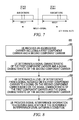
- FIG. 4 illustrates a process flow diagram
- FIG. 5 illustrates an exemplary coordination scheme for two component carriers.
- FIG. 6 is a schematic illustrating I/Q imbalance image compensation.
- FIG. 7 illustrates intra-band contiguous aggregated carrier.
- FIG. 8 illustrates another process flow diagram.
- a wireless communication system 100 comprises one or more fixed base infrastructure units 101 , 102 forming a network distributed over a geographical region for serving remote units in the time and/or frequency and/or spatial domain.
- a base unit may also be referred to as an access point, access terminal, base, base station, NodeB, enhanced NodeB (eNodeB), Home NodeB (HNB), Home eNodeB (HeNB), Macro eNodeB (MeNB), Donor eNodeB (DeNB), relay node (RN), femtocell, femto-node, network node or by other terminology used in the art.
- the one or more base units each comprise one or more transmitters for downlink transmissions and one or more receivers for uplink transmissions.
- the base units are generally part of a radio access network that includes one or more controllers communicably coupled to one or more corresponding base units.
- the access network is generally communicably coupled to one or more core networks, which may be coupled to other networks like the Internet and public switched telephone networks among others. These and other elements of access and core networks are not illustrated but are known generally by those having ordinary skill in the art.
- the one or more base units serve a number of remote units 103 , 104 within a corresponding serving area, for example, a cell or a cell sector, via a wireless communication link.
- the remote units may be fixed or mobile.
- the remote units may also be referred to as subscriber units, mobiles, mobile stations, mobile units, users, terminals, subscriber stations, user equipment (UE), user terminals, wireless communication devices, relay node, or by other terminology used in the art.
- the remote units also comprise one or more transmitters and one or more receivers.
- the base unit 101 transmits downlink communication signals to serve remote unit 103 in the time and/or frequency and/or spatial domain.
- the remote unit 104 communicates with base unit 102 via uplink communication signals. Sometimes the base unit is referred to as a serving or connected or anchor cell for the remote unit.
- the remote units may also communicate with the base unit via a relay node.
- the wireless communication system is compliant with the 3GPP Universal Mobile Telecommunications System (UMTS) LTE protocol, also referred to as EUTRA or 3GPP LTE or some later generation thereof, wherein the base unit transmits using an orthogonal frequency division multiplexing (OFDM) modulation scheme on the downlink and the user terminals transmit on the uplink using a single carrier frequency division multiple access (SC-FDMA) scheme.
- UMTS Universal Mobile Telecommunications System
- SC-FDMA single carrier frequency division multiple access
- the wireless communication system may implement some other open or proprietary communication protocol, for example, IEEE 802.16(d) (WiMAX), IEEE 802.16(e) (mobile WiMAX), among other existing and future protocols.
- the disclosure is not intended to be implemented in any particular wireless communication system architecture or protocol.
- the architecture may also include the use of spreading techniques such as multi-carrier CDMA (MC-CDMA), multi-carrier direct sequence CDMA (MC-DS-CDMA), Orthogonal Frequency and Code Division Multiplexing (OFCDM) with one or two dimensional spreading.
- MC-CDMA multi-carrier CDMA
- MC-DS-CDMA multi-carrier direct sequence CDMA
- OFDM Orthogonal Frequency and Code Division Multiplexing
- the architecture in which the features of the instant disclosure are implemented may also be based on simpler time and/or frequency division multiplexing/multiple access techniques, or a combination of these various techniques.
- the wireless communication system may utilize other communication system protocols including, but not limited to, TDMA or direct sequence CD
- E-UTRA systems also facilitate the use of multiple input and multiple output (MIMO) antenna systems on the downlink to increase capacity.
- MIMO antenna systems are employed at the eNB through use of multiple transmit antennas and at the UE through use of multiple receive antennas.
- a UE may rely on a pilot or reference symbol (RS) sent from the eNB for channel estimation, subsequent data demodulation, and link quality measurement for reporting.
- the link quality measurements for feedback may include such spatial parameters as rank indicator (RI), or the number of data streams sent on the same resources; precoding matrix index (PMI); and coding parameters, such as a modulation and coding scheme (MCS) or a channel quality indicator (CQI).
- MCS modulation and coding scheme
- CQI channel quality indicator
- MCS or CQI, PMI and RI constitute elements of the Channel State Information (CSI) which convey the quality of MIMO channel indicative of the reliability and condition number of the channel capable of supporting multi-stream communication between the eNB and the UE.
- CSI Channel State Information
- the link quality measurements may be reported on a periodic or aperiodic basis, as instructed by an eNB, in one of the supported feedback modes.
- the reports may include wideband or subband frequency selective information of the parameters.
- the eNB may use the rank information, the CQI, and other parameters, such as uplink quality information, to serve the UE on the uplink and downlink channels.
- Spatial multiplexing transmission can either be CRS-based (i.e., UE utilizes CRS for both CQI/PMI/RI estimation and for demodulation) or DRS-based (i.e., UE uses either CRS or CSI-RS for CQI/PMI/RI estimation and uses DRS for demodulation).
- an uplink data channel may be a Physical Uplink Shared Channel (PUSCH)
- an uplink control channel may be a physical uplink control channel (PUCCH)
- a downlink control channel may be a physical downlink control channel (PDCCH)
- downlink data channel may be a physical downlink shared channel (PDSCH).
- Uplink control information may be communicated over the PUCCH and/or the PUSCH and downlink control information is communicated typically over the PDCCH.
- the UE may further transmit uplink sounding reference signals to assist the eNB on scheduling uplink (for frequency division duplex (FDD)) and for one or both uplink and downlink for time-division duplex (TDD).
- FDD frequency division duplex
- TDD time-division duplex
- the base station transmits using an OFDM modulation scheme on the downlink and the UEs transmit on the uplink using a single carrier frequency division multiple access (SC-FDMA) scheme and/or Discrete Fourier Transform Spread OFDM (DFT-SOFDM).
- SC-FDMA single carrier frequency division multiple access
- DFT-SOFDM Discrete Fourier Transform Spread OFDM
- the UE may transmit using contiguous or non-contiguous resource allocations and the UE may also transmit data and control on the uplink simultaneously using the so-called simultaneous PUCCH and PUSCH transmission scheme.
- the frame structure in the uplink and downlink each comprises of a 10 millisecond (ms) Radio frame, which is in turn divided into ten subframes each of 1 ms duration wherein each subframe is divided into two slots of 0.5 ms each, wherein each slot contains a number of OFDM symbols.
- the downlink and uplink bandwidth are subdivided into resource blocks, wherein each resource block comprises of one or more subcarriers in frequency and one or more OFDM symbols in the time domain (12 subcarriers ⁇ 7 OFDM symbols for normal Cyclic Prefix (CP)).
- resource blocks are defined on a slot basis.
- a resource block (RB) is typical unit in which the resource allocations are assigned for the uplink and downlink communications.
- the eNB configures appropriate channels for uplink and downlink control information exchange.
- the physical downlink control channel (PDCCH) is used for sending the uplink and downlink control information to the UEs.
- the PDCCH is sent in the beginning portion of a subframe on a potentially variable number of OFDM symbols, and this number (typically 0 to 3 for large system bandwidths such as 5 MHz, etc and 0 to 4 for smaller system bandwidths such as 1.25 MHz) is signaled on the Physical Control Format Indicator Channel (PCFICH) or sent via higher layer signaling.
- PCFICH Physical Control Format Indicator Channel
- the PDCCH may also be located in certain fixed or variable time/frequency/spatial resources i.e., spanning one or more subcarriers in one or more subframes and/or one or more spatial layers. For example, it may occupy a subset of resource blocks instead of spanning the entire DL system bandwidth.
- the Physical Hybrid ARQ Channel (PHICH) is the Acknowledgment indicator channel used to send the HARQ feedback on the DL for the uplink data transmissions from the UE.
- the PCFICH, PHICH, PDCCH are sent on OFDM symbols at the beginning of the DL subframes. In some subframes such as ABS or when the eNB has no UEs scheduled (i.e.
- the master information block (MIB) is sent on the Physical Broadcast CHannel (PBCH), the MIB comprises of system frame number (SFN), downlink system bandwidth, number of signaled downlink transmit antennas (or the number of CRS ports), and Physical Hybrid ARQ Channel (PHICH) configuration (i.e. duration).
- the PBCH is sent on subframe 0 (each subframe comprising of two slots, each slot corresponding to a 0.5 milli-second).
- the Synchronization signals are transmitted on the inner six PRBs or inner 72 subcarriers (i.e. 1.25 MHz) on subframes 0 and 5. The exact location of the Synchronization signals depends upon the duplex type, Cyclic Prefix length, etc.
- the subframe may contain an initial portion (near the beginning of the subframe) containing a unicast region and the rest of the subframe may be configured differently based on the higher layer signaling. If the MBSFN subframe is used for transmission of multicast transmission channel (MTCH), then the rest of the subframe may contain multicast OFDM symbols with cyclic prefix (CP) that may be distinct (and likely larger) than the CP used for the initial transmission.
- MTCH multicast transmission channel
- CP cyclic prefix
- the MBSFN subframe configuration is typically sent in the System Information Block (SIB) SIB2 message, wherein the SIB2 message is a higher layer message sent on the PDSCH by the eNB.
- SIB System Information Block
- the schedule of SIB2, SIB3, (and other SIB messages) is indicated in SIM.
- the System information typically changes on the order of SIB transmission window (e.g. in multiples of 8 ms) i.e. the system information update only when a new SI-transmission window begins and the UEs are paged to indicate a SI update so that they can re-acquire system information.
- SIB transmissions are not allowed in MBSFN subframes as there may be no CRS in the data region of the MBSFN subframes.
- a User Equipment can receive and transmit control and data signaling on multiple component carriers (CCs). Initially, the UE may communicate with the network by receiving only a single CC (Primary or Anchor CC). In some implementations, the network sends a configuration message (SI configuration message) to the UE on the primary CC with system information (SI) corresponding to other CCs on which the network may schedule the UE.
- SI configuration message a configuration message
- SI configuration message to the UE on the primary CC with system information (SI) corresponding to other CCs on which the network may schedule the UE.
- SI typically includes CC specific information that the UE is required to store in order to communicate with the network on other CCs.
- the SI can include CC specific information such as CC carrier frequency, downlink (DL) bandwidth, number of antennas, downlink reference signal power, uplink (UL) power control parameters and other information that does not change frequently.
- base station sends the SI configuration message to the UE using Radio Resource Configuration (RRC) signaling, since the SI does not change frequently and the payload associated with the SI configuration is relatively large.
- RRC Radio Resource Configuration
- the UE Upon receipt of the SI configuration, the UE stores the SI for other CCs but continues to communicate with the network by only receiving the primary CC.
- the other CCs for which the UE has received SI and the primary CC constitute the UE's “configured CC set”.
- a wireless communication terminal receives an aggregated carrier including a first component carrier and a second component carrier, as indicated at 410 , from one or more base stations in the wireless communication system.
- the first component carrier generally comprises a reference signal (RS).
- the reference signal is embodied as a cell-specific reference signal (CRS), a positioning reference signal (PRS), UE reference signal (UE-RS), Channel State Information Reference Signal (CSI-RS), a Demodulation reference signal (DRS or DM-RS), a pilot signal, a beacon signal among other reference symbols or signals that may be used as a basis for determining a leakage from the first component carrier to the second component carrier as described more fully below.
- the UE measures leakage of the reference signal from the first component carrier onto the second component carrier.
- the reference signal is transmitted on a particular time slot, for example on the first component carrier in the example described above.
- the reference signal leakage from the first component carrier is measured on a corresponding time slot on the second component carrier.
- the time slots on the first and second component carriers are coincident in the time domain, although in some circumstances they may be only partially aligned or overlapping in the time domain.
- pilots transmitted on one CC can be used to estimate the component of the image on a second CC. This can be accomplished by coordinating transmission on the two CCs where transmit/blank time slots or zones are created.
- FIG. 5 illustrates an exemplary coordination scheme for two CCs, where the eNB blanks transmission on CC 2 when CC 1 transmits only pilots on one time slot and the eNB blanks CC 1 when CC 2 transmits only pilots in a second time slot.
- a blank slot can be created by configuring a MBSFN subframe and not scheduling PDSCH in that subframe (and as a result CRS is also absent in such a subframe) such that the blank slot is equivalent to the entire non-control region.
- a transmit slot can be created by configuring a normal subframe that does not carry any PDSCH (but, by definition carries at least the CRS).
- CRS from only one antenna port may be transmitted to assist image compensation.
- Image compensation can be summarily described as follows.
- Receiving a RS transmission on the first CC results in a leakage component on the second CC due to receiver non-linearity.
- the leakage component is a function of both the received RS (with known signal structure) and some variables that parameterize the receiver non-linearity (in this case, IQ gain and phase imbalance which is also known as the quadrature non-linearity).
- the received signal on the second CC and the known RS sequence are made use of to estimate the variables that parameterize the receiver non-linearity.
- a compensation circuit can make use of these parameters to pre-compensate the signal received on the second CC before the signal is processed to extract data embedded in the signal.
- the compensation circuit can estimate the leakage signal component that is corrupting the portion of the signal corresponding to the second CC on a real-time basis and subtract it off prior to FFT processing as shown in FIG. 6 .
- the positioning reference signal PRS
- the leakage of the reference signal from the first component carrier onto the second component carrier is measured only intermittently, for example, during a time interval that may be considered a training period. The measurement or estimation of the leakage may also be made periodically, for example, every few milliseconds or every second or so.
- the UE receives scheduling information from the base station indicating when the reference signal will be transmitted on the first component carrier.
- the scheduling information is indicative of a time offset and in some embodiments a periodicity for the reference signal.
- the time offset may be indicative of when the reference signal will be received relative to some reference, e.g., the beginning of a frame or subframe, and the periodicity may indicate how frequently the reference signal is transmitted.
- the UE need not measure leakage on every transmission of the reference signal.
- the frequency with which the leakage is measured may be predicated on some criteria, for example, a metric indicative of motion or velocity of the UE or some other metric indicative of a need for updating the leakage measurement.
- the UE receives a signal on the aggregated carrier, for example, on the first and second component carriers described above.
- the UE compensates for leakage of the signal from the first component carrier to the second component carrier based on the measurement of the leakage of the reference signal.
- the UE generates or estimates one or more parameters based on the measurement of the leakage of the reference signal. In the example, above this leakage occurs from the first component carrier to the second component carrier.
- the UE compensates for the leakage by applying a transformation of the parameter to the received signal.
- the transformation may be in the time domain or in the frequency domain.
- the transformation of the parameter to the received signal is a linear combination of the received signal scaled by a first coefficient and a complex conjugate of the received signal scaled by a second coefficient, and wherein the first and second coefficients of the linear combination are a function of the estimated parameter.
- FIGS. 6 illustrates an implementation where the parameters associated with the image of CC 1 are estimated (post-FFT and based on a signal template of pilot transmission in CC 1 ) and are used for compensating for the CC 1 's image in time-domain (prior to FFT) in CC 2 's receive chain. This is applicable to both single-FFT and multiple-FFT architectures illustrated in FIGS. 1 and 2 .
- the carrier separation for intra-band CA is multiple of 300 kHz (i.e., the least common multiple of raster spacing 100 kHz and subcarrier spacing 15 kHz). This allows the use of a single FFT receiver for demodulating multiple aggregated CCs within the same band.
- the simplest case of 10 MHz+10 MHz intra-band contiguous CA is shown in FIG. 7 .
- x 1 (t) and x 2 (t) represent the time-domain signals for CC# 1 and CC# 2 respectively.
- N is the number of subcarriers in each CC.
- the second CC leaks into the first and vice-versa.
- the image is proportional to the complex-conjugate of the signal reversed in sequence in the frequency-domain and shifted by one subcarrier. If uncompensated, this image term can limit the achievable SNR in each CC.
- both CRS can be transmitted on both CCs in CRS-only subframes (e.g., almost blank subframe configured on a normal subframe where PDSCH is not transmitted). Muting transmission on all CRS ports except for one (e.g., port #0) can further reduce the likelihood of CRS collision.
- a FFT of size 2N FFT can be used for extracting signals for the two CCs in the present embodiment.
- the signal after the ADC stage is bandpass filtered prior to FFT to extract a signal corresponding to the two CCs in an alternate embodiment.
- a unified approach can be developed for estimating ⁇ and ⁇ for both the single and dual FFT receivers (i.e., both embodiments) as the response of bandpass filter in the multiple FFT case is known for each implementation.
- Estimating the parameters ⁇ and ⁇ based on CRS transmission in one or both CCs can constitute the first step in IQ imbalance compensation. After estimating these parameters, a correction can be carried out in time domain (pre-FFT) for both single-FFT and dual-FFT implementations as shown in FIG. 6 by making use of the equation:
- z corr ⁇ ( t ) ⁇ _ ⁇ ⁇ z ⁇ ( t ) - ⁇ ⁇ ⁇ z _ ⁇ ( t ) ⁇ ⁇ ⁇ 2 - ⁇ ⁇ ⁇ 2 ⁇ ,
- z(t) is the time-domain signal for a single CC (dual-FFT receiver) or all CCs (single-FFT receiver).
- the index l maps to index k in set S Z in a one-to-one fashion.
- H (j) (l) is the actual channel response on CC#j (i.e., noise-less channel response or ideal channel estimate)
- ⁇ l 's are the (known) filter response coefficients for receiving a signal on CC# 2 in the BW of CC# 1 and ⁇ l is the corresponding filter response for receiving signal on CC# 1 in the BW of CC# 2 .
- these coefficients are known implementation-dependent constants.
- h(n) are the time-domain channel response coefficients and W L ⁇ P (j) is the subsampled matrix of a 2N FFT ⁇ 2N FFT DFT matrix applicable to the reception of CRS subcarriers in CC#j, and P is the length of the channel response at sample rate 2N FFT .
- the parameters ( ⁇ , ⁇ ) and the channel response h can be jointly estimated by the minimization problem:
- FIG. 6 illustrates an implementation where parameters associated with the image of CC 1 are estimated (post-FFT and based on signal template of pilot transmission in CC 1 ) and are used for compensating for the CC 1 's image in time-domain (prior to FFT) in CC 2 's receive chain. This is applicable to both single-FFT and multiple-FFT architectures.
- the time-domain compensation for IQ imbalance as shown in Appendix A can be applied on a per-receive antenna basis. This method is therefore applicable to multi-layer transmissions.
- the UE generally comprises a controller coupled to a wireless transceiver wherein the controller is configured to cause the UE to perform the various functions described herein including receiving the aggregated carrier, measuring leakage of the reference signal, receiving a signal on the aggregated carrier, and compensating for the leaking among the other functionality described herein.
- the methods and functions described herein may be performed by a digital processor executing software of firmware residing in a memory device. Alternatively the functionality of the UE may be performed by equivalent hardware or by a combination of hardware and software.
- the eNB also comprises a controller coupled to a wireless transceiver wherein the controller is configured to cause the eNB to perform the various functions described herein including transmitting scheduling information indicating when the reference signal will be transmitted, transmitting the reference signal on at least one of the indicated time slots, and blanking a data signal transmission on a second component carrier on a time slot that at least partially overlaps in time with the time slot where the reference signal is transmitted on the first component carrier among other functionality provided herein.
- the functionality of the eNB may be performed by equivalent hardware or by a combination of hardware and software.
- the wireless communication terminal receives an aggregated carrier including a first component carrier and a second component carrier, as indicated at 810 , from one or more base stations in the wireless communication system.
- the UE determines a signal characteristic of the first component carrier and a signal characteristic of the second component carrier.
- the signal characteristic of the component carriers is selected from a group comprising a reference signal received power (RSRP), a reference signal strength indicator (RSSI), a total received power, a channel quality indicator (CQI), and a hypothetical block error rate (BLER) applicable to a packet-coded transmission.
- RSRP reference signal received power
- RSSI reference signal strength indicator
- CQI channel quality indicator
- BLER hypothetical block error rate
- the UE determines a level of interference from a signal received on the first component carrier to a signal on the second component carrier based on the signal characteristic of the first component carrier and the signal characteristic of the second component carrier.
- the determines a reference signal received power (RSRP) of the first component carrier and a reference signal received power (RSRP) of the second component carrier.
- the level of interference may then be determined based on a ratio of the RSRP of the first component carrier with respect to the RSRP of the second component carrier.
- the level of interference may be determined by comparison of a difference of a logarithm of the RSRP of the first and second carrier components and comparison of the difference to a threshold.
- the UE provides signal interference information to a serving base station if the determined interference level satisfies a condition. Satisfaction of the conditions may be determined by comparison of the ratio to a threshold. In one embodiment, the UE indicates the signal interference information to the base station only when both the determined interference level satisfies the condition and upon determining that a modulation coding scheme scheduled on the second component carrier is subject to a specified level of interference from the first component carrier, as described more fully below. In some instances, the UE receives a primary serving cell change command from the serving base station in response to sending the signal interference information to the serving base station.
- the UE generally comprises a controller coupled to a wireless transceiver wherein the controller is configured to cause the UE to perform the various functions described herein including receiving the aggregated carrier, measuring leakage of the reference signal, determining signal characteristics on the component carriers, determining the level of interference, and providing signal interference information to the base station among the other functionality described herein.
- the methods and functions may be performed by a digital processor executing software of firmware residing in a memory device. Alternatively the functionality of the UE may be performed by equivalent hardware or by a combination of hardware and software.
- the eNB also comprises a controller coupled to a wireless transceiver wherein the controller is configured to cause the eNB to perform the various functions described herein including receiving and processing messages from the UE indicating that an impairment from a signal transmitted on a first component carrier to a signal transmitted on the second component carrier exceeds a certain level, configuring a third component carrier as a new primary cell component carrier, and sending a user-specific message to the wireless terminal indicating that the third component carrier has been configured as the new primary cell component carrier, among other functionality provided herein.
- the functionality of the eNB may be performed by equivalent hardware or by a combination of hardware and software.
- the second component carrier is configured as a primary serving cell and the first component carrier is configured as a secondary serving cell.
- the UE configures a third component carrier as a new primary serving cell.
- the first component carrier is configured as the primary serving cell and the second component carrier is configured as the secondary serving cell.
- the third component carrier corresponds to the first component carrier.
- the UE receives a DCI grant indicating transmission of a sequence of information symbols according to a modulation order, a coding scheme on the second component carrier and a transmission mode such one of a single-layer transmission, a spatial multiplexing method, a transmit diversity method.
- a spatial multiplexing transmission scheme if spatial multiplexing transmission scheme is used, the transmission can be based either on CRS or on DRS (and the transmission rank associated with the transmission can be equal to one of 1, 2, 3, 4 for CRS-based transmission and equal to one of 1, 2, . . . , 8 for DRS-based transmission).
- the UE also determines a level of interference that the sequence of information symbols is subject to from the first component carrier based on the signal characteristic of the first component carrier and the signal characteristic of the second component carrier. The UE then indicates the signal interference information to the base station only if the level of interference satisfies a condition as described above.
- the UE sends an indication to the eNB identifying that there is a problem only when the condition is met (i.e., when Scell RSRP minus Pcell RSRP>10 dB), and when the UE receives a DCI grant indicating that a MCS belonging to a certain range (MCS 16 - 28 in this example) is likely to have degraded performance has been scheduled.
- the degradation of PDSCH w.r.t. BLER can also be function of the transmission scheme used. For example, the BLER degradation can be more severe for higher rank transmission. Therefore, in an alternate embodiment, the UE can send an indication only when both an MCS within a pre-determined range is scheduled and when the spatial multiplexing transmission rank exceeds a pre-determined value.
- the eNB can schedule a lower MCS or a transmission with lower rank if the effective throughput is increased by lowering the MCS or the transmission rank. It is possible that the packet reception loss associated with the current MCS/rank is small and lowering the MCS can reduce the effective throughput, in which case, the eNB does not lower the MCS or transmission rank.
- UE-measured CQI can track SINR degradation due to I/Q imbalance in constant loading or slowly-varying conditions. But, there are some scenarios where this may not be possible particularly when the loading on the Scell is bursty.
- the eNB scheduler may take into account the NACK running average (i.e., UE actual decoding error rate) in addition to the reported to CQI in its scheduling decisions. But, as described previously in one of the embodiments, the RSRP difference between the Pcell and Scell can be used to detect a potential leakage problem as RSRP remains invariant to the loading conditions on the Scell. This can then be used to alert the eNB against possible over-scheduling of MCS.
- the UE can detect that its Pcell is being desensed by the Scell image when the RSRP difference between the Pcell and Scell is large.
- the UE's image rejection capability which is a receiver-specific implementation property, can be calibrated. Since the UE monitors Pcell RSRP and Scell RSRP on a continuous basis (both when in DRX and in non-DRX), it can determine whether RSRP( S cell) ⁇ RSRP( P cell)>threshold — A.
- the UE can determine whether RSSI( S cell) ⁇ RSRP( P cell)>threshold — B OR RSSI( S cell) ⁇ RSSI( P cell)>threshold — C.
- the UE can send an indication to the serving eNB (say, over Pcell UL) that Pcell downlink (DL) is likely to get desensed by the Scell image.
- the quantity threshold_A can be a pre-calibrated threshold determined, for example, based on receiver gain/phase imbalance by the UE manufacturer.
- the eNB can use this report as a trigger to re-configure the UE's Pcell. For example, the strongest Scell can be configured as a new Pcell for the UE.
- the UE can also report a Scell index or identifier to indicate which Scell is or may be desensing the Pcell. As a further restriction to reporting, the UE can send such a report only when a MCS with sufficiently high modulation order/code rate combination that is likely to be impacted by the desense problem is being scheduled, otherwise the UE need not send a report.
- the UE sends a request to the eNB asking that a certain Scell be configured as the new Pcell.
- the UE can determine (e.g., based on RSSI measurements on the Scell) that the Scell is heavily loaded, in which case the UE can request the eNB to perform an inter-frequency handover to a new Pcell.
- the UE can request the eNB that the Scell be activated (if it is currently deactivated) and the UE can be scheduled only on a Scell, wherein scheduling is performed either by PDCCH on the Scell or by means of inter-CC scheduling where PDCCH is sent on the Pcell.
- the UE can also advertise its image rejection capability. For example, the UE can send Adjacent Channel Interference Rejection Ratio (ACIRR) on its uplink (UL) to the eNB. This will enable the eNB to determine if there is an image problem based on RSRP reports that the UE sends on a periodic basis.
- ACIRR Adjacent Channel Interference Rejection Ratio
- a wireless communication terminal receives a request from a serving base station for wireless communication terminal capability information.
- the UE sends capability information to the serving base station, wherein the capability information includes an Adjacent Channel Interference Rejection Ratio (ACIRR) for at least one carrier frequency (e.g., EARFCN) pair as part of the RRC capability information exchange.
- ACIRR Adjacent Channel Interference Rejection Ratio
- the UE sends ACIRR together with either a band combination or a carrier aggregation bandwidth class.
- the UE sends separate ACIRR values for each band combination, each carrier aggregation bandwidth class, etc.
- the UE can send the ACIRR values at different frequencies possibly in relation the different serving cell component carrier frequencies (e.g., If Pcell at carrier frequency F 1 , ACIRR corresponding to Scell # 1 at carrier frequency F 2 , Scell # 2 at carrier frequency F 3 , etc. are sent by the UE to the eNB).
- receiver impairments due to LO IQ gain/phase imbalance can be readily extended to the compensation of other receiver impairments such as phase noise and carrier frequency offset.
- the effect of receiver impairments on the received signal in many cases, can be parameterized by a few variables which can be estimated by suitable processing of the received RS sequence.
- a compensation circuit that makes use of the estimated parameters can be designed to mitigate the effect of the receiver impairment in the received signal.
Landscapes
- Engineering & Computer Science (AREA)
- Signal Processing (AREA)
- Computer Networks & Wireless Communication (AREA)
- Mobile Radio Communication Systems (AREA)
Priority Applications (7)
| Application Number | Priority Date | Filing Date | Title |
|---|---|---|---|
| US13/031,383 US8619716B2 (en) | 2011-02-21 | 2011-02-21 | IQ imbalance image compensation in multi-carrier wireless communication systems |
| PCT/US2012/024626 WO2012115800A1 (fr) | 2011-02-21 | 2012-02-10 | Rapport de perte de signal entre des composantes porteuses due à un déséquilibre iq dans des systèmes de communication sans fil à porteuses multiples |
| EP15157040.5A EP2908490A1 (fr) | 2011-02-21 | 2012-02-10 | Compensation de fuites entre des porteuses de composantes dues à un déséquilibre iq dans des systèmes de communication sans fils à porteuses multiples |
| EP12705562.2A EP2678987B1 (fr) | 2011-02-21 | 2012-02-10 | Rapport de perte de signal entre des composantes porteuses due à un déséquilibre IQ dans des systèmes de communication sans fil à porteuses multiples |
| ES12705562.2T ES2535828T3 (es) | 2011-02-21 | 2012-02-10 | Reporte de fugas entre portadoras componentes debido a desequilibrio IQ en sistemas de comunicación inalámbricos de múltiples portadoras |
| US13/953,768 US9491641B2 (en) | 2011-02-21 | 2013-07-30 | IQ imbalance image compensation in multi-carrier wireless communication systems |
| US13/953,770 US9794802B2 (en) | 2011-02-21 | 2013-07-30 | IQ imbalance image compensation in multi-carrier wireless communication systems |
Applications Claiming Priority (1)
| Application Number | Priority Date | Filing Date | Title |
|---|---|---|---|
| US13/031,383 US8619716B2 (en) | 2011-02-21 | 2011-02-21 | IQ imbalance image compensation in multi-carrier wireless communication systems |
Related Child Applications (2)
| Application Number | Title | Priority Date | Filing Date |
|---|---|---|---|
| US13/953,768 Continuation US9491641B2 (en) | 2011-02-21 | 2013-07-30 | IQ imbalance image compensation in multi-carrier wireless communication systems |
| US13/953,770 Continuation US9794802B2 (en) | 2011-02-21 | 2013-07-30 | IQ imbalance image compensation in multi-carrier wireless communication systems |
Publications (2)
| Publication Number | Publication Date |
|---|---|
| US20120213095A1 US20120213095A1 (en) | 2012-08-23 |
| US8619716B2 true US8619716B2 (en) | 2013-12-31 |
Family
ID=45755542
Family Applications (3)
| Application Number | Title | Priority Date | Filing Date |
|---|---|---|---|
| US13/031,383 Active 2031-12-18 US8619716B2 (en) | 2011-02-21 | 2011-02-21 | IQ imbalance image compensation in multi-carrier wireless communication systems |
| US13/953,770 Active 2031-11-08 US9794802B2 (en) | 2011-02-21 | 2013-07-30 | IQ imbalance image compensation in multi-carrier wireless communication systems |
| US13/953,768 Active US9491641B2 (en) | 2011-02-21 | 2013-07-30 | IQ imbalance image compensation in multi-carrier wireless communication systems |
Family Applications After (2)
| Application Number | Title | Priority Date | Filing Date |
|---|---|---|---|
| US13/953,770 Active 2031-11-08 US9794802B2 (en) | 2011-02-21 | 2013-07-30 | IQ imbalance image compensation in multi-carrier wireless communication systems |
| US13/953,768 Active US9491641B2 (en) | 2011-02-21 | 2013-07-30 | IQ imbalance image compensation in multi-carrier wireless communication systems |
Country Status (4)
| Country | Link |
|---|---|
| US (3) | US8619716B2 (fr) |
| EP (2) | EP2908490A1 (fr) |
| ES (1) | ES2535828T3 (fr) |
| WO (1) | WO2012115800A1 (fr) |
Cited By (2)
| Publication number | Priority date | Publication date | Assignee | Title |
|---|---|---|---|---|
| US9603180B2 (en) | 2015-02-18 | 2017-03-21 | Qualcomm Incorporated | Managing tune-away in a multi-subscriber identity module communication device |
| US20170105219A1 (en) * | 2012-09-28 | 2017-04-13 | Nokia Solutions And Networks Oy | Reporting Information |
Families Citing this family (48)
| Publication number | Priority date | Publication date | Assignee | Title |
|---|---|---|---|---|
| US20120214540A1 (en) | 2011-02-21 | 2012-08-23 | Motorola Mobility, Inc. | Signal Measurement on Component Carriers in Wireless Communication Systems |
| US8619716B2 (en) | 2011-02-21 | 2013-12-31 | Motorola Mobility Llc | IQ imbalance image compensation in multi-carrier wireless communication systems |
| US9729260B2 (en) * | 2011-02-24 | 2017-08-08 | Telefonaktiebolaget Lm Ericsson (Publ) | Reducing interference caused by an atmospheric duct in a mobile communication system |
| KR20120111834A (ko) * | 2011-04-02 | 2012-10-11 | 주식회사 팬택 | 무선통신시스템에서 이종셀간 간섭조정을 위한 제어정보의 전송장치 및 방법 |
| US20140192663A1 (en) * | 2011-04-06 | 2014-07-10 | Claudio Rosa | Power Difference Between SCell and PCell in a Carrier Aggregation System |
| EP2564611B1 (fr) | 2011-07-01 | 2015-02-18 | Ofinno Technologies, LLC | Signal de synchronisation et messages de commande en ofdm à porteuse multiple |
| US8582527B2 (en) * | 2011-07-01 | 2013-11-12 | Ofinno Technologies, Llc | Hybrid automatic repeat request in multicarrier systems |
| US8369280B2 (en) | 2011-07-01 | 2013-02-05 | Ofinno Techologies, LLC | Control channels in multicarrier OFDM transmission |
| CN102984746A (zh) * | 2011-09-05 | 2013-03-20 | 爱立信(中国)通信有限公司 | 提高网络中性能的参考信号功率测量和报告 |
| US9402264B2 (en) * | 2011-09-30 | 2016-07-26 | Intel Corporation | Methods to transport internet traffic over multiple wireless networks simultaneously |
| EP2579487B1 (fr) * | 2011-10-03 | 2014-05-21 | ST-Ericsson SA | Agrégation de porteuses non contigues |
| US8842637B2 (en) | 2011-12-04 | 2014-09-23 | Ofinno Technologies, Llc | Carrier information transmission to wireless devices |
| CN102448174B (zh) * | 2012-01-09 | 2015-08-12 | 中兴通讯股份有限公司 | 一种无线资源控制方法和装置 |
| US9497756B2 (en) | 2012-03-25 | 2016-11-15 | Comcast Cable Communications, Llc | Base station radio resource management |
| US9949265B2 (en) | 2012-05-04 | 2018-04-17 | Comcast Cable Communications, Llc | Control channel in a wireless communication system |
| US9584297B2 (en) * | 2012-05-11 | 2017-02-28 | Qualcomm Incorporated | Interference management for adaptive TDD with frequency domain separations |
| KR102021590B1 (ko) * | 2012-06-04 | 2019-09-18 | 삼성전자주식회사 | 무선 통신 시스템에서 제어 정보 송수신 방법 및 장치 |
| KR101972945B1 (ko) | 2012-09-18 | 2019-04-29 | 삼성전자 주식회사 | 무선 통신 시스템에서 채널 상태 정보 송수신 방법 및 장치 |
| CN109246822A (zh) | 2012-09-24 | 2019-01-18 | 华为技术有限公司 | 传输广播消息的方法、基站和用户设备 |
| US9596065B2 (en) | 2012-10-24 | 2017-03-14 | Qualcomm Incorporated | Enhanced SRS transmission for MIMO operation in LTE-A |
| US9407302B2 (en) * | 2012-12-03 | 2016-08-02 | Intel Corporation | Communication device, mobile terminal, method for requesting information and method for providing information |
| CN104871507B (zh) | 2012-12-21 | 2019-06-14 | 三星电子株式会社 | 用于在通信系统中发送/接收信号的方法和装置 |
| CN104823422B (zh) * | 2013-05-30 | 2018-03-23 | Lg 电子株式会社 | 解码下行链路数据的方法和装置 |
| US9692700B1 (en) | 2013-08-28 | 2017-06-27 | Juniper Networks, Inc. | Processing data flows based on information provided via beacons |
| DE102013113457B4 (de) * | 2013-12-04 | 2017-07-06 | Intel IP Corporation | Verfahren und vorrichtung zum erkennen eines interferenzszenarios |
| US9706923B2 (en) * | 2014-02-25 | 2017-07-18 | General Electric Company | System and method for adaptive interference mitigation in wireless sensor network |
| US9716573B2 (en) | 2014-06-13 | 2017-07-25 | Futurewei Technologies, Inc. | Aggregated touchless wireless fronthaul |
| WO2016019494A1 (fr) * | 2014-08-04 | 2016-02-11 | 华为技术有限公司 | Procédé et dispositif de création de rapport de qualité de canal |
| WO2016074185A1 (fr) * | 2014-11-13 | 2016-05-19 | Qualcomm Incorporated | Transmission adaptative à détection de porteuse (csat) autonome dans le spectre non soumis à licence |
| US9473286B1 (en) * | 2014-12-01 | 2016-10-18 | Sprint Spectrum L.P. | Management of carrier-aggregation based on predicted intermodulation distortion |
| US10652003B2 (en) * | 2015-01-22 | 2020-05-12 | Texas Instruments Incorporated | HARQ design for high performance wireless backhaul |
| US9860051B2 (en) * | 2015-01-26 | 2018-01-02 | Nokia Solutions And Networks Oy | Method and apparatus for management of frequency-division-duplex and time-division-duplex carrier aggregation |
| TWI555360B (zh) * | 2015-03-27 | 2016-10-21 | In the uplink transmission system to solve the radio frequency is not perfect joint estimation compensation method | |
| US9755779B2 (en) * | 2015-04-17 | 2017-09-05 | Futurewei Technologies, Inc. | Digital representations of analog signals and control words using different multi-level modulation formats |
| US10027413B2 (en) | 2015-06-18 | 2018-07-17 | Futurewei Technologies, Inc. | Cascaded waveform modulation with an embedded control signal for high-performance mobile fronthaul |
| US20190014522A1 (en) * | 2015-08-21 | 2019-01-10 | Sharp Kabushiki Kaisha | Terminal device, base station device, communication control method, and program |
| US11290993B2 (en) * | 2015-11-01 | 2022-03-29 | Lg Electronics Inc. | Method for transmitting control information for MUST transmission in wireless communication system and device therefor |
| US10085206B2 (en) * | 2016-03-08 | 2018-09-25 | Wipro Limited | Methods and systems for optimization of cell selection in TD-SCDMA networks |
| CN106301398B (zh) * | 2016-07-29 | 2017-09-15 | 广东欧珀移动通信有限公司 | 降低谐波干扰的方法、天线装置及移动终端 |
| US10148311B2 (en) * | 2016-09-26 | 2018-12-04 | Lg Electronics Inc. | Studies about MSD level in aggregating a plurality of downlink carriers and two uplink carriers |
| US10727994B2 (en) * | 2017-01-09 | 2020-07-28 | Qualcomm Incorporated | Using sequences of pilot repetitions for receiver adaptation |
| EP4138334A1 (fr) * | 2017-03-24 | 2023-02-22 | Apple Inc. | Conception de mise en sourdine de signal de référence spécifique à une cellule (crs) pour une communication de type machine encore améliorée (efemtc) |
| JP2020515128A (ja) * | 2017-03-24 | 2020-05-21 | テレフオンアクチーボラゲット エルエム エリクソン(パブル) | チャネルラスタおよびナンバリング |
| US10420161B1 (en) | 2018-03-20 | 2019-09-17 | Sprint Spectrum L.P. | Controlling RF communication in a dual-connectivity scenario |
| US11349631B2 (en) * | 2018-03-26 | 2022-05-31 | Qualcomm Incorporated | Techniques for providing full-duplex communications in wireless radio access technologies |
| EP3588102B1 (fr) * | 2018-06-29 | 2022-01-05 | VIAVI Solutions, Inc. | Instruments d'essai et procédés de compensation de déséquilibre iq |
| WO2020150871A1 (fr) * | 2019-01-21 | 2020-07-30 | Nokia Shanghai Bell Co., Ltd. | Configuration de réception discontinue de dispositif terminal |
| US10873958B1 (en) | 2019-05-10 | 2020-12-22 | Sprint Spectrum L.P. | Controlling PRB allocation for dual-connectivity service |
Citations (38)
| Publication number | Priority date | Publication date | Assignee | Title |
|---|---|---|---|---|
| US20030185286A1 (en) | 1996-04-29 | 2003-10-02 | Elmer Yuen | Matched filter-based handoff method and apparatus |
| US20050047536A1 (en) | 2003-09-02 | 2005-03-03 | Kuo-Ming Wu | Method and apparatus for I/Q mismatch calibration in a receiver |
| US7020226B1 (en) | 2002-04-04 | 2006-03-28 | Nortel Networks Limited | I/Q distortion compensation for the reception of OFDM signals |
| US20060128339A1 (en) | 2000-05-18 | 2006-06-15 | Broadband Innovations, Inc. | Varactor tunable RF filters having low distortion and high signal level capability |
| US7158503B1 (en) | 1999-07-09 | 2007-01-02 | Nokia Corporation | Placement of idle periods |
| US7167513B2 (en) | 2001-12-31 | 2007-01-23 | Intel Corporation | IQ imbalance correction |
| US20080279221A1 (en) | 2007-05-07 | 2008-11-13 | Industrial Technology Research Institute | Method for estimating and compensating IQ imbalance in OFDM systems |
| US7466768B2 (en) | 2004-06-14 | 2008-12-16 | Via Technologies, Inc. | IQ imbalance compensation |
| US7599664B2 (en) | 1999-12-09 | 2009-10-06 | Nokia Corporation | Mobile equipment based filtering for packet radio service (PRS) |
| US7653164B2 (en) | 2001-12-31 | 2010-01-26 | Intel Corporation | Adaptive IQ imbalance correction for multicarrier wireless communication systems |
| US20100120442A1 (en) | 2008-11-12 | 2010-05-13 | Motorola, Inc. | Resource sharing in relay operations within wireless communication systems |
| US7742539B2 (en) | 2004-05-19 | 2010-06-22 | Telefonaktiebolaget L M Ericsson (Publ) | Adaptation of IQ-error compensation |
| US20100166049A1 (en) | 2008-12-30 | 2010-07-01 | Nxp B.V. | Receiver i-q balance calibration |
| US20100232395A1 (en) | 2007-08-08 | 2010-09-16 | Cambridge Silicon Radio Limited | FFT/IFFT Clock Adjustment |
| WO2010104365A2 (fr) | 2009-03-13 | 2010-09-16 | 엘지전자 주식회사 | Transfert effectué en considération d'une configuration de porteuse composante de liaison montante/liaison descendante |
| US7822399B2 (en) | 2007-05-11 | 2010-10-26 | Telefonaktiebolaget Lm Ericsson (Publ) | Image compensation for wireless receiver |
| US7831220B2 (en) | 2005-07-26 | 2010-11-09 | Broadcom Corporation | Methods and systems for calibrating for gain and phase imbalance and local oscillator feed-through |
| US7856065B2 (en) | 2007-05-02 | 2010-12-21 | Telefonkaktiebolaget Lm Ericsson (publ) | Method and apparatus for correcting IQ imbalance in an OFDM receiver |
| US20110021154A1 (en) | 2009-03-12 | 2011-01-27 | Interdigital Patent Holdings, Inc. | Method and apparatus for monitoring for a radio link failure |
| US20110026476A1 (en) | 2009-08-03 | 2011-02-03 | Lg Electronics Inc. | Apparatus And Method For Configuring Radio Connection In Multiple Component Carrier System |
| US20110032908A1 (en) * | 2008-01-22 | 2011-02-10 | Telefonaktiebolaget L M Ericsson | Method, computer program, receiver, and apparatus for determining a channel quality index |
| US20110081936A1 (en) | 2009-10-02 | 2011-04-07 | Interdigital Patent Holdings, Inc. | Method and apparatus for controlling transmit power of transmissions on more than one component carrier |
| US20110103333A1 (en) | 2008-06-19 | 2011-05-05 | Berggren Fredrik | Carrier aggregation |
| US20110212693A1 (en) | 2010-01-11 | 2011-09-01 | Telefonaktiebolaget L M Ericsson (Publ) | Measurement Handling with Carrier Aggregation |
| US20110255484A1 (en) | 2009-10-14 | 2011-10-20 | Qualcomm Incorporated | Downlink association set for uplink ack/nack in time division duplex system |
| US8050343B2 (en) | 2008-04-14 | 2011-11-01 | Telefonaktiebolaget Lm Ericsson (Publ) | Wireless communication methods and receivers for receiving and processing multiple component carrier signals |
| US20110267955A1 (en) | 2010-05-03 | 2011-11-03 | Nokia Corporation | Monitoring pattern separation between component carriers based on user equipment RF layout |
| US20110310830A1 (en) | 2010-06-18 | 2011-12-22 | Mediatek Inc. | Method for Coordinating Transmissions Between Different Communications Apparatuses and Communication Sapparatuses Utilizing the Same |
| US20110312328A1 (en) * | 2010-06-18 | 2011-12-22 | Infineon Technologies Ag | Communication terminal, communication device, method for data communication, and method for frequency allocation |
| US20110310753A1 (en) * | 2010-06-17 | 2011-12-22 | Mediatek Inc. | Measurement configuration in multi-carrier OFDMA wireless communication systems |
| US20120008563A1 (en) | 2009-03-17 | 2012-01-12 | Telefonaktiebolaget Lm Ericsson (Publ) | Power Backoff for Multi-Carrier Uplink Transmissions |
| US20120057449A1 (en) | 2009-05-29 | 2012-03-08 | Panasonic Corporation | Wireless communication apparatus and frequency hopping method |
| US20120113935A1 (en) | 2009-06-17 | 2012-05-10 | Telefonaktiebolaget L M Ericsson (Publ) | Scheduling Data Transmissions Between a Mobile Terminal and a Base Station in a Wireless Communications Network |
| US20120122472A1 (en) | 2010-11-12 | 2012-05-17 | Motorola Mobility, Inc. | Positioning Reference Signal Assistance Data Signaling for Enhanced Interference Coordination in a Wireless Communication Network |
| US20120275330A1 (en) | 2009-12-10 | 2012-11-01 | Nokia Corporation | Apparatus and method for cubic metric computation in dual-carrier and multi-carrier wireless communication system |
| US20120287875A1 (en) | 2010-03-17 | 2012-11-15 | Kim Kijun | Method and apparatus for providing channel state information-reference signal (csi-rs) configuration information in a wireless communication system supporting multiple antennas |
| US20120314675A1 (en) * | 2010-02-21 | 2012-12-13 | Lg Electronics Inc. | Method for managing carrier aggregation sets, and related devices |
| US20130036147A1 (en) | 2011-08-02 | 2013-02-07 | Mediatek Inc. | Infinite impulse response (iir) filter and filtering method |
Family Cites Families (19)
| Publication number | Priority date | Publication date | Assignee | Title |
|---|---|---|---|---|
| WO2003037027A1 (fr) | 2001-10-18 | 2003-05-01 | Fujitsu Limited | Systeme de communication mobile et procede de communication avec ledit systeme |
| JP5012581B2 (ja) * | 2008-03-06 | 2012-08-29 | 富士通株式会社 | 歪補償増幅装置および補正方法 |
| US8213537B2 (en) | 2009-01-23 | 2012-07-03 | Verizon Patent And Licensing Inc. | Apparatuses, systems, and methods for reducing spurious emissions resulting from carrier leakage |
| EP3793258B1 (fr) | 2009-03-16 | 2022-07-06 | Sun Patent Trust | Système de communication sans fil, appareil de terminal, appareil de station de base et procédé de communication sans fil |
| CN102396269B (zh) | 2009-04-14 | 2016-02-03 | 交互数字专利控股公司 | 用于解决向封闭用户组提供入站移动性的pci混乱的方法和装置 |
| WO2010126105A1 (fr) | 2009-04-28 | 2010-11-04 | 株式会社エヌ・ティ・ティ・ドコモ | Système de communication mobile, station de base sans fil, et procédé de commande associé |
| EP2436202B1 (fr) * | 2009-05-29 | 2019-08-07 | Nokia Solutions and Networks Oy | Réseau et procédé de communications |
| KR101237666B1 (ko) * | 2009-07-28 | 2013-02-26 | 엘지전자 주식회사 | 다중 입출력 통신 시스템에서 셀간 간섭을 제거하기 위한 기준신호 전송 방법 및 장치 |
| WO2011015223A1 (fr) * | 2009-08-03 | 2011-02-10 | Nokia Siemens Networks Oy | Réduction des interférences provenant de stations de base voisines dominantes en interférence |
| US8738065B2 (en) | 2009-10-02 | 2014-05-27 | Kyocera Corporation | Radio communication system, large cell base station, and communication control method |
| KR101407141B1 (ko) | 2010-01-26 | 2014-06-13 | 노키아 코포레이션 | Geran에서 하나 이상의 rat의 inter-rat 셀의 측정 보고 |
| CN102754505B (zh) * | 2010-02-16 | 2016-04-13 | 诺基亚技术有限公司 | 基于阈值设置来激活和去激活分量载波测量 |
| US20110267948A1 (en) | 2010-05-03 | 2011-11-03 | Koc Ali T | Techniques for communicating and managing congestion in a wireless network |
| WO2011156769A1 (fr) | 2010-06-10 | 2011-12-15 | Interdigital Patent Holdings, Inc. | Procédures de reconfiguration et de transfert intercellulaire pour cellules floues |
| US8265552B2 (en) * | 2010-08-31 | 2012-09-11 | Verizon Patent And Licensing Inc. | Beam selection in a multiple beam antenna in a fixed wireless CPE |
| US8503322B2 (en) | 2011-02-21 | 2013-08-06 | Motorola Mobility Llc | IQ imbalance image compensation in multi-carrier wireless communication systems |
| US20120214540A1 (en) | 2011-02-21 | 2012-08-23 | Motorola Mobility, Inc. | Signal Measurement on Component Carriers in Wireless Communication Systems |
| US8619716B2 (en) | 2011-02-21 | 2013-12-31 | Motorola Mobility Llc | IQ imbalance image compensation in multi-carrier wireless communication systems |
| US8666321B2 (en) | 2011-02-21 | 2014-03-04 | Motorola Mobility Llc | Signal measurement on component carriers in wireless communication systems |
-
2011
- 2011-02-21 US US13/031,383 patent/US8619716B2/en active Active
-
2012
- 2012-02-10 EP EP15157040.5A patent/EP2908490A1/fr not_active Withdrawn
- 2012-02-10 EP EP12705562.2A patent/EP2678987B1/fr active Active
- 2012-02-10 ES ES12705562.2T patent/ES2535828T3/es active Active
- 2012-02-10 WO PCT/US2012/024626 patent/WO2012115800A1/fr active Application Filing
-
2013
- 2013-07-30 US US13/953,770 patent/US9794802B2/en active Active
- 2013-07-30 US US13/953,768 patent/US9491641B2/en active Active
Patent Citations (40)
| Publication number | Priority date | Publication date | Assignee | Title |
|---|---|---|---|---|
| US20030185286A1 (en) | 1996-04-29 | 2003-10-02 | Elmer Yuen | Matched filter-based handoff method and apparatus |
| US7158503B1 (en) | 1999-07-09 | 2007-01-02 | Nokia Corporation | Placement of idle periods |
| US7599664B2 (en) | 1999-12-09 | 2009-10-06 | Nokia Corporation | Mobile equipment based filtering for packet radio service (PRS) |
| US20060128339A1 (en) | 2000-05-18 | 2006-06-15 | Broadband Innovations, Inc. | Varactor tunable RF filters having low distortion and high signal level capability |
| US7167513B2 (en) | 2001-12-31 | 2007-01-23 | Intel Corporation | IQ imbalance correction |
| US7653164B2 (en) | 2001-12-31 | 2010-01-26 | Intel Corporation | Adaptive IQ imbalance correction for multicarrier wireless communication systems |
| US20070263667A1 (en) * | 2002-04-04 | 2007-11-15 | Christian Dubuc | System and method for I/Q imbalance compensation |
| US7020226B1 (en) | 2002-04-04 | 2006-03-28 | Nortel Networks Limited | I/Q distortion compensation for the reception of OFDM signals |
| US20050047536A1 (en) | 2003-09-02 | 2005-03-03 | Kuo-Ming Wu | Method and apparatus for I/Q mismatch calibration in a receiver |
| US7742539B2 (en) | 2004-05-19 | 2010-06-22 | Telefonaktiebolaget L M Ericsson (Publ) | Adaptation of IQ-error compensation |
| US7466768B2 (en) | 2004-06-14 | 2008-12-16 | Via Technologies, Inc. | IQ imbalance compensation |
| US7831220B2 (en) | 2005-07-26 | 2010-11-09 | Broadcom Corporation | Methods and systems for calibrating for gain and phase imbalance and local oscillator feed-through |
| US7856065B2 (en) | 2007-05-02 | 2010-12-21 | Telefonkaktiebolaget Lm Ericsson (publ) | Method and apparatus for correcting IQ imbalance in an OFDM receiver |
| US7652976B2 (en) | 2007-05-07 | 2010-01-26 | Industrial Technology Research Institute | Method for estimating and compensating IQ imbalance in OFDM systems |
| US20080279221A1 (en) | 2007-05-07 | 2008-11-13 | Industrial Technology Research Institute | Method for estimating and compensating IQ imbalance in OFDM systems |
| US7822399B2 (en) | 2007-05-11 | 2010-10-26 | Telefonaktiebolaget Lm Ericsson (Publ) | Image compensation for wireless receiver |
| US20100232395A1 (en) | 2007-08-08 | 2010-09-16 | Cambridge Silicon Radio Limited | FFT/IFFT Clock Adjustment |
| US20110032908A1 (en) * | 2008-01-22 | 2011-02-10 | Telefonaktiebolaget L M Ericsson | Method, computer program, receiver, and apparatus for determining a channel quality index |
| US8050343B2 (en) | 2008-04-14 | 2011-11-01 | Telefonaktiebolaget Lm Ericsson (Publ) | Wireless communication methods and receivers for receiving and processing multiple component carrier signals |
| US20110103333A1 (en) | 2008-06-19 | 2011-05-05 | Berggren Fredrik | Carrier aggregation |
| US20100120442A1 (en) | 2008-11-12 | 2010-05-13 | Motorola, Inc. | Resource sharing in relay operations within wireless communication systems |
| US20100166049A1 (en) | 2008-12-30 | 2010-07-01 | Nxp B.V. | Receiver i-q balance calibration |
| US20110021154A1 (en) | 2009-03-12 | 2011-01-27 | Interdigital Patent Holdings, Inc. | Method and apparatus for monitoring for a radio link failure |
| WO2010104365A2 (fr) | 2009-03-13 | 2010-09-16 | 엘지전자 주식회사 | Transfert effectué en considération d'une configuration de porteuse composante de liaison montante/liaison descendante |
| US20120008563A1 (en) | 2009-03-17 | 2012-01-12 | Telefonaktiebolaget Lm Ericsson (Publ) | Power Backoff for Multi-Carrier Uplink Transmissions |
| US20120057449A1 (en) | 2009-05-29 | 2012-03-08 | Panasonic Corporation | Wireless communication apparatus and frequency hopping method |
| US20120113935A1 (en) | 2009-06-17 | 2012-05-10 | Telefonaktiebolaget L M Ericsson (Publ) | Scheduling Data Transmissions Between a Mobile Terminal and a Base Station in a Wireless Communications Network |
| US20110026476A1 (en) | 2009-08-03 | 2011-02-03 | Lg Electronics Inc. | Apparatus And Method For Configuring Radio Connection In Multiple Component Carrier System |
| US20110081936A1 (en) | 2009-10-02 | 2011-04-07 | Interdigital Patent Holdings, Inc. | Method and apparatus for controlling transmit power of transmissions on more than one component carrier |
| US20110255484A1 (en) | 2009-10-14 | 2011-10-20 | Qualcomm Incorporated | Downlink association set for uplink ack/nack in time division duplex system |
| US20120275330A1 (en) | 2009-12-10 | 2012-11-01 | Nokia Corporation | Apparatus and method for cubic metric computation in dual-carrier and multi-carrier wireless communication system |
| US20110212693A1 (en) | 2010-01-11 | 2011-09-01 | Telefonaktiebolaget L M Ericsson (Publ) | Measurement Handling with Carrier Aggregation |
| US20120314675A1 (en) * | 2010-02-21 | 2012-12-13 | Lg Electronics Inc. | Method for managing carrier aggregation sets, and related devices |
| US20120287875A1 (en) | 2010-03-17 | 2012-11-15 | Kim Kijun | Method and apparatus for providing channel state information-reference signal (csi-rs) configuration information in a wireless communication system supporting multiple antennas |
| US20110267955A1 (en) | 2010-05-03 | 2011-11-03 | Nokia Corporation | Monitoring pattern separation between component carriers based on user equipment RF layout |
| US20110310753A1 (en) * | 2010-06-17 | 2011-12-22 | Mediatek Inc. | Measurement configuration in multi-carrier OFDMA wireless communication systems |
| US20110312328A1 (en) * | 2010-06-18 | 2011-12-22 | Infineon Technologies Ag | Communication terminal, communication device, method for data communication, and method for frequency allocation |
| US20110310830A1 (en) | 2010-06-18 | 2011-12-22 | Mediatek Inc. | Method for Coordinating Transmissions Between Different Communications Apparatuses and Communication Sapparatuses Utilizing the Same |
| US20120122472A1 (en) | 2010-11-12 | 2012-05-17 | Motorola Mobility, Inc. | Positioning Reference Signal Assistance Data Signaling for Enhanced Interference Coordination in a Wireless Communication Network |
| US20130036147A1 (en) | 2011-08-02 | 2013-02-07 | Mediatek Inc. | Infinite impulse response (iir) filter and filtering method |
Non-Patent Citations (33)
| Title |
|---|
| 3GPP TSG RAN WG2 #69, R2-101146 "Measurement Events Generalization for Carrier Aggregation" Media Tek Inc., San Francisco, USA, Feb. 22-26, 2010, 4 pages. |
| 3GPP TSG RAN WG2 #69, Tdoc R2-101197 "Measurement Events for Carrier Aggregation" Ericsson, ST-Ericsson, San Francisco, USA, Feb. 22-26, 2010, 8 pages. |
| 3GPP TSG RAN WG2 #71bis, R2-105340 "Discussion on Measurement Requirement on SCC" ZTE, Xi'an, China, Oct. 11-15, 2010, 2 pages. |
| 3GPP TSG RAN WG2 #73, R2-11xxxx, "Measurement of Deactivated Scells" Motorola Mobility, Taipei, Taiwan, Feb. 21-25, 2011, 3 pages. |
| 3GPP TSG RAN WG2 #73, Tdoc R2-111090 "Measurement Behavior for SCell" MediaTek; Taipei, Taiwan; Feb. 21-25, 2011, 4 pages. |
| 3GPP TSG RAN WG4 #43, R4-070742 "Considerations on LTE Measurement Bandwidth, Measurement Period and Reporting Period" Motorola, Kobe, Japan, May 7-11, 2007, 4 pages. |
| 3GPP TSG RAN WG4 #44, R4-071338 "Simulation Results on RSRP with Higher Layer Time Domain Filtering" Samsung, Athens, Greece, Aug. 20-24, 2007, 4 pages. |
| 3GPP TSG RAN WG4 #54, R4-103000 Simulations for Measurements of Deactivated Carriers, Huawei, Madrid, Spain, Aug. 23-27, 2010, 18 pages. |
| 3GPP TSG RAN WG4 #55, R4-102041 "Initial Simulations for Mobility in Carrier Aggregation" Nokia, Nokia Siemens Networks, Montreal, Canada, May 10-14, 2010, 10 pages. |
| 3GPP TSG RAN WG4 #57AH, R4-110330 "Additional RRM Requirements for Carrier Aggregation" Renesas Electronics Europe, Nokia, Austin, USA, Jan. 17-21, 2011, 6 pages. |
| 3GPP TSG RAN WG4 #57AH, R4-110331 "Configurability of Measurement Period for Deactivated SCells" Renesas Electronics Europe, Nokia; Austin, United States; Jan. 17-21, 2011, 3 pages. |
| 3GPP TSG RAN WG4 #58, R4-110936 "Additional RRM Requirements for Carrier Aggregation" Renesas Electronics Europe, Nokia; Taipei, Taiwan; Feb. 21-25, 2011, 8 pages. |
| 3GPP TSG RAN WG4 #58, R4-110963 "Simulation Results for Measurements of Deactivated SCells with Configurable Measurement Cycle in CA Scenario 4" Nokian Corporation, Nokia Siemens Networks; Taipei, Taiwan; Feb. 21-25, 2011, 12 pages. |
| 3GPP TSG RAN WG4 Ad Hoc #10-03, R4-102730 "Baseline Simulations Assumptions for Measurements of Deactivated Carriers" Nokia et al.; Bratislava, Slovakia; Jun. 28-Jul. 2, 2010, 12 pages. |
| 3GPP TSG RAN WG4 Ad Hoc #4, R4-103553 "Analysis on Carrier Aggregation (CA) Measurements of SCell" ZTE, Xi'an, China, Oct. 11-15, 2010, 2 pages. |
| 3GPP TSG RAN WG4 Meeting 3GPPRAN4 AH#04, R4-103667, "Discussion about LTE-A UE Capability" Mediatek Inc., Xi'an, China, Oct. 11-15, 2010; 3 pages. |
| 3GPP TSG-RAN WG4 AH#4, R4-103776, "Carrier Imbalance and Carrier Activation/Deactivation" Qualcomm Incorporated, Xian, China, Oct. 11-15, 2010; 2 pages. |
| 3GPP TSG-RAN WG4 Meeting #57, R4-104310, "Way forward for RF retuning and carrier aggregation image rejection" Nokia, Mediatek, Jacksonville, United States of America, Nov. 15-19, 2010; 7 pages. |
| Kirshnamurthy et al., "IQ Imbalance Image Compensation in Multi-Carrier Wireless Communication Systems" U.S. Appl. No. 13/031,391, filed Feb. 21, 2011, 38 pages. |
| Narasimha et al., "Signal Measurement on Component Carriers in Wireless Communication Systems" U.S. Appl. No. 13/031,297, filed Feb. 21, 2011. |
| Narasimha et al., "Signal Measurement on Component Carriers in Wireless Communication Systems" U.S. Appl. No. 13/031,401, filed Feb. 21, 2011. |
| Patent Cooperation Treaty, "PCT Invitation to Pay Additional Fees and, where Applicable, Protest Fee" for International Application No. PCT/US2012/024652 May 3, 2012, 9 pages. |
| Patent Cooperation Treaty, "PCT Search Report and Written Opinion of the International Searching Authority" for International Application No. PCT/US2012/024612 May 7, 2012, 12 pages. |
| Patent Cooperation Treaty, "PCT Search Report and Written Opinion of the International Searching Authority" for International Application No. PCT/US2012/024615 Jun. 18, 2012, 14 pages. |
| Patent Cooperation Treaty, "PCT Search Report and Written Opinion of the International Searching Authority" for International Application No. PCT/US2012/024626 May 7, 2012, 11 pages. |
| Patent Cooperation Treaty, "Search Report and Written Opinion" for International Application No. PCT/US2012/024652 Jun. 26, 2012, 23 pages. |
| TSG-RAN Working Group 4 (Radio) Meeting #57, R4-104825, "TP for TR 36.808: Channel spacing for intra-band contiguous CA" Nokia Siemens Networks et al., Jacksonville, FL, US, Nov. 15-19, 2010; 4 pages. |
| Tubbax et al., "Compensation of IQ Imbalance and Phase Noise in OFDM Systems" IEEE Transaction on Wireless Communications, vol. 4, No. 3, May 2005; 6 pages. |
| Tubbax et al., "Compensation of IQ imbalance in OFDM systems" 2003 IEEE, 5 pages. |
| United States Patent and Trademark Office, Non-Final Office Action for U.S. Appl. No. 13/031,391 dated Jan. 4, 2013, 22 pages. |
| United States Patent and Trademark Office, Non-Final Office Action for U.S. Appl. No. 13/031,397 dated Aug. 14, 2012, 10 pages. |
| United States Patent and Trademark Office, Non-Final Office Action for U.S. Appl. No. 13/031,401 dated May 10, 2013, 15 pages. |
| Zou et al., "Joint Compensation of IQ Imbalance and Phase Noise in OFDM Systems" Proceedings of the 40th Asilomar Conference on Signals, Systems and Computers, Pacific Grove, CA, Oct. 2006; 5 pages. |
Cited By (3)
| Publication number | Priority date | Publication date | Assignee | Title |
|---|---|---|---|---|
| US20170105219A1 (en) * | 2012-09-28 | 2017-04-13 | Nokia Solutions And Networks Oy | Reporting Information |
| US10980023B2 (en) * | 2012-09-28 | 2021-04-13 | Nokia Technologies Oy | Reporting information |
| US9603180B2 (en) | 2015-02-18 | 2017-03-21 | Qualcomm Incorporated | Managing tune-away in a multi-subscriber identity module communication device |
Also Published As
| Publication number | Publication date |
|---|---|
| WO2012115800A1 (fr) | 2012-08-30 |
| EP2678987B1 (fr) | 2015-04-08 |
| EP2908490A1 (fr) | 2015-08-19 |
| EP2678987A1 (fr) | 2014-01-01 |
| US20120213095A1 (en) | 2012-08-23 |
| US9491641B2 (en) | 2016-11-08 |
| US20130315085A1 (en) | 2013-11-28 |
| ES2535828T3 (es) | 2015-05-18 |
| US9794802B2 (en) | 2017-10-17 |
| US20130315084A1 (en) | 2013-11-28 |
Similar Documents
| Publication | Publication Date | Title |
|---|---|---|
| US9491641B2 (en) | IQ imbalance image compensation in multi-carrier wireless communication systems | |
| US8503322B2 (en) | IQ imbalance image compensation in multi-carrier wireless communication systems | |
| US10791563B2 (en) | Method and apparatus for reporting channel state information in wireless communication system | |
| CN108496387B (zh) | 基站装置、终端装置以及通信方法 | |
| EP3609223B1 (fr) | Procédé et dispositif sans fil pour effectuer une mesure en nr pour 5g | |
| CN106068634B (zh) | 以高阶调制方案设置下行链路功率的方法及其终端 | |
| US20160119807A1 (en) | Channel feedback for non-orthogonal multiple access systems | |
| US20130242951A1 (en) | Synchronization method for distributed antenna system and apparatus using the same | |
| CN114008958A (zh) | 解调参考信号捆绑 | |
| EP3365986B1 (fr) | Procédé et appareil de définition de cqi à large bande dans un système de communication sans fil | |
| CN109874412A (zh) | 在lte和nr之间的双连接中发送上行链路的方法和用户设备 | |
| CN107409267A (zh) | 用于辅助授权接入的系统及方法 | |
| CN116034600A (zh) | Cli报告的mac-ce激活 | |
| US11722193B2 (en) | Group-based beam reporting using phase continuity | |
| CN115136532A (zh) | 用于至少两个发送/接收点的探测参考信号配置 | |
| CN116114217A (zh) | 对精简同步信号块的报告以实现波束管理 | |
| CN116368902A (zh) | Uu休眠和侧行链路传输准许 | |
| CN117015988A (zh) | 经由禁止的无竞争ris切换 | |
| US11652531B2 (en) | Techniques for determining one or more antenna panels to use in receiving beams | |
| WO2022205407A1 (fr) | Configuration de signaux de référence de sondage basée sur un rapport d'équipement utilisateur | |
| WO2021145409A1 (fr) | Dispositif de communication et procédé de communication | |
| US20220329375A1 (en) | Reference signal multiplexing with downlink data | |
| US20230291518A1 (en) | Model-based channel state information | |
| US20210359809A1 (en) | Quasi-location configuration for lean pilot signals | |
| WO2023168253A1 (fr) | Sélection assistée par réseau de ports d'antenne pour transmissions en liaison montante |
Legal Events
| Date | Code | Title | Description |
|---|---|---|---|
| AS | Assignment |
Owner name: MOTOROLA MOBILITY, INC., ILLINOIS Free format text: ASSIGNMENT OF ASSIGNORS INTEREST;ASSIGNORS:KRISHNAMURTHY, SANDEEP H.;FRANK, COLIN D.;REEL/FRAME:026137/0994 Effective date: 20110301 |
|
| AS | Assignment |
Owner name: MOTOROLA MOBILITY LLC, ILLINOIS Free format text: CHANGE OF NAME;ASSIGNOR:MOTOROLA MOBILITY, INC.;REEL/FRAME:028441/0265 Effective date: 20120622 |
|
| STCF | Information on status: patent grant |
Free format text: PATENTED CASE |
|
| AS | Assignment |
Owner name: GOOGLE TECHNOLOGY HOLDINGS LLC, CALIFORNIA Free format text: ASSIGNMENT OF ASSIGNORS INTEREST;ASSIGNOR:MOTOROLA MOBILITY LLC;REEL/FRAME:034500/0001 Effective date: 20141028 |
|
| FPAY | Fee payment |
Year of fee payment: 4 |
|
| MAFP | Maintenance fee payment |
Free format text: PAYMENT OF MAINTENANCE FEE, 8TH YEAR, LARGE ENTITY (ORIGINAL EVENT CODE: M1552); ENTITY STATUS OF PATENT OWNER: LARGE ENTITY Year of fee payment: 8 |