US860963A - Drapery-fixture. - Google Patents
Drapery-fixture. Download PDFInfo
- Publication number
- US860963A US860963A US26895005A US1905268950A US860963A US 860963 A US860963 A US 860963A US 26895005 A US26895005 A US 26895005A US 1905268950 A US1905268950 A US 1905268950A US 860963 A US860963 A US 860963A
- Authority
- US
- United States
- Prior art keywords
- drapery
- bracket
- fixture
- arm
- byron
- Prior art date
- Legal status (The legal status is an assumption and is not a legal conclusion. Google has not performed a legal analysis and makes no representation as to the accuracy of the status listed.)
- Expired - Lifetime
Links
Images
Classifications
-
- F—MECHANICAL ENGINEERING; LIGHTING; HEATING; WEAPONS; BLASTING
- F21—LIGHTING
- F21V—FUNCTIONAL FEATURES OR DETAILS OF LIGHTING DEVICES OR SYSTEMS THEREOF; STRUCTURAL COMBINATIONS OF LIGHTING DEVICES WITH OTHER ARTICLES, NOT OTHERWISE PROVIDED FOR
- F21V21/00—Supporting, suspending, or attaching arrangements for lighting devices; Hand grips
- F21V21/08—Devices for easy attachment to any desired place, e.g. clip, clamp, magnet
Definitions
- My invention relates particularly to drapery fixtures adapted for use in connection with dressers, and the like; and my primaryobject is to provide cheap and simple fixtures which may be readily employed without injury to the chamber walls.
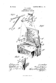
- FIG. l is a broken perspective view of a dresser and drapery fixtures designed for use in connection therewith; Fig. 2, a perspective view of one portion of the hanger shown in Fig. l, in reversed position; and Fig. 3, a broken rear perspective view of the dresser and one of the bracket arms connected therewith.
- A represents a dresser equipped with standards A supporting a mirror A B, a pair of bracket arms connected with the standards A; B a hanger having an adjustable bracket-arm B and B drapery, or a throw, supported by the bracket-arms B, B
- Each bracket-arm B comprises a forwardly projecting arm b terminating in an ornamental end I), and an inturned end b forming substantially a right-angle with the arm b.
- Each arm b is provided with a series of screw-receiving perforations b and each arm is connected with a standard A by screws 1).
- Each arm I) is provided with nicks, or cuts, 1), enabling the arm to be broken off so as not to interfere with the mirror when the bracket-arms B are adjusted to lessen:the distance between them.
- the hanger comprises preferably a bar I) equipped at its upper end with a hook I) and provided with a plurality of perforations b and the bracket B having a horizontal member b and a brace member b
- the member I) has an ornamental front end I) and is equipped at its rear end with a loop b slidable upon the vertical member I).
- the brace member b has a vertical portion b at its lower inner end which is adapted to bear against the vertical member b and which is equipped with a stud 1) adapted to enter any desired one of the perforations b
- the hook b is shown in engagement with the molding C of a chamber wall.
- the member b may be supported on a hook, or it may be secured at its lower end by means of screws to the upper portion of the mirror frame.
- a hanger for the purpose set forth comprising a vertical member provided at its upper end with a molding hook and having a plurality of perforations, and a bracket comprising a horizontal member slidably connected with said vertical member and a brace-member having a pin adapted to enter any desired perforation.
Landscapes
- Engineering & Computer Science (AREA)
- General Engineering & Computer Science (AREA)
- Display Racks (AREA)
Description
PATENTED JULY 23, 1907.
} Vi ill i I I liii lll T..F.BYRON. DRAPERY FIXTURE. APPLICATION FILED JULY 10, 1906 Inn .....ii'!ii UNITED STATES PATENT OFFICE.
THOMAS 1*. BYRON, OF CHICAGO, ILLINOIS, ASSIGNOR OF ONE-HALF TO WILLIAM B. LEDDY, OF CHICAGO, ILLINOIS.
DRAPERY-FIXTURE.
Specification of Letters Patent.
Patented July 23, 1907.
Application filed July 10, 1905. Serial No. 263,950.
To all whom it may concern:
Be it known that I, 'lHoMAs F. BYRON, a citizen of the United States, residing at Chicago, in the county of Cook and State of Illinois, have invented a new and useful Drapery-Fixture, of which the following is a l specification.
My invention relates particularly to drapery fixtures adapted for use in connection with dressers, and the like; and my primaryobject is to provide cheap and simple fixtures which may be readily employed without injury to the chamber walls.
My invention is illustrated in its prefeired embodiment in the accompanying drawing, in which- Figure l is a broken perspective view of a dresser and drapery fixtures designed for use in connection therewith; Fig. 2, a perspective view of one portion of the hanger shown in Fig. l, in reversed position; and Fig. 3, a broken rear perspective view of the dresser and one of the bracket arms connected therewith.
In the drawing, A represents a dresser equipped with standards A supporting a mirror A B, a pair of bracket arms connected with the standards A; B a hanger having an adjustable bracket-arm B and B drapery, or a throw, supported by the bracket-arms B, B
Each bracket-arm B comprises a forwardly projecting arm b terminating in an ornamental end I), and an inturned end b forming substantially a right-angle with the arm b. Each arm b is provided with a series of screw-receiving perforations b and each arm is connected with a standard A by screws 1). Each arm I) is provided with nicks, or cuts, 1), enabling the arm to be broken off so as not to interfere with the mirror when the bracket-arms B are adjusted to lessen:the distance between them.
The hanger comprises preferably a bar I) equipped at its upper end with a hook I) and provided with a plurality of perforations b and the bracket B having a horizontal member b and a brace member b The member I) has an ornamental front end I) and is equipped at its rear end with a loop b slidable upon the vertical member I). The brace member b has a vertical portion b at its lower inner end which is adapted to bear against the vertical member b and which is equipped with a stud 1) adapted to enter any desired one of the perforations b Thus, ready adjustment of the bracket B is provided for. In the illustration shown, the hook b is shown in engagement with the molding C of a chamber wall. However, the member b may be supported on a hook, or it may be secured at its lower end by means of screws to the upper portion of the mirror frame.
It will be observed that different effects in the drapery may be secured by adjusting the brackets B and the bracket B with relation to each other.
What I regard as new, and desire to secure by Letters Patent, is
A hanger for the purpose set forth, comprising a vertical member provided at its upper end with a molding hook and having a plurality of perforations, and a bracket comprising a horizontal member slidably connected with said vertical member and a brace-member having a pin adapted to enter any desired perforation.
THOMAS F. BYRON.
In the presence of L. HEISLAR, J. H. LANDES.
Priority Applications (1)
| Application Number | Priority Date | Filing Date | Title |
|---|---|---|---|
| US26895005A US860963A (en) | 1905-07-10 | 1905-07-10 | Drapery-fixture. |
Applications Claiming Priority (1)
| Application Number | Priority Date | Filing Date | Title |
|---|---|---|---|
| US26895005A US860963A (en) | 1905-07-10 | 1905-07-10 | Drapery-fixture. |
Publications (1)
| Publication Number | Publication Date |
|---|---|
| US860963A true US860963A (en) | 1907-07-23 |
Family
ID=2929415
Family Applications (1)
| Application Number | Title | Priority Date | Filing Date |
|---|---|---|---|
| US26895005A Expired - Lifetime US860963A (en) | 1905-07-10 | 1905-07-10 | Drapery-fixture. |
Country Status (1)
| Country | Link |
|---|---|
| US (1) | US860963A (en) |
-
1905
- 1905-07-10 US US26895005A patent/US860963A/en not_active Expired - Lifetime
Similar Documents
| Publication | Publication Date | Title |
|---|---|---|
| US1107686A (en) | Hanger for picture-frames. | |
| US1017153A (en) | Bed-protector. | |
| US860963A (en) | Drapery-fixture. | |
| US993753A (en) | Shelf-support. | |
| US2534491A (en) | Drapery fixture | |
| US1119695A (en) | Window-fixture. | |
| US430377A (en) | Support for picture or other frames | |
| US358626A (en) | Device for attaching splasher-mats to wash-stands | |
| US887647A (en) | Shade-bracket and curtain-pole supporter. | |
| US309980A (en) | Adjustable picture-hanger | |
| US1115492A (en) | Extension-rod. | |
| US1943666A (en) | Picture frame support | |
| US1172260A (en) | Window-bracket. | |
| US1087611A (en) | Curtain-fixture. | |
| US2472220A (en) | Combination shade and curtain rod holder | |
| US1226019A (en) | Picture-hanger. | |
| US675154A (en) | Picture-hanging device. | |
| US786468A (en) | Curtain and drapery support. | |
| US1347009A (en) | Wall-molding hanger for bird-cages, &c. | |
| US355449A (en) | clark | |
| US841574A (en) | Flower-stand. | |
| US984563A (en) | Lantern-holder for vehicles. | |
| US807257A (en) | Shelf-support. | |
| US627041A (en) | Curtain-support | |
| US1609837A (en) | Picture hanger |