US856463A - Box for watch-movements. - Google Patents
Box for watch-movements. Download PDFInfo
- Publication number
- US856463A US856463A US31922706A US1906319227A US856463A US 856463 A US856463 A US 856463A US 31922706 A US31922706 A US 31922706A US 1906319227 A US1906319227 A US 1906319227A US 856463 A US856463 A US 856463A
- Authority
- US
- United States
- Prior art keywords
- box
- spring
- watch
- watch movement
- arms
- Prior art date
- Legal status (The legal status is an assumption and is not a legal conclusion. Google has not performed a legal analysis and makes no representation as to the accuracy of the status listed.)
- Expired - Lifetime
Links
- 239000011324 bead Substances 0.000 description 12
- 238000010276 construction Methods 0.000 description 2
- 230000004048 modification Effects 0.000 description 2
- 238000012986 modification Methods 0.000 description 2
- 208000027418 Wounds and injury Diseases 0.000 description 1
- 230000006378 damage Effects 0.000 description 1
- 230000000694 effects Effects 0.000 description 1
- 208000014674 injury Diseases 0.000 description 1
- 239000002184 metal Substances 0.000 description 1
- 230000035939 shock Effects 0.000 description 1
Images
Classifications
-
- B—PERFORMING OPERATIONS; TRANSPORTING
- B65—CONVEYING; PACKING; STORING; HANDLING THIN OR FILAMENTARY MATERIAL
- B65D—CONTAINERS FOR STORAGE OR TRANSPORT OF ARTICLES OR MATERIALS, e.g. BAGS, BARRELS, BOTTLES, BOXES, CANS, CARTONS, CRATES, DRUMS, JARS, TANKS, HOPPERS, FORWARDING CONTAINERS; ACCESSORIES, CLOSURES, OR FITTINGS THEREFOR; PACKAGING ELEMENTS; PACKAGES
- B65D85/00—Containers, packaging elements or packages, specially adapted for particular articles or materials
- B65D85/30—Containers, packaging elements or packages, specially adapted for particular articles or materials for articles particularly sensitive to damage by shock or pressure
- B65D85/38—Containers, packaging elements or packages, specially adapted for particular articles or materials for articles particularly sensitive to damage by shock or pressure for delicate optical, measuring, calculating or control apparatus
- B65D85/40—Containers, packaging elements or packages, specially adapted for particular articles or materials for articles particularly sensitive to damage by shock or pressure for delicate optical, measuring, calculating or control apparatus for watches or clocks; for components thereof
Definitions
- CONNECTICUT A CORPORATION OF CONNECTICUT.
- the object of this invention is to provide a box or casing for holding a watch movement boX in a cushioned manner so as to prevent undue jarring or shaking of the watch movement box in transportation and handling.
- the invention consists of a box, preferably of thin sheet metal, having a base or body portion provided with a spring having members which grip and center the watch Inovement box, and other members serving as auxiliary supporting springs, and a top or cover member having a spring which engages the top of the watch movement box, so that the watch movement box is supported in the outer box in a cushioned manner and with a degree of security that will prevent the undue jarring and shaking of the Watch movement box while being transported and handled; and itis preferred to provide the body portion with means whereby the watch movement box will be directed into engagement with and guarded 'from damaging the spring; and the body member' and the cover member have any suitable means, such as bayonet joints, providing for the locking of these two parts, all as we will proceed now more particularly to set forth and finally claim.
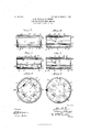
- Figure 1 is a cross-section of the box taken in the plane of the line A-B, Fig. 3, and showing the Watch movement box in place in elevation.
- Fig. 2 is a cross-section taken in the plane of line C-D, Fig. 3, and omitting the watch movement box.
- Fig. 3 is a top plan view of the body member.
- Fig. 4 is a transverse section of a modification taken in the plane of line E-F, Fig. 6.
- Fig. 5 is a crosssection taken in the plane of line G-Ifl, Fig. 6.
- Fig. 6 is a top plan view of the body member of the modification shown in Figs. 4 and 5.
- 1 is the body member having the outwardly projecting circumferential knurled bead 2, and the inwardly projecting bead 3, the former serving not only to strengthen the box but also affording a convenient hand hold for use in applying and removing the cover.
- a many-armed spring L1 In the bottom of the body is fixed a many-armed spring L1, the arms 5 of which are riveted to the bottom by rivets 6, and have their outer ends 7 turned up substantially at right angles and bent inwardly at S, so as to grip the bottom of the watch movement box 9 to hold it in place, with a spring pressure, within the body of the outer box; and the arms 10 of the spring #l are bent upwardly and at an incline to the bottom, and have terminal lips 11 also to engage the edge of the watch movement box, the said arms 10 exerting an upward spring pressure upon the watch movement box.
- These arms 10 are not riveted to the bottom of the body of the box, but are free to exert their resilience upon the watch movement box.
- the riveted arms 5 are resilient in their outer ends only, and that the arms 1() are springs throughout their length and consequently these arms 10 force the movement box into the grasp of the ends 7 against the resistance of saidv ends and thereby hold the movement box within the grasp of the spring in a very firm manner.
- the inwardly projecting bead 3 overhangs the upper edge of the ends 7 of the spring arms 5, (which ends 7, for convenience, are herein referred to as grips"), so as to guard these grips from fouling with the watch movement box when the latter is inserted in the body of the box, and this guarding of these grips is particularly useful when for any reason the grips become out of shape and would thus tend to prevent the watch movement box from being properly seated in the spring.
- the overhanging bead practically prevents the distortion of the grips 7. It will be understood that this bead 3 in el'l'ect guides the movement box directly into engagement with these grips.
- the cover 12 is adapted to telescope over the body, and within its top is arranged a many-armed, preferably four-armed, spring 13, having its arms downwardly inclined and their ends 14 bent over slightly so as to insure .lOO
- This spring 13 is centrally riveted to the cover at 15, as shown in Fig. 2.
- the cover is provided with a circumferential outwardly projecting knurled bead 16 to cogperate with the bead 2 in manipulating the By means of the grips 7 and the bent ends 14 of the cover spring, the watch movement box is centered within the outer box and thus held out of contact with the outer box.
- rivets 6 are spaced quite far apart, and are fixed in the gripping arms, and thus serve to reinforce these arms against the strain imposed upon them in withdrawing the movenzent box from them.
- the body member and the cover member are respectively provided with lugs 1S and grooves 19 1n any desired number, which constitute bayonet joints for locking the two parts together; and when the two parts are so locked together their springs exert sufficient pressure upon the contained watch movement box to hold it in position, center it, and preserve it from the ill effects of any shocks or jars to which it may be exposed.
- guard bead 3 or 17 While we prefer to use the guard bead 3 or 17, the invention is not limited to that use.
- the device is in reality a box or casing for the watch movement box.
- a box for watch movements composed of telescoping members, the lower member provided with a spring having parts rigidly fixed to the bottom of said member and provided With springy outer ends to grip the movement box, said spring having other parts freely movable to support the movement box yieldingly, and the upper member provided with a spring bearing upon the upper portion of the movement box.
- a box for watch movements composed of telescoping members, the lower member having a many-armed spring constructed with box-grasping arms rigidly fixed to the bottom of the said lower member and having resilient outer ends, and yielding box-supporting arms serving to force the box into the grip of the grasping arms, and the upper vmember having a spring to bear upon the upper portion of the movement box, these two springs serving to center the movement box within the casing.
- a box for containing a watch movement box consisting essentially of a casing composed of telescoping members, the lower member having a many-armed spring constructed With box-grasping arms rigidly fixed to the bottom of the said lower member and having resilient outer ends, and yielding boxsupporting arms serving to force the box into the grip of the grasping arms, and the upper member having a spring to bear upon the upper portion of the movement box, these two springs serving to center the movement box within the casing, and the two casing members provided with interlocking means to positively unite them about the movement box.
- a watch movement box casing comprising a body portion containing a manyarmed spring, some of the arms riveted to the body portion and provided with grips and the others free and utilized as springs, respectively to grip and yieldingly support a watch movement box, and a cover member provided with a spring having downwardly deflecting ends to yieldingly engage the watch movement box, and means to lock the two parts together.
- a watch movement box easing,v having a body portion containing a many-armed spring, some of the arms provided with grips and riveted Ato the body portion and the others free and utilized as springs, respectively to grip and yieldingly support a watch movement box, and a cover coperating with the body portion.
- a Watch movement box casing having a body portion containing a many-armed spring, some of the arms provided with grips and the others utilized as springs, respectively to grip and yieldingly support a watch movement box, a guard bead located in'said body portion adjacent to the upper ends of the grips and covering the said ends of the grips to shield them from injury by an incoming box, and a cover for the body portion.
- a watch movement box casing having a body portion containing a many-armed spring, some of the arms provided with grips and the others utilized as springs, respectively to grip and yieldingly support a watch movement box, an inwardly projecting guard bead located immediately above the grips, and a cover for the body portion.
Landscapes
- Engineering & Computer Science (AREA)
- Mechanical Engineering (AREA)
- Clamps And Clips (AREA)
Description
No. 856,463. PATENTED JUNE 1l, 1907. J. H. GOSS & A. F. WOLFF.
BOX FOR WATCH MOVMBNTS. APPLICATION FILED MAY2B.1906.
anun u,
ru: Naam: PETERS cowAsH1NoroN.'o.c
`UNITED STATES PATENT OFFICE. l
JOHN H. GOSS AND ADRIAN F. WOLFF, OF WATERBURY, CONNECTICUT,
ASSIGNORS TO SCOVILL MANUFACTURING COMPANY, OF WATERBURY,
CONNECTICUT, A CORPORATION OF CONNECTICUT.
BOX FOR WATCH-MOVEMENTS.
Specification of Letters Patent.
Patented June 11, 1907.
Application filed May 28,1906. Serial No. 319,227.
To all whom 7115 may concern.-
Be it known that we, JOHN I'I. Goss and ADRIAN F. WOLFF, citizens of the United States, residing at Waterbury, in the county of New Haven and State of Connecticut, have invented a certain new and useful Improvement in Boxes -for Vatch-ltlovements, of which the following is a full, clear, and exact description.
The object of this invention is to provide a box or casing for holding a watch movement boX in a cushioned manner so as to prevent undue jarring or shaking of the watch movement box in transportation and handling.
The invention consists of a box, preferably of thin sheet metal, having a base or body portion provided with a spring having members which grip and center the watch Inovement box, and other members serving as auxiliary supporting springs, and a top or cover member having a spring which engages the top of the watch movement box, so that the watch movement box is supported in the outer box in a cushioned manner and with a degree of security that will prevent the undue jarring and shaking of the Watch movement box while being transported and handled; and itis preferred to provide the body portion with means whereby the watch movement box will be directed into engagement with and guarded 'from damaging the spring; and the body member' and the cover member have any suitable means, such as bayonet joints, providing for the locking of these two parts, all as we will proceed now more particularly to set forth and finally claim.
In the accompanying drawings, illustrating the invention, in the several figures of which like parts are similarly designated, Figure 1 is a cross-section of the box taken in the plane of the line A-B, Fig. 3, and showing the Watch movement box in place in elevation. Fig. 2 is a cross-section taken in the plane of line C-D, Fig. 3, and omitting the watch movement box. Fig. 3 is a top plan view of the body member. Fig. 4 is a transverse section of a modification taken in the plane of line E-F, Fig. 6. Fig. 5 is a crosssection taken in the plane of line G-Ifl, Fig. 6. Fig. 6 is a top plan view of the body member of the modification shown in Figs. 4 and 5.
Referring to Figs. 1, 2 and 3, 1 is the body member having the outwardly projecting circumferential knurled bead 2, and the inwardly projecting bead 3, the former serving not only to strengthen the box but also affording a convenient hand hold for use in applying and removing the cover. In the bottom of the body is fixed a many-armed spring L1, the arms 5 of which are riveted to the bottom by rivets 6, and have their outer ends 7 turned up substantially at right angles and bent inwardly at S, so as to grip the bottom of the watch movement box 9 to hold it in place, with a spring pressure, within the body of the outer box; and the arms 10 of the spring #l are bent upwardly and at an incline to the bottom, and have terminal lips 11 also to engage the edge of the watch movement box, the said arms 10 exerting an upward spring pressure upon the watch movement box. These arms 10 are not riveted to the bottom of the body of the box, but are free to exert their resilience upon the watch movement box. It will be observed that the riveted arms 5 are resilient in their outer ends only, and that the arms 1() are springs throughout their length and consequently these arms 10 force the movement box into the grasp of the ends 7 against the resistance of saidv ends and thereby hold the movement box within the grasp of the spring in a very firm manner.
The inwardly projecting bead 3 overhangs the upper edge of the ends 7 of the spring arms 5, (which ends 7, for convenience, are herein referred to as grips"), so as to guard these grips from fouling with the watch movement box when the latter is inserted in the body of the box, and this guarding of these grips is particularly useful when for any reason the grips become out of shape and would thus tend to prevent the watch movement box from being properly seated in the spring. As a matter of factJ the overhanging bead practically prevents the distortion of the grips 7. It will be understood that this bead 3 in el'l'ect guides the movement box directly into engagement with these grips.
The cover 12 is adapted to telescope over the body, and within its top is arranged a many-armed, preferably four-armed, spring 13, having its arms downwardly inclined and their ends 14 bent over slightly so as to insure .lOO
firm .engagement with the top of the watch movement box 9. This spring 13 is centrally riveted to the cover at 15, as shown in Fig. 2.
The cover is provided with a circumferential outwardly projecting knurled bead 16 to cogperate with the bead 2 in manipulating the By means of the grips 7 and the bent ends 14 of the cover spring, the watch movement box is centered within the outer box and thus held out of contact with the outer box.
Referring to the construction shown in Figs. 4, 5, and 6, all of the parts are as in the previously described construction and are similarly designated, except that the guard bead 17 projects outwardly and the grips 7 extend sufficiently far into this bead to be protected by it from distortion by the entrance of the movement box.
It will be observed that the rivets 6 are spaced quite far apart, and are fixed in the gripping arms, and thus serve to reinforce these arms against the strain imposed upon them in withdrawing the movenzent box from them.
As shown in Figs. 2, 4 and 5, the body member and the cover member are respectively provided with lugs 1S and grooves 19 1n any desired number, which constitute bayonet joints for locking the two parts together; and when the two parts are so locked together their springs exert sufficient pressure upon the contained watch movement box to hold it in position, center it, and preserve it from the ill effects of any shocks or jars to which it may be exposed.
While we prefer to use the guard bead 3 or 17, the invention is not limited to that use.
As already sufficiently indicated, while the invention is entitled a watch movement box, the device is in reality a box or casing for the watch movement box.
What we claim is z- 1. A box for watch movements, composed of telescoping members, the lower member provided with a spring having parts rigidly fixed to the bottom of said member and provided With springy outer ends to grip the movement box, said spring having other parts freely movable to support the movement box yieldingly, and the upper member provided with a spring bearing upon the upper portion of the movement box.
2. A box for watch movements, composed of telescoping members, the lower member having a many-armed spring constructed with box-grasping arms rigidly fixed to the bottom of the said lower member and having resilient outer ends, and yielding box-supporting arms serving to force the box into the grip of the grasping arms, and the upper vmember having a spring to bear upon the upper portion of the movement box, these two springs serving to center the movement box within the casing.
3. A box for containing a watch movement box, consisting essentially of a casing composed of telescoping members, the lower member having a many-armed spring constructed With box-grasping arms rigidly fixed to the bottom of the said lower member and having resilient outer ends, and yielding boxsupporting arms serving to force the box into the grip of the grasping arms, and the upper member having a spring to bear upon the upper portion of the movement box, these two springs serving to center the movement box within the casing, and the two casing members provided with interlocking means to positively unite them about the movement box.
4. A watch movement box casing, comprising a body portion containing a manyarmed spring, some of the arms riveted to the body portion and provided with grips and the others free and utilized as springs, respectively to grip and yieldingly support a watch movement box, and a cover member provided with a spring having downwardly deflecting ends to yieldingly engage the watch movement box, and means to lock the two parts together.
5. A watch movement box easing,v having a body portion containing a many-armed spring, some of the arms provided with grips and riveted Ato the body portion and the others free and utilized as springs, respectively to grip and yieldingly support a watch movement box, and a cover coperating with the body portion. A
6. A Watch movement box casing, having a body portion containing a many-armed spring, some of the arms provided with grips and the others utilized as springs, respectively to grip and yieldingly support a watch movement box, a guard bead located in'said body portion adjacent to the upper ends of the grips and covering the said ends of the grips to shield them from injury by an incoming box, and a cover for the body portion.
7. A watch movement box casing, having a body portion containing a many-armed spring, some of the arms provided with grips and the others utilized as springs, respectively to grip and yieldingly support a watch movement box, an inwardly projecting guard bead located immediately above the grips, and a cover for the body portion.
In testimony whereof we have hereunto set our hands this 25th day of May A. D.
JOHN H. GOSS. ADRIAN F. WOLFF. 'Witnessesz J. H. PILLING, HENRY FEHL.
IOO
Priority Applications (1)
| Application Number | Priority Date | Filing Date | Title |
|---|---|---|---|
| US31922706A US856463A (en) | 1906-05-28 | 1906-05-28 | Box for watch-movements. |
Applications Claiming Priority (1)
| Application Number | Priority Date | Filing Date | Title |
|---|---|---|---|
| US31922706A US856463A (en) | 1906-05-28 | 1906-05-28 | Box for watch-movements. |
Publications (1)
| Publication Number | Publication Date |
|---|---|
| US856463A true US856463A (en) | 1907-06-11 |
Family
ID=2924918
Family Applications (1)
| Application Number | Title | Priority Date | Filing Date |
|---|---|---|---|
| US31922706A Expired - Lifetime US856463A (en) | 1906-05-28 | 1906-05-28 | Box for watch-movements. |
Country Status (1)
| Country | Link |
|---|---|
| US (1) | US856463A (en) |
Cited By (3)
| Publication number | Priority date | Publication date | Assignee | Title |
|---|---|---|---|---|
| US2780348A (en) * | 1954-02-18 | 1957-02-05 | Eastman Kodak Co | Container for photographic objectives, filters, supplementary lenses, and the like |
| US3552548A (en) * | 1968-08-05 | 1971-01-05 | Fluroware Inc | Wafer storage and shipping container |
| US3700097A (en) * | 1971-01-11 | 1972-10-24 | Bendix Corp | Shipping container for fragile articles |
-
1906
- 1906-05-28 US US31922706A patent/US856463A/en not_active Expired - Lifetime
Cited By (3)
| Publication number | Priority date | Publication date | Assignee | Title |
|---|---|---|---|---|
| US2780348A (en) * | 1954-02-18 | 1957-02-05 | Eastman Kodak Co | Container for photographic objectives, filters, supplementary lenses, and the like |
| US3552548A (en) * | 1968-08-05 | 1971-01-05 | Fluroware Inc | Wafer storage and shipping container |
| US3700097A (en) * | 1971-01-11 | 1972-10-24 | Bendix Corp | Shipping container for fragile articles |
Similar Documents
| Publication | Publication Date | Title |
|---|---|---|
| US856463A (en) | Box for watch-movements. | |
| US1228813A (en) | Device for supporting pails or the like. | |
| US784513A (en) | Cap-fastening for vessels. | |
| US989213A (en) | Rule-holder. | |
| US545641A (en) | Pencil-holder | |
| US567488A (en) | Vial for soluble tablets | |
| US515369A (en) | Henry rowland saunders | |
| US777713A (en) | Demijohn. | |
| US1247355A (en) | Milk-can carrier. | |
| US1139365A (en) | Straw-holder. | |
| US1228706A (en) | Collapsible drinking-cup. | |
| US825372A (en) | Combined match-box and oil-can. | |
| US378907A (en) | johnp | |
| US2536144A (en) | Inkstand | |
| US1277838A (en) | Liquid-container support. | |
| US896228A (en) | Hand-truck. | |
| US726505A (en) | Bottle-stoppering apparatus. | |
| US1216023A (en) | Cover-fastening means for a garbage-receptacle. | |
| US1212406A (en) | Lamp-holder. | |
| US848643A (en) | Whip-socket. | |
| US459598A (en) | Holder for can-covers | |
| US1156579A (en) | Bobbin. | |
| US1154973A (en) | Bottle-cover. | |
| US903071A (en) | Device for manipulating cut-glass articles. | |
| US817149A (en) | Tray for glasses. |