US856435A - Pressed-steel car. - Google Patents
Pressed-steel car. Download PDFInfo
- Publication number
- US856435A US856435A US31195606A US1906311956A US856435A US 856435 A US856435 A US 856435A US 31195606 A US31195606 A US 31195606A US 1906311956 A US1906311956 A US 1906311956A US 856435 A US856435 A US 856435A
- Authority
- US
- United States
- Prior art keywords
- plates
- beams
- car
- construction
- rivets
- Prior art date
- Legal status (The legal status is an assumption and is not a legal conclusion. Google has not performed a legal analysis and makes no representation as to the accuracy of the status listed.)
- Expired - Lifetime
Links
- 229910000831 Steel Inorganic materials 0.000 title description 16
- 239000010959 steel Substances 0.000 title description 16
- 238000010276 construction Methods 0.000 description 34
- 238000005266 casting Methods 0.000 description 10
- 238000000034 method Methods 0.000 description 5
- RTZKZFJDLAIYFH-UHFFFAOYSA-N Diethyl ether Chemical compound CCOCC RTZKZFJDLAIYFH-UHFFFAOYSA-N 0.000 description 4
- 238000000465 moulding Methods 0.000 description 3
- 229910001369 Brass Inorganic materials 0.000 description 2
- XEEYBQQBJWHFJM-UHFFFAOYSA-N Iron Chemical compound [Fe] XEEYBQQBJWHFJM-UHFFFAOYSA-N 0.000 description 2
- 239000004411 aluminium Substances 0.000 description 2
- 229910052782 aluminium Inorganic materials 0.000 description 2
- XAGFODPZIPBFFR-UHFFFAOYSA-N aluminium Chemical compound [Al] XAGFODPZIPBFFR-UHFFFAOYSA-N 0.000 description 2
- 239000010951 brass Substances 0.000 description 2
- CWYNVVGOOAEACU-UHFFFAOYSA-N Fe2+ Chemical compound [Fe+2] CWYNVVGOOAEACU-UHFFFAOYSA-N 0.000 description 1
- 229910001296 Malleable iron Inorganic materials 0.000 description 1
- UIQWBVPFHHQZHH-UHFFFAOYSA-N OOOOOOOOOOOOOO Chemical compound OOOOOOOOOOOOOO UIQWBVPFHHQZHH-UHFFFAOYSA-N 0.000 description 1
- 241000610743 Psathyrotes ramosissima Species 0.000 description 1
- 238000005452 bending Methods 0.000 description 1
- 230000002708 enhancing effect Effects 0.000 description 1
- 229910052742 iron Inorganic materials 0.000 description 1
- 230000007775 late Effects 0.000 description 1
- 239000002184 metal Substances 0.000 description 1
- 229910052751 metal Inorganic materials 0.000 description 1
- 238000004080 punching Methods 0.000 description 1
Images
Classifications
-
- B—PERFORMING OPERATIONS; TRANSPORTING
- B61—RAILWAYS
- B61D—BODY DETAILS OR KINDS OF RAILWAY VEHICLES
- B61D17/00—Construction details of vehicle bodies
- B61D17/04—Construction details of vehicle bodies with bodies of metal; with composite, e.g. metal and wood body structures
- B61D17/08—Sides
Definitions
- My improvements relate to the construc tion of passenger coaches for railway use, made from steel plates properly riveted towith metallic girders, and beams, so that the car may be constructed entirely of steel, and the purpose of the invention is to provide a construction much simpler, and obviating the necessity of cutting and fitting the parts to follow the'design of wooden car construction, as is the practice of car builders at the present time.
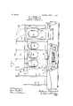
- Figure l is a side elevation of one end of a passenger coach of my improved construction, with parts of same broken away.
- Fig. 2 is a side elevation of a the car, showing the method ofsetting up in place, and riveting together.
- Fig. 3 the construction shown in Fig. 2.
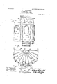
- Fig. 4 is an end elevation of two of the side plates riv- Fig.5 is a vertical cross section of 'alf of the car.
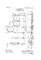
- Fig. 6 is a side elevation of one of the plates for the side- Fig. 7
- FIG. 8 is an end elevation of one inside and one out-- 35 side plate, showing the method of flangin same for riveting to ether.
- Figs. 8, 9 an 10 are perspective views bf the side beams, illustratingtlie method of forming the rivets on. the beams.
- Figs. 11 and 12 are erspective cross sectional views of a modi ed form gs. 13'and 14 are transverse and vertical 'sectlons through the I-beam, showing the method of riveting the sills to the beams.
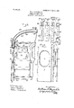
- Fig. 15 is a side elevation of one end. of the car, showi the construction of the hood for the roof.
- ig. 16 is a plan view of the hood construction.
- the plates are then put on a specially designed punch, and all the rivet holes 4 in the circular flange, and the side rows of lIVGt holes 6'6 along the side edges of the plates, are all punched at one operation.
- These plates are made up in pairs, exactly al ke, one for the outside, and one for the inside wall of the car, and the circular flange on one of these plates, preferably the inside plate,
- I provide two longitudinal or side sill plates 89, which runthe entire length of the car, and by rivets IO IO I rivet the upright beams or osts 12 thereto at the bottom.
- beams are substantially I-beams, and the riveting of same to the longitudinal sill plates is accomplished through the flanges 13 of these beams, or as a preferable construction,
- a suitable number of floor beams or girders 21 are then riveted to the sills by means of the angle plates 22, and these floor beams are also preferably of the K-beam construction, but without the rivets formed thereon, and the floor beams are of the proper length for the width of the car.
- My framework having been thus constructed, the iri'side and outside plates 1 1 which have been previously riveted together as described, arelthen lowered into position over the side beams 12, the side edges of these plates being sprung out as shown at in Fig. 3, so as to pass over the rivets 17 on the beams, one plate overlapping the adjoining plates both inside andoutside, and then the sides plates are bent back and riveted to the beams, one set of rivets being all that is required to rivet the two adjoining overlapping plates to the side beams.
- roof beams 01? car lines are riveted in place.
- These roof beams 24 are of the same construction as the side beams eXcept that they are curved to form an oval or turtle back roof, and are somewhat lighter in weight and size than the side beams as they are not required to carry any strain, except the holding of the roof, and the spacing of the sides.
- the rivets on these roof beams are formed in the same way as they are in connection with the side beams, these beams are bolted or riveted to the upper ends of the side beams by the plates 25.
- the roof and ceiling plates 26-27 are riveted to these ear lines, or roof beams, in the same T way as the sides, the plates running entirely across the roof, and being in width about equal to the'distance of four or five side beams.
- the outside plates are first riveted on, and then the ceiling plates.
- letter board plates 28 and transom plates 29' are riveted in place at the top of the side plates.
- the roof plates 26 overlap the upper edge of the letter board plate, and the edges of same are secured by a finish molding running longitudinally, and screwed in place.
- the ceiling plates are riveted in place last of all, and the joint between the ceiling plates and this inside plate is concealed by a metal molding 30.
- window frames Ipropose to use a frame work of aluminium or brass 31to fit the opening formed as a window opening in the side plates, which frame will cover the rivet heads in the window section, and, in this frame, is mounted the stationary windowfj'l and a movable window 33, which can be 1 d open the window b drawing in .l) ⁇ -: 1' end of the window sash, and dropping same into the pocket 34 between theseats.
- the shade roller 35 is mounted above thewindow on the inside of the car, in a metallic case, which case has extensions 37 that reach to the bottom of the windows, and said extensions 37 cover the rivet heads of the plate joints inside the car, and also have grooves on the inner sides of same to guide the curtain to the bottom of the window, and to retain same inposition, and carries the shade roller 35 for the window.
- the beams 44 for the hood car lines are constructedin the same way that the side posts and main roof car lines are constructed with the rivets 46, formed integrally as 'hereinbefore described on the top of the beams.
- Each of the hood beams may be formed with these rivets or some of them may beprovided without the rivets, as illustrated in the drawings, so as to form mere supports and give shape to the hood construction.
- the inside and outside plates could be first riveted to the beams, and then the window flanges riveted together, but as this method would be much more tedious than first riveting the plates together by the Window flanges, I much prefer the former construction.
- Iii a steel car construction, plates for the side walls, consisting of an inside and an outside plate, with flanged window openings, said plates being secured together by rivets through the flanges, substantially as described.
- plates for the side walls consisting of an inside and an outside'plate, with flanged window openings, the flange of one plate overlapping the flange of its corresponding plate, and rivets for securing the overlapping flanges together, substantially as described.
- plates for the side walls consisting of an inside and an outside plate, With'flanged window openings formed oval in shape, the flange of one plate overlapping the flange of its corresponding plate, with rivet-s for securing the overlapping flanges together, scribed.
- plates for the side walls consisting of an inside and an outside plate, with flanged window openings
- said plates being secured together by rivets through the flanges, and window frame castings to serve as frames for the window sashes, and to cover the rivets at the window openings.
- side beams for the framework having a vertical row of rivets formed integral therewith on each side edge, and inside and outside plates secured together and passed over said rivets, said lates overlapping each other, with the overap ing edges secured to said beams, and to eac 1 other by said rivets.
- side beams for the framework having a vertical row of rivets formed integral therewith, and side plates consisting of an inside and an outside plate, with flanged window openings, .said plat-cs being secured together by rivets through the flanges, and with their side edges overla ping and secured to said beams, and to eac 1 other, by said integral rivets on the beams.
- beams for securing the plates to the framework 01' the car consisting of I-beams with central longitudinal flanges, having sections out therefrom to form rivets for the plates.
- beams for securing the plates to the framework of the car consisting of T-beams with central longitudinal flanges having sections out there-- from to form rivets, and plates overlapping each other with the overlapping edges secured on said rivets, substantially as de scribed.
- a casting provided with wings or lugs, with curved beams, secured thereto, extending radially therefrom to form a frame for the roof hood.
- a casting provided with radial wings or lugs, said casting secured at the medial portion of said car line, with curved beams secured to said radial wings and extending radially to the top of the side walls to form the framework for the hood.
Landscapes
- Engineering & Computer Science (AREA)
- Life Sciences & Earth Sciences (AREA)
- Wood Science & Technology (AREA)
- Mechanical Engineering (AREA)
- Body Structure For Vehicles (AREA)
Description
No. 856,435. 7 PATENTED JUNE 11, 1907. W. G. WAGENHA'LS.
PRESSED STEEL GAR. APPLICATION FILED A,PR.16.190B.
4 SHEETS-SHEET 2.
ooooooooooo0oooo coo M X/155E51 I vgr;/I'U 944% @033 g J PATENTED JUNE 11', 1907.
m 81 L M AGE H P NB BED GT A u ST -E Rw m P 4 SHEETS-SHEET 3.
Wi F11 E55 125 N0. 856,435. PATENTED JUNE 11, 1907. W. G. WAGENHALS. PRESSED STEEL GAR.
APPLICATION FILED APR. 18, 1906.
4 SHEETS-SHEET 4.
oo'oooooooooooooo cooooooooeo F517 Uzlmmuzlm'n mgmlznzulg wir'nassgs. I Invan Fur-L gether 15 7 portion of one side of eted to ether.
. ofsidebeam. Fi
i UNITED STATES PATENT orrroa. WILLIAM WAGEN HALS, LOUIS, MISSOURI.
PRESSED-STEEL CAR.
Spe cificationof Letters Patent.
Patented June 11, 1907.
Application filed April 16, 1906. Serial No- 311,956.
- panylng drawings, forming part of this specification.
My improvements relate to the construc tion of passenger coaches for railway use, made from steel plates properly riveted towith metallic girders, and beams, so that the car may be constructed entirely of steel, and the purpose of the invention is to provide a construction much simpler, and obviating the necessity of cutting and fitting the parts to follow the'design of wooden car construction, as is the practice of car builders at the present time.
In the drawings Figure l is a side elevation of one end of a passenger coach of my improved construction, with parts of same broken away. Fig. 2 is a side elevation of a the car, showing the method ofsetting up in place, and riveting together. Fig. 3 the construction shown in Fig. 2. Fig. 4 is an end elevation of two of the side plates riv- Fig.5 is a vertical cross section of 'alf of the car. Fig. 6 is a side elevation of one of the plates for the side- Fig. 7
is an end elevation of one inside and one out-- 35 side plate, showing the method of flangin same for riveting to ether. Figs. 8, 9 an 10 are perspective views bf the side beams, illustratingtlie method of forming the rivets on. the beams. Figs. 11 and 12 are erspective cross sectional views of a modi ed form gs. 13'and 14 are transverse and vertical 'sectlons through the I-beam, showing the method of riveting the sills to the beams. Fig. 15 is a side elevation of one end. of the car, showi the construction of the hood for the roof. ig. 16 is a plan view of the hood construction. Fig. 17-shows respectively plan and ontviews of the casti to which the hoo *beams are secured.
n constructing m car, I take steel plates 1 of about one-eight inch in thickness, and of a len' th of the height of the side of the car, an of sufficient width to give whatever window opening may be desired, and I provide as many of these plates as may be neces- 1s.a horizontal section of I punched in the flanges 19 19 o sary for the length of the car. Each plate is then placed in a specially designed press, or stamp, and the oval window opening 2 1s punched therein, the plates are then placed on another press and the edges of the opening bent down into the circular flange 3. The plates are then put on a specially designed punch, and all the rivet holes 4 in the circular flange, and the side rows of lIVGt holes 6'6 along the side edges of the plates, are all punched at one operation. These plates are made up in pairs, exactly al ke, one for the outside, and one for the inside wall of the car, and the circular flange on one of these plates, preferably the inside plate,
'is formed somewhat smaller than the flange on the outside plate, so that one flange can be placed inside the other to overlap, and the two plates are then riveted together with rivets 7, so that the two plates arethus so .cured together.
In forming my frame for the car, I provide two longitudinal or side sill plates 89, which runthe entire length of the car, and by rivets IO IO I rivet the upright beams or osts 12 thereto at the bottom. beams are substantially I-beams, and the riveting of same to the longitudinal sill plates is accomplished through the flanges 13 of these beams, or as a preferable construction,
These I provide special casting 38, as shown in Figs.
13 and 14, and rivet these castings to the central web of the I-beam, and then rivet the sills to the castin s as shown. provide rivets on 51688 upright beams for my side plates, I proceed as illustrated in Figs. 8,9and10. The I-beams 12 are rolled with projecting flanges 14-I5=running lengthwise of the' beam, and the beams are rolled preferably from soft Norway iron, suitable for riveting. The beam is then placed in a special machine, and with dies, sections are. out from the projecting flanges 14 15, leaving the 'square lugs "16-16, and if only square holes are" punched in the side edgesof the side plates, these square lugs may be left as they.
. are, but as I prefer to employ circular rivets,- these square shown at 17, in Fig. 10. Instead of emugs 16 are then rounded up as ploying I-beams for the side beams of the car, I canalso make use of Ube ams or channel beams, as shown at 18 in Figs. 11 and 12, and in this construction openings are In order to the U-bearh and the double headed rivets 2O employed, but I prefer the construction as illustrated in Figs 8, 9 and 10.
Both sides of the car' being made up as above described, a suitable number of floor beams or girders 21 are then riveted to the sills by means of the angle plates 22, and these floor beams are also preferably of the K-beam construction, but without the rivets formed thereon, and the floor beams are of the proper length for the width of the car.
My framework having been thus constructed, the iri'side and outside plates 1 1 which have been previously riveted together as described, arelthen lowered into position over the side beams 12, the side edges of these plates being sprung out as shown at in Fig. 3, so as to pass over the rivets 17 on the beams, one plate overlapping the adjoining plates both inside andoutside, and then the sides plates are bent back and riveted to the beams, one set of rivets being all that is required to rivet the two adjoining overlapping plates to the side beams.
After the sides are constructed, the roof beams 01? car lines are riveted in place. These roof beams 24 are of the same construction as the side beams eXcept that they are curved to form an oval or turtle back roof, and are somewhat lighter in weight and size than the side beams as they are not required to carry any strain, except the holding of the roof, and the spacing of the sides. The rivets on these roof beams are formed in the same way as they are in connection with the side beams, these beams are bolted or riveted to the upper ends of the side beams by the plates 25. The roof and ceiling plates 26-27 are riveted to these ear lines, or roof beams, in the same T way as the sides, the plates running entirely across the roof, and being in width about equal to the'distance of four or five side beams. The outside plates are first riveted on, and then the ceiling plates.
Before riveting the roof plates in place, the
For the window frames, Ipropose to use a frame work of aluminium or brass 31to fit the opening formed as a window opening in the side plates, which frame will cover the rivet heads in the window section, and, in this frame, is mounted the stationary windowfj'l and a movable window 33, which can be 1 d open the window b drawing in .l)\\-: 1' end of the window sash, and dropping same into the pocket 34 between theseats.
33 are aluminium castings. The shade roller 35 is mounted above thewindow on the inside of the car, in a metallic case, which case has extensions 37 that reach to the bottom of the windows, and said extensions 37 cover the rivet heads of the plate joints inside the car, and also have grooves on the inner sides of same to guide the curtain to the bottom of the window, and to retain same inposition, and carries the shade roller 35 for the window.
The construction of the ends of the car, the
side walls of the vestibules, the. door frames,
and the doors, is the same as the construction for the sides of 'the car, but for the hoods over the vestibules, or car ends, I provide as follows, as shown in Figs. 15, 16 and 17.
40 represents the last car line at each end of the car, which runs straight across from one side to the other. To the middle of this car line is bolted by the bolts 43 a semi-circular casting 41 of brass, steel, or malleable iron, ndth lugs 42 cast thereon, and extending out radially from the outside of the cast ing. Holes are cored in these wings or lugs and hood car lines 44 bent to the shape'of the roof required are bolted or riveted to the lugs v42 of the casting 41, and radiate therefrom to the edge beam of the roof to which they are secured by angle plates'45. The beams 44 for the hood car lines are constructedin the same way that the side posts and main roof car lines are constructed with the rivets 46, formed integrally as 'hereinbefore described on the top of the beams. Each of the hood beams may be formed with these rivets or some of them may beprovided without the rivets, as illustrated in the drawings, so as to form mere supports and give shape to the hood construction.
Instead of punching oval openings in the side plates for window openings, rectangular window spaces can be formed, and the flanges riveted together as in the case of the oval openings, but in such construction the corners of the flanges would have to be'cut or severed, and the openings can then be covered by an ornamental molding forming part of the window frame, but I prefer the oval construction as obviating the necessity of severing the flanges.
It will be noticed that with my construction for the sides of the car, I virtually establish a truss bridge of the sides, enabling me to have a lighter floor system, and to carry the floor and roof therefrom, while in the ordinary constructions just the oppositeeffect is the result.
The riveting together of the outside and inside side plates at the window openings, and the riveting of these platesto thefposts gives a rigid side construction without other bracing.
By reason of the construction of my side The sash for the windows 32 and rig riveted, a
beams or osts, to which the side plates are ll unnecessary riveting is avoided, which materially lowers the cost of construction, in addition-to enhancing the appearance of the car by reducing the number of rivet heads.
Instead of riveting the inside and outside plates together by the window flanges, and then bending out the edges of the plates to letthem down over the rivets on the beams, under some conditions, the inside and outside plates could be first riveted to the beams, and then the window flanges riveted together, but as this method would be much more tedious than first riveting the plates together by the Window flanges, I much prefer the former construction.
Having thus described my invention, what- I claim'as new, and desire to secure by Letters Patent, is:
1. Iii a steel car construction, plates for the side walls, consisting of an inside and an outside plate, with flanged window openings, said plates being secured together by rivets through the flanges, substantially as described.
2. In a steel car construction, plates for the side walls, consisting of an inside and an outside'plate, with flanged window openings, the flange of one plate overlapping the flange of its corresponding plate, and rivets for securing the overlapping flanges together, substantially as described.
3. In a steel car construction, plates for the side walls, consisting of an inside and an outside plate, With'flanged window openings formed oval in shape, the flange of one plate overlapping the flange of its corresponding plate, with rivet-s for securing the overlapping flanges together, scribed.
4. In a steel car construction, plates for the side walls, consisting of an inside and an outside plate, with flanged window openings,
said plates being secured together by rivets through the flanges, and window frame castings to serve as frames for the window sashes, and to cover the rivets at the window openings.
5. In a steel car construction, plates for the walls, and beams for holding the same,
substantially as desaid beams provided with a vertical row of rivets formed integral therewith, with the plates passed over said rivets and secured thereon.
6. In a steel car construction, side beams for the framework having a vertical row of rivets formed integral therewith on each side edge, and inside and outside plates secured together and passed over said rivets, said lates overlapping each other, with the overap ing edges secured to said beams, and to eac 1 other by said rivets.
7. In a steel car construction, side beams for the framework having a vertical row of rivets formed integral therewith, and side plates consisting of an inside and an outside plate, with flanged window openings, .said plat-cs being secured together by rivets through the flanges, and with their side edges overla ping and secured to said beams, and to eac 1 other, by said integral rivets on the beams.
8. Ina steel car construction, beams for securing the plates to the framework 01' the car, consisting of I-beams with central longitudinal flanges, having sections out therefrom to form rivets for the plates.
9. In a steel car construction, beams for securing the plates to the framework of the car, consisting of T-beams with central longitudinal flanges having sections out there-- from to form rivets, and plates overlapping each other with the overlapping edges secured on said rivets, substantially as de scribed.
10. In a steel car construction, a casting provided with wings or lugs, with curved beams, secured thereto, extending radially therefrom to form a frame for the roof hood.
11. In a steel car construction, in combi .nation with a transverse car line, a casting provided with radial wings or lugs, said casting secured at the medial portion of said car line, with curved beams secured to said radial wings and extending radially to the top of the side walls to form the framework for the hood.
WILLIAM G. WAGENHALS. Witnesses:
Gno. A. H. MILLS, EDWIN S. MeGnn.
Priority Applications (1)
| Application Number | Priority Date | Filing Date | Title |
|---|---|---|---|
| US31195606A US856435A (en) | 1906-04-16 | 1906-04-16 | Pressed-steel car. |
Applications Claiming Priority (1)
| Application Number | Priority Date | Filing Date | Title |
|---|---|---|---|
| US31195606A US856435A (en) | 1906-04-16 | 1906-04-16 | Pressed-steel car. |
Publications (1)
| Publication Number | Publication Date |
|---|---|
| US856435A true US856435A (en) | 1907-06-11 |
Family
ID=2924890
Family Applications (1)
| Application Number | Title | Priority Date | Filing Date |
|---|---|---|---|
| US31195606A Expired - Lifetime US856435A (en) | 1906-04-16 | 1906-04-16 | Pressed-steel car. |
Country Status (1)
| Country | Link |
|---|---|
| US (1) | US856435A (en) |
Cited By (2)
| Publication number | Priority date | Publication date | Assignee | Title |
|---|---|---|---|---|
| US2502320A (en) * | 1946-08-24 | 1950-03-28 | Marmon Herrington Co Inc | Vehicle body structure |
| US5392717A (en) * | 1992-09-11 | 1995-02-28 | Trinity Industries, Inc. | Railway car |
-
1906
- 1906-04-16 US US31195606A patent/US856435A/en not_active Expired - Lifetime
Cited By (3)
| Publication number | Priority date | Publication date | Assignee | Title |
|---|---|---|---|---|
| US2502320A (en) * | 1946-08-24 | 1950-03-28 | Marmon Herrington Co Inc | Vehicle body structure |
| US5392717A (en) * | 1992-09-11 | 1995-02-28 | Trinity Industries, Inc. | Railway car |
| US5511491A (en) * | 1992-09-11 | 1996-04-30 | Trinity Industries, Inc. | Railway car |
Similar Documents
| Publication | Publication Date | Title |
|---|---|---|
| KR960705709A (en) | Track-bound power car | |
| EP0561369A1 (en) | Construction of structural body | |
| GB544368A (en) | Improvements in or relating to rail cars | |
| US2476451A (en) | Vehicle sheathing arrangement | |
| US856435A (en) | Pressed-steel car. | |
| GB496286A (en) | Improvements in and relating to elevator cars | |
| EP2064103B1 (en) | Rail vehicle roof | |
| US2851965A (en) | Box car | |
| US3461819A (en) | Vehicle body construction and method of making it | |
| US2045291A (en) | Car door | |
| DE19537498C2 (en) | Segmented shell construction with floating inner lining | |
| US2190334A (en) | Railroad car wall construction | |
| US1995532A (en) | Car construction | |
| EP1621675A1 (en) | Element for sound barrier | |
| US2246499A (en) | Car construction | |
| US1031060A (en) | Passenger-car. | |
| DE860220C (en) | Vehicle housing for rail or road operation | |
| US2030748A (en) | Railway car structure | |
| US2244661A (en) | Railway car | |
| GB444513A (en) | Improvements in or relating to railway vehicle bodies | |
| US2044513A (en) | Car body construction | |
| GB504090A (en) | Improvements in or relating to rail cars | |
| US1151468A (en) | Car-roof. | |
| US832487A (en) | Railway-car frame. | |
| US755022A (en) | Steel-frame box-car. |