US8550276B2 - Cylindrical structure made up of rectangular elements - Google Patents
Cylindrical structure made up of rectangular elements Download PDFInfo
- Publication number
- US8550276B2 US8550276B2 US12/447,534 US44753408A US8550276B2 US 8550276 B2 US8550276 B2 US 8550276B2 US 44753408 A US44753408 A US 44753408A US 8550276 B2 US8550276 B2 US 8550276B2
- Authority
- US
- United States
- Prior art keywords
- rectangular pieces
- bottom wall
- sector
- tank according
- panels
- Prior art date
- Legal status (The legal status is an assumption and is not a legal conclusion. Google has not performed a legal analysis and makes no representation as to the accuracy of the status listed.)
- Expired - Fee Related, expires
Links
Images


Classifications
-
- F—MECHANICAL ENGINEERING; LIGHTING; HEATING; WEAPONS; BLASTING
- F17—STORING OR DISTRIBUTING GASES OR LIQUIDS
- F17C—VESSELS FOR CONTAINING OR STORING COMPRESSED, LIQUEFIED OR SOLIDIFIED GASES; FIXED-CAPACITY GAS-HOLDERS; FILLING VESSELS WITH, OR DISCHARGING FROM VESSELS, COMPRESSED, LIQUEFIED, OR SOLIDIFIED GASES
- F17C3/00—Vessels not under pressure
- F17C3/02—Vessels not under pressure with provision for thermal insulation
- F17C3/022—Land-based bulk storage containers
-
- F—MECHANICAL ENGINEERING; LIGHTING; HEATING; WEAPONS; BLASTING
- F17—STORING OR DISTRIBUTING GASES OR LIQUIDS
- F17C—VESSELS FOR CONTAINING OR STORING COMPRESSED, LIQUEFIED OR SOLIDIFIED GASES; FIXED-CAPACITY GAS-HOLDERS; FILLING VESSELS WITH, OR DISCHARGING FROM VESSELS, COMPRESSED, LIQUEFIED, OR SOLIDIFIED GASES
- F17C2201/00—Vessel construction, in particular geometry, arrangement or size
- F17C2201/01—Shape
- F17C2201/0104—Shape cylindrical
-
- F—MECHANICAL ENGINEERING; LIGHTING; HEATING; WEAPONS; BLASTING
- F17—STORING OR DISTRIBUTING GASES OR LIQUIDS
- F17C—VESSELS FOR CONTAINING OR STORING COMPRESSED, LIQUEFIED OR SOLIDIFIED GASES; FIXED-CAPACITY GAS-HOLDERS; FILLING VESSELS WITH, OR DISCHARGING FROM VESSELS, COMPRESSED, LIQUEFIED, OR SOLIDIFIED GASES
- F17C2201/00—Vessel construction, in particular geometry, arrangement or size
- F17C2201/01—Shape
- F17C2201/0147—Shape complex
- F17C2201/0157—Polygonal
-
- F—MECHANICAL ENGINEERING; LIGHTING; HEATING; WEAPONS; BLASTING
- F17—STORING OR DISTRIBUTING GASES OR LIQUIDS
- F17C—VESSELS FOR CONTAINING OR STORING COMPRESSED, LIQUEFIED OR SOLIDIFIED GASES; FIXED-CAPACITY GAS-HOLDERS; FILLING VESSELS WITH, OR DISCHARGING FROM VESSELS, COMPRESSED, LIQUEFIED, OR SOLIDIFIED GASES
- F17C2201/00—Vessel construction, in particular geometry, arrangement or size
- F17C2201/03—Orientation
- F17C2201/032—Orientation with substantially vertical main axis
-
- F—MECHANICAL ENGINEERING; LIGHTING; HEATING; WEAPONS; BLASTING
- F17—STORING OR DISTRIBUTING GASES OR LIQUIDS
- F17C—VESSELS FOR CONTAINING OR STORING COMPRESSED, LIQUEFIED OR SOLIDIFIED GASES; FIXED-CAPACITY GAS-HOLDERS; FILLING VESSELS WITH, OR DISCHARGING FROM VESSELS, COMPRESSED, LIQUEFIED, OR SOLIDIFIED GASES
- F17C2201/00—Vessel construction, in particular geometry, arrangement or size
- F17C2201/05—Size
- F17C2201/052—Size large (>1000 m3)
-
- F—MECHANICAL ENGINEERING; LIGHTING; HEATING; WEAPONS; BLASTING
- F17—STORING OR DISTRIBUTING GASES OR LIQUIDS
- F17C—VESSELS FOR CONTAINING OR STORING COMPRESSED, LIQUEFIED OR SOLIDIFIED GASES; FIXED-CAPACITY GAS-HOLDERS; FILLING VESSELS WITH, OR DISCHARGING FROM VESSELS, COMPRESSED, LIQUEFIED, OR SOLIDIFIED GASES
- F17C2203/00—Vessel construction, in particular walls or details thereof
- F17C2203/03—Thermal insulations
-
- F—MECHANICAL ENGINEERING; LIGHTING; HEATING; WEAPONS; BLASTING
- F17—STORING OR DISTRIBUTING GASES OR LIQUIDS
- F17C—VESSELS FOR CONTAINING OR STORING COMPRESSED, LIQUEFIED OR SOLIDIFIED GASES; FIXED-CAPACITY GAS-HOLDERS; FILLING VESSELS WITH, OR DISCHARGING FROM VESSELS, COMPRESSED, LIQUEFIED, OR SOLIDIFIED GASES
- F17C2203/00—Vessel construction, in particular walls or details thereof
- F17C2203/06—Materials for walls or layers thereof; Properties or structures of walls or their materials
- F17C2203/0634—Materials for walls or layers thereof
- F17C2203/0678—Concrete
-
- F—MECHANICAL ENGINEERING; LIGHTING; HEATING; WEAPONS; BLASTING
- F17—STORING OR DISTRIBUTING GASES OR LIQUIDS
- F17C—VESSELS FOR CONTAINING OR STORING COMPRESSED, LIQUEFIED OR SOLIDIFIED GASES; FIXED-CAPACITY GAS-HOLDERS; FILLING VESSELS WITH, OR DISCHARGING FROM VESSELS, COMPRESSED, LIQUEFIED, OR SOLIDIFIED GASES
- F17C2221/00—Handled fluid, in particular type of fluid
- F17C2221/03—Mixtures
- F17C2221/032—Hydrocarbons
- F17C2221/033—Methane, e.g. natural gas, CNG, LNG, GNL, GNC, PLNG
-
- F—MECHANICAL ENGINEERING; LIGHTING; HEATING; WEAPONS; BLASTING
- F17—STORING OR DISTRIBUTING GASES OR LIQUIDS
- F17C—VESSELS FOR CONTAINING OR STORING COMPRESSED, LIQUEFIED OR SOLIDIFIED GASES; FIXED-CAPACITY GAS-HOLDERS; FILLING VESSELS WITH, OR DISCHARGING FROM VESSELS, COMPRESSED, LIQUEFIED, OR SOLIDIFIED GASES
- F17C2223/00—Handled fluid before transfer, i.e. state of fluid when stored in the vessel or before transfer from the vessel
- F17C2223/01—Handled fluid before transfer, i.e. state of fluid when stored in the vessel or before transfer from the vessel characterised by the phase
- F17C2223/0146—Two-phase
- F17C2223/0153—Liquefied gas, e.g. LPG, GPL
- F17C2223/0161—Liquefied gas, e.g. LPG, GPL cryogenic, e.g. LNG, GNL, PLNG
-
- F—MECHANICAL ENGINEERING; LIGHTING; HEATING; WEAPONS; BLASTING
- F17—STORING OR DISTRIBUTING GASES OR LIQUIDS
- F17C—VESSELS FOR CONTAINING OR STORING COMPRESSED, LIQUEFIED OR SOLIDIFIED GASES; FIXED-CAPACITY GAS-HOLDERS; FILLING VESSELS WITH, OR DISCHARGING FROM VESSELS, COMPRESSED, LIQUEFIED, OR SOLIDIFIED GASES
- F17C2223/00—Handled fluid before transfer, i.e. state of fluid when stored in the vessel or before transfer from the vessel
- F17C2223/03—Handled fluid before transfer, i.e. state of fluid when stored in the vessel or before transfer from the vessel characterised by the pressure level
- F17C2223/033—Small pressure, e.g. for liquefied gas
-
- F—MECHANICAL ENGINEERING; LIGHTING; HEATING; WEAPONS; BLASTING
- F17—STORING OR DISTRIBUTING GASES OR LIQUIDS
- F17C—VESSELS FOR CONTAINING OR STORING COMPRESSED, LIQUEFIED OR SOLIDIFIED GASES; FIXED-CAPACITY GAS-HOLDERS; FILLING VESSELS WITH, OR DISCHARGING FROM VESSELS, COMPRESSED, LIQUEFIED, OR SOLIDIFIED GASES
- F17C2270/00—Applications
- F17C2270/01—Applications for fluid transport or storage
- F17C2270/0134—Applications for fluid transport or storage placed above the ground
- F17C2270/0136—Terminals
Definitions
- the present invention relates to a cylindrical structure whereof the vertical wall and the bottom wall comprise a plurality of adjacent rectangular elements, and in particular a tight and thermally insulated tank.
- Document FR 1 457 617 describes a ground tank for the storage of liquefied natural gas.
- This tank comprises a sealing membrane made up of rippled metallic panels.
- the circular bottom wall is covered by a plurality of rectangular panels distributed by symmetrical sections, and by connecting panels between sectors. This arrangement makes it possible to cover a large part of the surface of the bottom wall with rectangular panels.
- the bottom wall is circular, it is necessary to provide for special non-rectangular panels between the straight edges of the rectangular panels and the circumference of the bottom wall. The number of different panels needed to cover the entire bottom wall is therefore high.
- Document FR 2 739 675 describes a tank whereof the bottom wall is covered by a plurality of rippled panels.
- the rippled panels have radial edges. Cutting these panels is therefore more complicated than in the case of rectangular panels, and can lead to a significant discard quantity, which is particularly undesirable when the panels are made in an expensive material. Furthermore, different types of panels with radial edges are necessary to cover all of the bottom wall.
- Document FR 2 398 961 describes a tank whereof the bottom wall is covered by a plurality of rectangular strakes all parallel to each other. This involves connection difficulties at the intersection of the bottom wall with the vertical wall of the tank. Moreover, cutting the strakes leads to a significant discard quantity.
- the problem the present invention seeks to resolve is to propose a cylindrical structure or a tank which does not present at least some of the aforementioned drawbacks of the prior art, and in particular which can be realized with a reduced number of shapes for the pieces.
- the solution proposed by the invention is a cylindrical structure comprising a vertical wall and a bottom wall, said bottom wall having a plurality of sectors which are images of each other by rotation, each sector comprising a plurality of adjacent rectangular elements, characterized by the fact that said bottom wall has the shape of a regular polygon whereof each side corresponds to one of said sectors, the edges of the rectangular elements of one sector being perpendicular and parallel, respectively, to the side of the polygon corresponding to said sector.
- the bottom wall can be made up of rectangular elements.
- the rectangular elements of the bottom wall can extend to the rectilinear sides of the bottom wall, and in this case no special element is necessary between the rectangular elements and the sides.
- the rectangular elements of the bottom wall can also extend up to a small distance from the rectilinear sides of the bottom wall, and have edges parallel to the sides.
- the bottom wall can easily be completed by rectilinear elements which extend along the sides of the bottom wall, for example corner beads. In both cases, only a limited number of different elements is needed to form all of the bottom wall.
- said bottom wall comprises a plurality of identical polygonal connecting elements connecting two adjacent sectors.
- the connecting elements can, for example, be quadrilaterals or octagons.
- said vertical wall comprises a plurality of adjacent rectangular elements, said rectangular elements of the vertical wall being identical to the rectangular elements of the bottom wall.
- the invention also proposes a tight and thermally insulated tank, comprising a sealing barrier and a thermally insulating barrier, characterized by the fact that it comprises a cylindrical structure according to the invention above.
- the rectangular elements can be elements of the sealing barrier and/or the thermally insulating barrier.
- said rectangular elements comprise rippled panels forming the sealing barrier or metallic strakes with raised edges forming the sealing barrier.
- said rectangular elements comprise panels in a thermally insulating material forming the thermally insulating barrier.
- said bottom wall comprises a central piece to which the most central rectangular elements of each sector are connected.
- the tank comprises a rectilinear corner bead arranged along one side of said bottom wall, said corner bead comprising a horizontal board to which the most off center rectangular elements of a sector are connected, and a vertical board to which the rectangular elements of the vertical wall are connected.
- a bead of this type makes it possible to easily connect the bottom wall elements to those of the vertical wall.
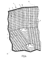
- FIG. 1 is a top view of a sector and connecting elements of a tank according to one embodiment of the invention
- FIG. 2 is a top view of a connecting element of the tank of FIG. 1 ,
- FIG. 3 is a top view of a rectangular element of the tank of FIG. 1 ,
- FIG. 4 is a perspective view of the connecting element of FIG. 2 .
- FIG. 5 is a partial top view of the bottom wall of a tank according to another embodiment of the invention.
- FIGS. 6 and 7 are partial perspective views of the tank of FIG. 1 , with connecting elements according to a first variation of embodiment
- FIG. 8 illustrates two connecting elements according to a second variation of the invention
- FIG. 9 is a schematic of a rectilinear corner bead connecting a bottom wall to a vertical wall.
- FIGS. 6 and 7 we have illustrated the tight membrane of a ground tank 1 for the storage of liquefied natural gas (LNG).
- the tank 1 also comprises a concrete support structure, which is not illustrated, and a thermally insulating barrier 15 , which is schematically illustrated, located between the tight membrane and the support structure.
- the tight membrane of the tank 1 is a cylindrical structure which comprises a bottom wall 2 and a vertical wall 3 .
- the bottom wall 2 has the shape of a regular polygon, with twenty sides 6 in the example shown in FIGS. 6 and 7 .
- the invention concerns other types of polygons, in particular with five sides or more.
- the bottom wall 2 has a plurality of sectors 4 each corresponding to a side 6 .
- the sectors 4 are rotated images of each other.
- the vertical wall 2 is made up of a plurality of vertical faces 5 each corresponding to a side 6 .
- the bottom wall 2 and the vertical wall 3 are made up of a plurality of metallic panels connected to each other by welding, and which have ripples allowing the contraction of the panels during temperature variations. Fixing and welding of the panels as well as the formation of the ripples can be done according to techniques known in the field of LNG storage or transport tanks.
- the metallic panels comprise rectangular panels 8 having a length L and width 1 , shown in FIG. 3 , as well as connecting panels 9 in a symmetrical quadrilateral shape, having two sides with a length L and two sides with a length 1 / 2 , shown in FIG. 2 .
- FIG. 1 shows how the rectangular panels 8 are arranged to cover a sector 4 of the bottom wall 2 .
- a plurality of rectangular panels 8 are arranged according to three rows, with the width parallel to the side 6 . From one row to the next, the rectangular panels 8 are arranged in staggered rows and each time there is one less panel 8 as one approaches the center.
- the space left free between a panel 8 located at the end of a row of a first sector and the panel 8 located at the end of a corresponding row of a second adjacent center always has an identical symmetrical quadrilateral shape. All these spaces with identical shapes can therefore be occupied by a plurality of connecting panels 9 .
- the bottom wall 2 can be entirely formed with a plurality of identical rectangular panels 8 , a plurality of identical connecting panels 9 , and a central piece 13 , which can potentially be formed by connecting panels 9 as shown in FIG. 7 .
- the bottom wall 2 is therefore made up of two or, at most, three different types of panels.
- the small side of the outermost rectangular panels 8 is not mixed with the side 6 , but is a small distance away from it, for example 10 cm.
- a rectilinear corner bead with an L-shaped section is arranged along the side 6 .
- the corner bead comprises a horizontal board to which the most off center rectangular panels 8 are connected, by their width.
- the corner bead also comprises a vertical board to which the panels of the vertical wall are connected.
- the corner bead is only one example of connection between the bottom wall 2 and the vertical wall 3 .
- This connection can be realized according to other techniques, for example similarly to the connection rings used in the field of LNG transport tanks. Regardless of the technique chosen, as it involves making a connection between two perpendicular walls made up primarily of rectangular panels whereof the edges are parallel and perpendicular to the intersection edge, this connection is relatively simple and requires only a limited number of pieces.
- the vertical wall 3 is made up of rectangular metallic panels. In one embodiment, these are the same rectangular panels 8 as those of the bottom wall 2 , which makes it possible to limit the number of types of panels needed.
- the longitudinal ripples 7 of the bottom wall 2 can be connected to the corresponding longitudinal ripples 7 of the vertical wall 3 , which makes it possible to limit the constraints due to thermal contraction.
- the panels have ripples allowing them to contract when temperature variations take place.
- the rectangular panels 8 have two longitudinal ripples 7 and a plurality of transverse ripples 10 .
- the ripples 7 and 10 of the rectangular panels 8 are connected to each other.
- the connecting panels 9 also have ripples connected to the ripples of the adjacent rectangular panels 8 .
- the connecting panel 9 comprises terminal ripples 11 connected to longitudinal ripples 7 , and connecting ripples 12 connected to the transverse ripples 10 of the adjacent rectangular panels 8 .
- Other arrangements of the ripples on the connecting panels 9 are possible, and one example is illustrated in FIG. 6 .
- FIG. 5 illustrates a different arrangement of the panels of the bottom wall 2 .
- rectangular panels 8 ′ instead of using rectangular panels 8 which all have the same length L corresponding to the length of one side of the connecting panels 9 , one can use rectangular panels 8 ′ of different lengths, which for example extend from the side 6 of the bottom wall to a small edge of a connecting panel.
- These rectangular panels 8 ′ can for example be strakes with raised edges, the production of which and fixing on welding media are known in the field of LNG storage or transport tanks. Such strakes can be produced in a material with a small coefficient of expansion, for example in Invar, and are not provided with ripples.
- the thermally insulating barrier 15 of the tank 1 is illustrated schematically. It can be made up of a plurality of insulating panels.
- the panels of the bottom wall comprise rectangular panels and connecting panels arranged similarly to the rectangular panels 8 and the connecting panels 9 , respectively.
- connecting panels 9 in a quadrilateral shape, two panels 9 touching only at their respective peaks, as one can see in FIGS. 1 and 5 .
- the connecting panels 9 ′ have the shape of a quadrilateral with cut tops, thereby forming a hexagon, and two adjacent connecting panels 9 ′ are in contact on two sides.
- the present invention is not limited to tanks. On the contrary, it concerns any cylindrical structure comprising a polygonal bottom wall made up of rectangular elements distributed in sectors and connecting elements between sectors.
Landscapes
- Engineering & Computer Science (AREA)
- Thermal Sciences (AREA)
- Mechanical Engineering (AREA)
- General Engineering & Computer Science (AREA)
- Physics & Mathematics (AREA)
- Filling Or Discharging Of Gas Storage Vessels (AREA)
- Prostheses (AREA)
- Superconductors And Manufacturing Methods Therefor (AREA)
- Road Signs Or Road Markings (AREA)
- Applications Or Details Of Rotary Compressors (AREA)
- Revetment (AREA)
- Packages (AREA)
- Apparatus For Radiation Diagnosis (AREA)
- Muffle Furnaces And Rotary Kilns (AREA)
- Mechanical Optical Scanning Systems (AREA)
- Lining And Supports For Tunnels (AREA)
- Finishing Walls (AREA)
- Rigid Containers With Two Or More Constituent Elements (AREA)
- Burglar Alarm Systems (AREA)
Applications Claiming Priority (3)
| Application Number | Priority Date | Filing Date | Title |
|---|---|---|---|
| FR0753220A FR2912385B1 (fr) | 2007-02-13 | 2007-02-13 | Structure cylindrique composee d'elements rectangulaires. |
| FR0753220 | 2007-02-13 | ||
| PCT/FR2008/050103 WO2008107606A2 (fr) | 2007-02-13 | 2008-01-23 | Structure cylindrique composee d'elements rectangulaires |
Publications (2)
| Publication Number | Publication Date |
|---|---|
| US20100071285A1 US20100071285A1 (en) | 2010-03-25 |
| US8550276B2 true US8550276B2 (en) | 2013-10-08 |
Family
ID=38686772
Family Applications (1)
| Application Number | Title | Priority Date | Filing Date |
|---|---|---|---|
| US12/447,534 Expired - Fee Related US8550276B2 (en) | 2007-02-13 | 2008-01-23 | Cylindrical structure made up of rectangular elements |
Country Status (32)
| Country | Link |
|---|---|
| US (1) | US8550276B2 (he) |
| EP (1) | EP2117963B8 (he) |
| JP (1) | JP5202543B2 (he) |
| KR (2) | KR20130005318A (he) |
| CN (1) | CN101611256B (he) |
| AT (1) | ATE471893T1 (he) |
| AU (1) | AU2008223676B2 (he) |
| BR (1) | BRPI0806482B1 (he) |
| CA (1) | CA2665306C (he) |
| CU (1) | CU23785A3 (he) |
| CY (1) | CY1110786T1 (he) |
| DE (1) | DE602008001608D1 (he) |
| DO (1) | DOP2009000203A (he) |
| EG (1) | EG25437A (he) |
| ES (1) | ES2348004T3 (he) |
| FR (1) | FR2912385B1 (he) |
| HN (1) | HN2009001414A (he) |
| HR (1) | HRP20100523T1 (he) |
| IL (1) | IL198664A (he) |
| MA (1) | MA31191B1 (he) |
| MX (1) | MX2009006975A (he) |
| MY (1) | MY151581A (he) |
| NZ (1) | NZ575266A (he) |
| PL (1) | PL2117963T3 (he) |
| PT (1) | PT2117963E (he) |
| RU (1) | RU2430296C2 (he) |
| SA (1) | SA08290497B1 (he) |
| TN (1) | TN2009000114A1 (he) |
| TW (1) | TWI407035B (he) |
| UA (1) | UA96180C2 (he) |
| WO (1) | WO2008107606A2 (he) |
| ZA (1) | ZA200902303B (he) |
Cited By (2)
| Publication number | Priority date | Publication date | Assignee | Title |
|---|---|---|---|---|
| WO2022200539A1 (fr) | 2021-03-24 | 2022-09-29 | Gaztransport Et Technigaz | Procédé de traçage pour la construction d'une installation de stockage de gaz liquéfié comportant une structure porteuse polygonale |
| WO2024068998A1 (fr) | 2022-09-30 | 2024-04-04 | Gaztransport Et Technigaz | Procédé de contrôle de géométrie mis en œuvre par ordinateur |
Families Citing this family (12)
| Publication number | Priority date | Publication date | Assignee | Title |
|---|---|---|---|---|
| FR2951521B1 (fr) * | 2009-10-20 | 2011-11-18 | Gaztransp Et Technigaz | Cuve polygonale pour gnl |
| FR2953582B1 (fr) | 2009-12-09 | 2012-11-30 | Gaztransp Et Technigaz | Cuve pour fluide cryogenique |
| US8578670B2 (en) * | 2011-07-05 | 2013-11-12 | City University Of Hong Kong | Construction structure and method of making thereof |
| US9021755B2 (en) | 2011-07-05 | 2015-05-05 | City University Of Hong Kong | Method of making use of surface nanocrystallization for building reinforced construction structure |
| US9010047B2 (en) * | 2011-07-05 | 2015-04-21 | City University Of Hong Kong | Construction structure and method of making thereof |
| DE202014100652U1 (de) * | 2014-02-14 | 2014-03-06 | Lindner Group Kg | Auskleidung eines Lagers für kryogen verflüssigte Medien |
| KR101931879B1 (ko) * | 2017-06-28 | 2019-03-13 | 가즈트랑스포르 에 떼끄니가즈 | 밀봉된 멤브레인 및 밀봉된 멤브레인을 조립하기 위한 방법 |
| CN115992929B (zh) * | 2023-03-16 | 2023-06-13 | 中太海事技术(上海)有限公司 | 一种液化气体的储存容器 |
| FR3154785B1 (fr) | 2023-10-27 | 2025-10-03 | Gaztransport Et Technigaz | Installation de stockage de gaz liquéfié comportant une structure porteuse polygonale |
| FR3154784A1 (fr) | 2023-10-27 | 2025-05-02 | Gaztransport Et Technigaz | Installation de stockage de gaz liquéfié comportant une structure porteuse polygonale |
| WO2025155141A1 (ko) * | 2024-01-19 | 2025-07-24 | 에이치디현대중공업 주식회사 | 액화가스 저장탱크 |
| CN117847403B (zh) * | 2024-03-06 | 2024-06-11 | 沪东中华造船(集团)有限公司 | 一种陆用薄膜型储罐 |
Citations (18)
| Publication number | Priority date | Publication date | Assignee | Title |
|---|---|---|---|---|
| US1599110A (en) * | 1925-07-15 | 1926-09-07 | Manville Johns Inc | Vapor seal for tanks and method of making the same |
| US2126996A (en) * | 1934-03-30 | 1938-08-16 | Andrew A Kramer | Storage tank |
| US2237308A (en) * | 1939-02-17 | 1941-04-08 | Chicago Bridge & Iron Co | Container |
| US2499054A (en) * | 1950-02-28 | Liquid treatment apparatus | ||
| US2748904A (en) * | 1951-09-25 | 1956-06-05 | Arndt Raymond | Corn crib |
| US3225955A (en) * | 1961-01-16 | 1965-12-28 | Hydrocarbon Research Inc | Land storage for liquefied gases |
| FR1457617A (fr) | 1965-09-22 | 1966-01-24 | Technigaz | Réservoir fixe étanche ou analogue et son procédé de construction |
| US3277620A (en) * | 1965-04-12 | 1966-10-11 | Elmer W Martin | Demountable building |
| FR1546524A (fr) | 1967-06-21 | 1968-11-22 | Gaz De France | Réservoir de stockage pour gaz liquéfié à basse température |
| US3979871A (en) * | 1974-12-05 | 1976-09-14 | Pollock Eugene B | Modular floor structure |
| FR2398961A1 (fr) | 1977-07-26 | 1979-02-23 | Gaz Transport | Cuve thermiquement isolante pour le stockage terrestre d'un liquide a basse temperature, en particulier de gaz naturels liquefies |
| US4756163A (en) | 1986-09-25 | 1988-07-12 | Tejendra Garg | Containers for storing and/or transporting fluids |
| US4760932A (en) * | 1987-08-28 | 1988-08-02 | The United States Of America As Represented By The Secretary Of The Army | Segmented, collapsible, rigid liquid storage tank |
| FR2739675A1 (fr) | 1995-10-05 | 1997-04-11 | Gaztransport Et Technigaz | Cuve terrestre pour le stockage du liquide a basse temperature |
| WO2000021847A1 (en) | 1998-10-15 | 2000-04-20 | Mobil Oil Corporation | Liquefied gas storage tank |
| US6638348B2 (en) | 2001-01-26 | 2003-10-28 | Honda Giken Kogyo Kabushiki Kaisha | Metal hydride tank apparatus |
| US20040118844A1 (en) * | 2002-12-09 | 2004-06-24 | Bennett Paul D. | Fluid storage tank |
| FR2877693A1 (fr) | 2004-11-08 | 2006-05-12 | Peugeot Citroen Automobiles Sa | SYSTEME DE TRAITEMENT DES NOx DE GAZ D'ECHAPPEMENT D'UN MOTEUR THERMIQUE DE VEHICULE AUTOMOBILE |
Family Cites Families (3)
| Publication number | Priority date | Publication date | Assignee | Title |
|---|---|---|---|---|
| JPS503291Y1 (he) * | 1972-10-04 | 1975-01-28 | ||
| JP2001058693A (ja) * | 1999-08-24 | 2001-03-06 | Kawasaki Heavy Ind Ltd | 旋回挙動型メンブレン構造の方形タンク |
| FR2877639B1 (fr) * | 2004-11-10 | 2006-12-15 | Gaz Transp Et Technigaz Soc Pa | Cuve etanche et thermiquement isolee integree a la stucture porteuse d'un navire |
-
2007
- 2007-02-13 FR FR0753220A patent/FR2912385B1/fr not_active Expired - Fee Related
-
2008
- 2008-01-23 NZ NZ575266A patent/NZ575266A/en not_active IP Right Cessation
- 2008-01-23 WO PCT/FR2008/050103 patent/WO2008107606A2/fr not_active Ceased
- 2008-01-23 EP EP08761970A patent/EP2117963B8/fr active Active
- 2008-01-23 MY MYPI20093341 patent/MY151581A/en unknown
- 2008-01-23 KR KR1020127033739A patent/KR20130005318A/ko not_active Withdrawn
- 2008-01-23 DE DE602008001608T patent/DE602008001608D1/de active Active
- 2008-01-23 CA CA2665306A patent/CA2665306C/fr active Active
- 2008-01-23 AT AT08761970T patent/ATE471893T1/de not_active IP Right Cessation
- 2008-01-23 HR HR20100523T patent/HRP20100523T1/hr unknown
- 2008-01-23 ZA ZA200902303A patent/ZA200902303B/xx unknown
- 2008-01-23 CN CN2008800009437A patent/CN101611256B/zh active Active
- 2008-01-23 CU CU20090054A patent/CU23785A3/es not_active IP Right Cessation
- 2008-01-23 BR BRPI0806482-2A patent/BRPI0806482B1/pt not_active IP Right Cessation
- 2008-01-23 US US12/447,534 patent/US8550276B2/en not_active Expired - Fee Related
- 2008-01-23 RU RU2009109365/06A patent/RU2430296C2/ru active
- 2008-01-23 PT PT08761970T patent/PT2117963E/pt unknown
- 2008-01-23 UA UAA200908858A patent/UA96180C2/ru unknown
- 2008-01-23 AU AU2008223676A patent/AU2008223676B2/en not_active Ceased
- 2008-01-23 JP JP2009548719A patent/JP5202543B2/ja not_active Expired - Fee Related
- 2008-01-23 ES ES08761970T patent/ES2348004T3/es active Active
- 2008-01-23 KR KR1020097016318A patent/KR20090115718A/ko not_active Ceased
- 2008-01-23 MX MX2009006975A patent/MX2009006975A/es active IP Right Grant
- 2008-01-23 PL PL08761970T patent/PL2117963T3/pl unknown
- 2008-08-01 TW TW097129445A patent/TWI407035B/zh not_active IP Right Cessation
- 2008-08-12 SA SA8290497A patent/SA08290497B1/ar unknown
-
2009
- 2009-03-31 TN TN2009000114A patent/TN2009000114A1/fr unknown
- 2009-05-10 IL IL198664A patent/IL198664A/he not_active IP Right Cessation
- 2009-07-28 HN HN2009001414A patent/HN2009001414A/es unknown
- 2009-08-11 DO DO2009000203A patent/DOP2009000203A/es unknown
- 2009-08-12 EG EG2009081229A patent/EG25437A/xx active
- 2009-08-13 MA MA32176A patent/MA31191B1/fr unknown
-
2010
- 2010-09-23 CY CY20101100854T patent/CY1110786T1/el unknown
Patent Citations (20)
| Publication number | Priority date | Publication date | Assignee | Title |
|---|---|---|---|---|
| US2499054A (en) * | 1950-02-28 | Liquid treatment apparatus | ||
| US1599110A (en) * | 1925-07-15 | 1926-09-07 | Manville Johns Inc | Vapor seal for tanks and method of making the same |
| US2126996A (en) * | 1934-03-30 | 1938-08-16 | Andrew A Kramer | Storage tank |
| US2237308A (en) * | 1939-02-17 | 1941-04-08 | Chicago Bridge & Iron Co | Container |
| US2748904A (en) * | 1951-09-25 | 1956-06-05 | Arndt Raymond | Corn crib |
| US3225955A (en) * | 1961-01-16 | 1965-12-28 | Hydrocarbon Research Inc | Land storage for liquefied gases |
| US3277620A (en) * | 1965-04-12 | 1966-10-11 | Elmer W Martin | Demountable building |
| FR1457617A (fr) | 1965-09-22 | 1966-01-24 | Technigaz | Réservoir fixe étanche ou analogue et son procédé de construction |
| US3511003A (en) | 1965-09-22 | 1970-05-12 | Technigaz | Fixed fluid-tight tank or the like and method of constructing same |
| FR1546524A (fr) | 1967-06-21 | 1968-11-22 | Gaz De France | Réservoir de stockage pour gaz liquéfié à basse température |
| US3979871A (en) * | 1974-12-05 | 1976-09-14 | Pollock Eugene B | Modular floor structure |
| FR2398961A1 (fr) | 1977-07-26 | 1979-02-23 | Gaz Transport | Cuve thermiquement isolante pour le stockage terrestre d'un liquide a basse temperature, en particulier de gaz naturels liquefies |
| US4225054A (en) | 1977-07-26 | 1980-09-30 | Gaz-Transport | Thermally insulated tank for land storage of low temperature liquids |
| US4756163A (en) | 1986-09-25 | 1988-07-12 | Tejendra Garg | Containers for storing and/or transporting fluids |
| US4760932A (en) * | 1987-08-28 | 1988-08-02 | The United States Of America As Represented By The Secretary Of The Army | Segmented, collapsible, rigid liquid storage tank |
| FR2739675A1 (fr) | 1995-10-05 | 1997-04-11 | Gaztransport Et Technigaz | Cuve terrestre pour le stockage du liquide a basse temperature |
| WO2000021847A1 (en) | 1998-10-15 | 2000-04-20 | Mobil Oil Corporation | Liquefied gas storage tank |
| US6638348B2 (en) | 2001-01-26 | 2003-10-28 | Honda Giken Kogyo Kabushiki Kaisha | Metal hydride tank apparatus |
| US20040118844A1 (en) * | 2002-12-09 | 2004-06-24 | Bennett Paul D. | Fluid storage tank |
| FR2877693A1 (fr) | 2004-11-08 | 2006-05-12 | Peugeot Citroen Automobiles Sa | SYSTEME DE TRAITEMENT DES NOx DE GAZ D'ECHAPPEMENT D'UN MOTEUR THERMIQUE DE VEHICULE AUTOMOBILE |
Non-Patent Citations (2)
| Title |
|---|
| International Search Report dated Sep. 12, 2008, from correspond PCT application. |
| Taiwan Search Report, dated Oct. 29, 2012, in corresponding 097129445. |
Cited By (6)
| Publication number | Priority date | Publication date | Assignee | Title |
|---|---|---|---|---|
| WO2022200539A1 (fr) | 2021-03-24 | 2022-09-29 | Gaztransport Et Technigaz | Procédé de traçage pour la construction d'une installation de stockage de gaz liquéfié comportant une structure porteuse polygonale |
| WO2022200536A1 (fr) | 2021-03-24 | 2022-09-29 | Gaztransport Et Technigaz | Installation de stockage de gaz liquéfié comportant une structure porteuse polygonale |
| FR3121196A1 (fr) | 2021-03-24 | 2022-09-30 | Gaztransport Et Technigaz | Installation de stockage de gaz liquéfié comportant une structure porteuse polygonale, et procédé de traçage pour la construction de cette installation |
| US12460772B2 (en) | 2021-03-24 | 2025-11-04 | Gaztransport Et Technigaz | Liquefied gas storage facility having a polygonal load-bearing structure |
| WO2024068998A1 (fr) | 2022-09-30 | 2024-04-04 | Gaztransport Et Technigaz | Procédé de contrôle de géométrie mis en œuvre par ordinateur |
| FR3140434A1 (fr) | 2022-09-30 | 2024-04-05 | Gaztransport Et Technigaz | Procédé de contrôle de géométrie mis en œuvre par ordinateur |
Also Published As
Similar Documents
| Publication | Publication Date | Title |
|---|---|---|
| US8550276B2 (en) | Cylindrical structure made up of rectangular elements | |
| US8813983B2 (en) | Fluidtight tank | |
| KR101325689B1 (ko) | 액화 천연 가스 저장 탱크 | |
| KR101455637B1 (ko) | 액화천연가스 저장탱크의 단열구조 | |
| KR20240033384A (ko) | 액화가스 단열시스템의 코너부 구조 | |
| KR20150100010A (ko) | 2차 방벽과 이를 가지는 lng 저장탱크 및 2차 방벽 제조방법 | |
| KR20120084972A (ko) | 유체 저장 탱크용 금속 멤브레인 패널 | |
| KR20160052117A (ko) | 액화천연가스 저장탱크의 단열패널 | |
| KR102020965B1 (ko) | 멤브레인 접합구조 및 상기 멤브레인 접합구조를 포함하는 액화가스 저장탱크 | |
| KR102657770B1 (ko) | 상하부 단열벽이 교차 배치되는 lng 저장탱크의 단열시스템 | |
| HK1140001B (en) | Cylindrical structure composed of rectangular elements | |
| KR102712754B1 (ko) | 액화천연가스 저장탱크의 단열패널 배치구조 | |
| KR102662431B1 (ko) | 액화천연가스 저장탱크 | |
| JP2015190484A (ja) | 液化ガスタンクの球状曲面被覆用断熱パネル | |
| KR102075970B1 (ko) | 주름 집중형 멤브레인 및 이를 이용한 극저온 유체 저장탱크 | |
| KR20250114231A (ko) | 액화가스 저장탱크 | |
| KR20190138622A (ko) | 액화천연가스 화물창 단열 시스템 | |
| KR20200042735A (ko) | 액화천연가스 운반선 |
Legal Events
| Date | Code | Title | Description |
|---|---|---|---|
| AS | Assignment |
Owner name: GAZTRANSPORT ET TECHNIGAZ,FRANCE Free format text: ASSIGNMENT OF ASSIGNORS INTEREST;ASSIGNORS:RICHARD, YVES;EZZARHOUNI, ADNAN;REEL/FRAME:022627/0478 Effective date: 20090410 Owner name: GAZTRANSPORT ET TECHNIGAZ, FRANCE Free format text: ASSIGNMENT OF ASSIGNORS INTEREST;ASSIGNORS:RICHARD, YVES;EZZARHOUNI, ADNAN;REEL/FRAME:022627/0478 Effective date: 20090410 |
|
| STCF | Information on status: patent grant |
Free format text: PATENTED CASE |
|
| CC | Certificate of correction | ||
| FPAY | Fee payment |
Year of fee payment: 4 |
|
| MAFP | Maintenance fee payment |
Free format text: PAYMENT OF MAINTENANCE FEE, 8TH YEAR, LARGE ENTITY (ORIGINAL EVENT CODE: M1552); ENTITY STATUS OF PATENT OWNER: LARGE ENTITY Year of fee payment: 8 |
|
| FEPP | Fee payment procedure |
Free format text: MAINTENANCE FEE REMINDER MAILED (ORIGINAL EVENT CODE: REM.); ENTITY STATUS OF PATENT OWNER: LARGE ENTITY |
|
| LAPS | Lapse for failure to pay maintenance fees |
Free format text: PATENT EXPIRED FOR FAILURE TO PAY MAINTENANCE FEES (ORIGINAL EVENT CODE: EXP.); ENTITY STATUS OF PATENT OWNER: LARGE ENTITY |
|
| STCH | Information on status: patent discontinuation |
Free format text: PATENT EXPIRED DUE TO NONPAYMENT OF MAINTENANCE FEES UNDER 37 CFR 1.362 |
|
| FP | Lapsed due to failure to pay maintenance fee |
Effective date: 20251008 |