US8516753B2 - Fork configuration dampers and method of using same - Google Patents
Fork configuration dampers and method of using same Download PDFInfo
- Publication number
- US8516753B2 US8516753B2 US13/166,453 US201113166453A US8516753B2 US 8516753 B2 US8516753 B2 US 8516753B2 US 201113166453 A US201113166453 A US 201113166453A US 8516753 B2 US8516753 B2 US 8516753B2
- Authority
- US
- United States
- Prior art keywords
- plates
- vertically extending
- extending structural
- structural element
- overlapping region
- Prior art date
- Legal status (The legal status is an assumption and is not a legal conclusion. Google has not performed a legal analysis and makes no representation as to the accuracy of the status listed.)
- Active - Reinstated
Links
Images


Classifications
-
- E—FIXED CONSTRUCTIONS
- E04—BUILDING
- E04H—BUILDINGS OR LIKE STRUCTURES FOR PARTICULAR PURPOSES; SWIMMING OR SPLASH BATHS OR POOLS; MASTS; FENCING; TENTS OR CANOPIES, IN GENERAL
- E04H9/00—Buildings, groups of buildings or shelters adapted to withstand or provide protection against abnormal external influences, e.g. war-like action, earthquake or extreme climate
- E04H9/02—Buildings, groups of buildings or shelters adapted to withstand or provide protection against abnormal external influences, e.g. war-like action, earthquake or extreme climate withstanding earthquake or sinking of ground
- E04H9/021—Bearing, supporting or connecting constructions specially adapted for such buildings
- E04H9/022—Bearing, supporting or connecting constructions specially adapted for such buildings and comprising laminated structures of alternating elastomeric and rigid layers
-
- E—FIXED CONSTRUCTIONS
- E04—BUILDING
- E04B—GENERAL BUILDING CONSTRUCTIONS; WALLS, e.g. PARTITIONS; ROOFS; FLOORS; CEILINGS; INSULATION OR OTHER PROTECTION OF BUILDINGS
- E04B1/00—Constructions in general; Structures which are not restricted either to walls, e.g. partitions, or floors or ceilings or roofs
- E04B1/62—Insulation or other protection; Elements or use of specified material therefor
- E04B1/92—Protection against other undesired influences or dangers
- E04B1/98—Protection against other undesired influences or dangers against vibrations or shocks; against mechanical destruction, e.g. by air-raids
-
- E—FIXED CONSTRUCTIONS
- E04—BUILDING
- E04H—BUILDINGS OR LIKE STRUCTURES FOR PARTICULAR PURPOSES; SWIMMING OR SPLASH BATHS OR POOLS; MASTS; FENCING; TENTS OR CANOPIES, IN GENERAL
- E04H9/00—Buildings, groups of buildings or shelters adapted to withstand or provide protection against abnormal external influences, e.g. war-like action, earthquake or extreme climate
- E04H9/02—Buildings, groups of buildings or shelters adapted to withstand or provide protection against abnormal external influences, e.g. war-like action, earthquake or extreme climate withstanding earthquake or sinking of ground
- E04H9/021—Bearing, supporting or connecting constructions specially adapted for such buildings
- E04H9/0237—Structural braces with damping devices
-
- F—MECHANICAL ENGINEERING; LIGHTING; HEATING; WEAPONS; BLASTING
- F16—ENGINEERING ELEMENTS AND UNITS; GENERAL MEASURES FOR PRODUCING AND MAINTAINING EFFECTIVE FUNCTIONING OF MACHINES OR INSTALLATIONS; THERMAL INSULATION IN GENERAL
- F16F—SPRINGS; SHOCK-ABSORBERS; MEANS FOR DAMPING VIBRATION
- F16F1/00—Springs
- F16F1/36—Springs made of rubber or other material having high internal friction, e.g. thermoplastic elastomers
- F16F1/40—Springs made of rubber or other material having high internal friction, e.g. thermoplastic elastomers consisting of a stack of similar elements separated by non-elastic intermediate layers
-
- F—MECHANICAL ENGINEERING; LIGHTING; HEATING; WEAPONS; BLASTING
- F16—ENGINEERING ELEMENTS AND UNITS; GENERAL MEASURES FOR PRODUCING AND MAINTAINING EFFECTIVE FUNCTIONING OF MACHINES OR INSTALLATIONS; THERMAL INSULATION IN GENERAL
- F16F—SPRINGS; SHOCK-ABSORBERS; MEANS FOR DAMPING VIBRATION
- F16F1/00—Springs
- F16F1/36—Springs made of rubber or other material having high internal friction, e.g. thermoplastic elastomers
- F16F1/42—Springs made of rubber or other material having high internal friction, e.g. thermoplastic elastomers characterised by the mode of stressing
- F16F1/50—Springs made of rubber or other material having high internal friction, e.g. thermoplastic elastomers characterised by the mode of stressing loaded mainly in shear
-
- F—MECHANICAL ENGINEERING; LIGHTING; HEATING; WEAPONS; BLASTING
- F16—ENGINEERING ELEMENTS AND UNITS; GENERAL MEASURES FOR PRODUCING AND MAINTAINING EFFECTIVE FUNCTIONING OF MACHINES OR INSTALLATIONS; THERMAL INSULATION IN GENERAL
- F16F—SPRINGS; SHOCK-ABSORBERS; MEANS FOR DAMPING VIBRATION
- F16F15/00—Suppression of vibrations in systems; Means or arrangements for avoiding or reducing out-of-balance forces, e.g. due to motion
- F16F15/02—Suppression of vibrations of non-rotating, e.g. reciprocating systems; Suppression of vibrations of rotating systems by use of members not moving with the rotating systems
-
- F—MECHANICAL ENGINEERING; LIGHTING; HEATING; WEAPONS; BLASTING
- F16—ENGINEERING ELEMENTS AND UNITS; GENERAL MEASURES FOR PRODUCING AND MAINTAINING EFFECTIVE FUNCTIONING OF MACHINES OR INSTALLATIONS; THERMAL INSULATION IN GENERAL
- F16F—SPRINGS; SHOCK-ABSORBERS; MEANS FOR DAMPING VIBRATION
- F16F2230/00—Purpose; Design features
- F16F2230/0023—Purpose; Design features protective
-
- F—MECHANICAL ENGINEERING; LIGHTING; HEATING; WEAPONS; BLASTING
- F16—ENGINEERING ELEMENTS AND UNITS; GENERAL MEASURES FOR PRODUCING AND MAINTAINING EFFECTIVE FUNCTIONING OF MACHINES OR INSTALLATIONS; THERMAL INSULATION IN GENERAL
- F16F—SPRINGS; SHOCK-ABSORBERS; MEANS FOR DAMPING VIBRATION
- F16F2238/00—Type of springs or dampers
- F16F2238/04—Damper
Definitions
- the present invention relates to the field of damping systems for buildings, bridges and other structures.
- it relates to a new configuration damper, for interconnecting two elements of a structure that undergo relative movements and deformations, that increases the level of damping when the overall structure is subjected to a loading condition.
- the new configuration damper aids in controlling displacements, forces, velocities and accelerations under dynamic loading in structural systems.
- Modern buildings using typical construction components such as reinforced concrete shear walls, structural steel braced frames, structural steel or reinforced concrete moment frames or combinations thereof, have low inherent damping properties. Due to this low inherent damping, high-rise buildings, in particular, tend to be susceptible to excessive vibrations caused by dynamic loads. Excessive accelerations and torsional velocities can cause occupant discomfort, while excessive displacements can cause damage to non-structural and structural elements. For this reason it is advantageous to provide additional sources of damping to control these excessive vibrations and reduce the overall building response to dynamic loads.
- Passive supplemental dampers such as hysteretic, viscous and visco-elastic dampers are currently used in typical braced configurations and are activated under axial deformations. While this may be effective in adding damping to some structural configurations, where under this typical braced configuration the brace elements undergo significant axial deformations, they are less effective for other structural systems, such as high rise buildings where the primary mode of lateral deformation does not cause sufficient axial deformation in typical bracing elements to actuate such dampers. In order to increase the deformations to an extent sufficient to activate the dampers, special configurations using toggle bracers or scissor braces to amplify the displacements are used.
- Vibration absorbers such as Tuned Mass Dampers (TMD) and Tuned Liquid Dampers (TLD) are also used to reduce the deflections, forces, velocities and accelerations of such structures. They typically consist of a mechanical vibrating system installed on the top floor of buildings in order to maximize their effectiveness. This has the disadvantage of using up some of the most valuable real estate within the building in addition to being expensive to design and to build. They also act in a limited frequency range.
- Active systems require an external power source, an actuating force and extensive hardware and software control systems. As a result, they are expensive to design and implement, and are susceptible to power outages or failure of the control system.
- the damping system provides additional damping to a structure.
- a damping system including a first set of plates having one end thereof attached to a first vertically extending structural element, a second set of plates having one end thereof attached to a second vertically extending structural element spaced in a horizontal direction from the first vertically extending structural element.
- the first set of plates preferably includes a second end portion extending towards and overlapping with a second end portion of the second set of plates at an overlapping region.
- an energy dissipating material in the overlapping region for connecting the first set of plates and the second set of plates.
- the overlapping region is spaced from at least one or both of the first vertically extending structural element and the second vertically extending structural element.
- the overlapping region is distally spaced from the one end thereof of the first set of plates and the overlapping region is distally spaced from the one end thereof of the second set of plates.
- a structure having a first vertically extending structural element adapted to resist lateral loads applied to the structure, a second vertically extending structural element adapted to resist lateral loads applied to the structure, a coupling member adjoining the first and second vertically extending structural elements.
- the coupling member preferably includes a first set of plates having one end thereof attached to the first vertically extending structural element, a second set of plates having one end thereof attached to the second vertically extending structural element, wherein the first set of plates has a second end portion extending towards and overlapping with a second end portion of the second set of plates at an overlapping region, and further including and an energy dissipating material in the overlapping region for connecting the first set of plates and the second set of plates.
- the coupling member provides damping for vibrations occurring in the structure due to relative movement between the first and second structural elements as the energy dissipating material damps against shearing displacement between the first set of plates and the second set of plates.
- a coupling member in a building structure wherein the building structure includes first and second vertically extending structural elements adapted to resist lateral loads applied to the building structure.
- the coupling member connects the first and second vertically extending structural elements and includes a first set of plates having one end thereof attached to the first vertically extending structural element, a second set of plates having one end thereof attached to the second vertically extending structural element and arranged such that the first set of plates has a second end portion extending towards and overlapping with a second end portion of the second set of plates at an overlapping region, and also including an energy dissipating material provided in the overlapping region for connecting the first set of plates and the second set of plates.
- a damping system including a first set of plates having one end thereof attached to a first rigid extension element, the first rigid extension element connected to a first vertically extending structural element and a second set of plates having one end thereof attached to a second rigid extension element, the second rigid extension element connected to a second vertically extending structural element spaced in a horizontal direction from the first vertically extending structural element.
- the first set of plates preferably includes a second end portion extending towards and overlapping with a second end portion of the second set of plates at an overlapping region and an energy dissipating material is provided in the overlapping region for connecting the first set of plates and the second set of plates.
- FIG. 1A is a side view of coupled shear wall in a typical building
- FIG. 1B is a side view of a structural steel braced frame in a typical building
- FIG. 1C is a side view of a structural steel or reinforced concrete moment frame in a typical building
- FIG. 1D is a side view of a combination of lateral load resisting systems, a structural steel braced frame and reinforced concrete shear wall in a typical building;
- FIG. 1E is a side view of a combination of an outer structural column coupled to an inner shear wall in a typical building;
- FIG. 2A is a side view of two shear walls in a high-rise building with the disclosed invention present coupled between walls;
- FIG. 2B is a side view of a structural steel braced frame in a high-rise building with the disclosed invention present coupled between braced frames;
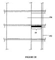
- FIG. 2C is a side view of a structural steel or reinforced concrete moment frame in a high-rise building with an embodiment of the disclosed invention present coupled between moment resisting frames;
- FIG. 2D is a side view of a combination of lateral load resisting systems, a structural steel braced frame coupled to a reinforced concrete shear wall in a highrise building with an embodiment of the disclosed invention present coupled between the steel brace frame and the concrete shear wall;
- FIG. 2E is a side view of a combination of an outer structural column coupled to an inner shear wall in a typical building with an embodiment of the disclosed invention present coupled between the column and the shear wall;
- FIG. 3 is a series of views (orthogonal, fragmentary, plan and side elevation) of a configuration of the invention comprising four steel plates coupled to five steel plates and four layers of high damping material sandwiched there between;
- FIG. 4 is a pair of views (orthogonal and plan) of an alternative configuration of the energy dissipating material with a proposed anchor system and an example of the coupling zone configuration, with the damper coupled between two shear walls;
- FIG. 5 is a pair of views (orthogonal and plan) an embodiment of the invention in which optional extension members are used to configure the damper system to be coupled between two shear walls;
- FIG. 6A is an orthogonal view of two shear walls undergoing deformation with the disclosed invention present coupled between the walls;
- FIG. 6B is a close-up of the circled area B of FIG. 6A ;
- FIG. 6C is a close-up of the circled area C of FIG. 6A .
- FIGS. 1A-1E examples of the present state of the art for the construction of mid and high-rise buildings is shown, namely using coupled reinforced concrete shear walls 114 ( FIG. 1A ), structural steel braced frames 120 ( FIG. 1B ), structural steel or reinforced concrete moment frames 130 ( FIG. 1C ), combinations thereof 140 ( FIG. 1D ), and construction with outer columns 152 (concrete or steel or any other material as used in the field of construction) and internal shear walls 156 ( FIG. 1E ).
- the coupling beams 116 , 128 , 134 , 144 , 154
- lateral braces 126 , 148
- a structure 110 using reinforced concrete shear walls 114 has concrete coupling beams 116 located in the openings 112 between the shear walls 114 .
- a structure 120 using steel columns 124 and braces 126 as shown in FIG. 1B has steel coupling beams 128 located in the openings 122 between the columns 124 .
- An alternative steel structure 130 consisting only of columns 132 and coupling beams 134 in the openings 136 is shown in FIG. 1C .
- the structure shown in FIG. 1D is a combination structure 140 , with concrete shear walls 142 and steel columns 150 and braces 148 separated by an opening 146 and joined by coupling beams 144 .
- the final structure 150 shown in FIG. 1E has external columns 152 , preferably of concrete or steel, coupled to internal shear walls 156 by coupling beams 154 .
- the damping system or damper of an embodiment of the invention replaces one or more of the coupling beams ( 116 , 128 , 134 , 144 , 154 ) or lateral bracing elements ( 126 , 148 ) of the structures shown in FIGS. 1A-1E .
- the damper 10 merely replaces the coupling beams or lateral bracing and fits within the area otherwise occupied by the coupling beams or lateral bracing.
- a damper 10 of larger depth, up to the height of an entire story can be used to replace the coupling beam, if required. In doing so, when the building is subject to dynamic wind or seismic loads, the damper 10 is deformed and provides supplemental damping to the system.
- the damping system 10 is comprised of a first set of steel plates 310 interdigitated with a second set of one or more similar steel plates 312 and coupled thereto by way of interposed layers of energy dissipating material 320 firmly adhered thereto by layers of adhesive or other bonding means.
- the ends of the two sets of plates opposite the coupled ends are structurally engaged with a pair of adjacent lateral load resisting elements 330 i.e. concrete shear walls, by embedding the ends therein or by bolting the ends to the walls in secure fashion.
- FIG. 3 discloses an example of a configuration of the damping system comprising four plates 310 connected to five plates 312 .
- the four plates 310 are coupled to the five plates 312 by way of disks of energy dissipating material 320 .
- the energy dissipating material 320 used is a high damping rubber or a high damping visco-elastic material or any other material capable of dissipating energy (either displacement dependent, or velocity dependent).
- FIG. 4 discloses another example of a damping system 10 according to the invention and comprising a first set of four plates 410 connected as in FIG. 3 to a second set of five plates 412 by larger, rectangular shaped sections of energy dissipating material 420 . Variations in the number of plates used, and the length, width, thickness and shape of the energy dissipating material can be used to tune the damping system to the particular application to maximize its damping effect. Furthermore, FIG. 4 discloses an anchorage system 414 at one end of the plates 412 for anchoring the damping system 10 to the lateral load resisting elements 430 .
- FIG. 5 discloses a configuration of the damping system 10 where the energy dissipating portion of the damper 510 is separately constructed and then connected to rigid extension elements 520 , which, in turn are configured to be structurally engaged with the lateral load resisting elements 530 at a later time, for example at a construction site.
- the plates are joined together in sets for coupling to the rigid extension elements.
- FIG. 6A discloses a structure 610 undergoing lateral deformation.
- the coupling beams 616 connecting the shear walls 614 A and 614 B are deformed, as well as the damping system 10 .
- FIG. 6B shows a close-up of a coupling beam 616 under deformation.
- the deformation of coupling beam 616 is a rotational effect arising from the lateral displacement of shear walls 614 A and 614 B.
- FIG. 6C shows a close-up of a damping system 10 under deformation in the same manner. It can be seen that the rigid extension elements 630 do not deform, but instead laterally displace, and deformation is restricted to the energy dissipating elements 635 (shown shaded). Thus, minimal rotational deformation takes place.
- Preferred embodiments of the invention thus utilize the in-plane relative deformations, in both orthogonal directions, and in-place differential rotations, between two or more lateral load resisting structural elements, regardless of composition, to provide additional damping.
- the preferred embodiments further provide a damping system capable of being installed without significant changes to the architectural and structural configuration of the building structure in which it is to be installed, and one that is easily constructed and provides a simple replacement for conventional damping systems.
- the energy dissipating material can be chosen from a wide variety of materials, such as natural or synthetic rubber (SBR, polybutadiene, polyisoprene, butyl, etc.), a choice which is within the skill of the art. It is intended the scope of the invention be limited not by this description but by the claims that follow.
- SBR natural or synthetic rubber
Landscapes
- Engineering & Computer Science (AREA)
- Architecture (AREA)
- Environmental & Geological Engineering (AREA)
- General Engineering & Computer Science (AREA)
- Business, Economics & Management (AREA)
- Emergency Management (AREA)
- Civil Engineering (AREA)
- Structural Engineering (AREA)
- Mechanical Engineering (AREA)
- Physics & Mathematics (AREA)
- Acoustics & Sound (AREA)
- Aviation & Aerospace Engineering (AREA)
- Health & Medical Sciences (AREA)
- Child & Adolescent Psychology (AREA)
- Electromagnetism (AREA)
- Buildings Adapted To Withstand Abnormal External Influences (AREA)
- Vibration Prevention Devices (AREA)
- Vibration Dampers (AREA)
Abstract
Description
Claims (16)
Priority Applications (1)
| Application Number | Priority Date | Filing Date | Title |
|---|---|---|---|
| US13/166,453 US8516753B2 (en) | 2005-10-26 | 2011-06-22 | Fork configuration dampers and method of using same |
Applications Claiming Priority (5)
| Application Number | Priority Date | Filing Date | Title |
|---|---|---|---|
| CA002524547A CA2524547A1 (en) | 2005-10-26 | 2005-10-26 | Fork configuration dampers and method of using same |
| CA2524547 | 2005-10-26 | ||
| PCT/CA2006/000985 WO2007048217A1 (en) | 2005-10-26 | 2006-06-16 | Fork configuration dampers and method of using same |
| US9150608A | 2008-04-25 | 2008-04-25 | |
| US13/166,453 US8516753B2 (en) | 2005-10-26 | 2011-06-22 | Fork configuration dampers and method of using same |
Related Parent Applications (3)
| Application Number | Title | Priority Date | Filing Date |
|---|---|---|---|
| PCT/CA2006/000985 Continuation WO2007048217A1 (en) | 2005-10-26 | 2006-06-16 | Fork configuration dampers and method of using same |
| US12/091,506 Continuation US7987639B2 (en) | 2005-10-26 | 2006-06-16 | Fork configuration dampers and method of using same |
| US9150608A Continuation | 2005-10-26 | 2008-04-25 |
Publications (2)
| Publication Number | Publication Date |
|---|---|
| US20110283653A1 US20110283653A1 (en) | 2011-11-24 |
| US8516753B2 true US8516753B2 (en) | 2013-08-27 |
Family
ID=37965150
Family Applications (2)
| Application Number | Title | Priority Date | Filing Date |
|---|---|---|---|
| US12/091,506 Active US7987639B2 (en) | 2005-10-26 | 2006-06-16 | Fork configuration dampers and method of using same |
| US13/166,453 Active - Reinstated US8516753B2 (en) | 2005-10-26 | 2011-06-22 | Fork configuration dampers and method of using same |
Family Applications Before (1)
| Application Number | Title | Priority Date | Filing Date |
|---|---|---|---|
| US12/091,506 Active US7987639B2 (en) | 2005-10-26 | 2006-06-16 | Fork configuration dampers and method of using same |
Country Status (8)
| Country | Link |
|---|---|
| US (2) | US7987639B2 (en) |
| EP (1) | EP1948878B1 (en) |
| JP (1) | JP2009513898A (en) |
| KR (1) | KR101379591B1 (en) |
| CN (1) | CN101316973B (en) |
| CA (2) | CA2524547A1 (en) |
| ES (1) | ES2558585T3 (en) |
| WO (1) | WO2007048217A1 (en) |
Cited By (5)
| Publication number | Priority date | Publication date | Assignee | Title |
|---|---|---|---|---|
| US20130283709A1 (en) * | 2011-01-14 | 2013-10-31 | Constantin Christopoulos | Coupling member for damping vibrations in building structures |
| US20170016504A1 (en) * | 2014-03-18 | 2017-01-19 | Maurer Söhne Engineering GmbH & Co. KG | Energy dissipating device |
| US11203862B2 (en) * | 2017-04-13 | 2021-12-21 | Simpson Strong-Tie Company Inc. | Member-to-member laminar fuse connection |
| US11346121B2 (en) | 2017-04-13 | 2022-05-31 | Simpson Strong-Tie Company Inc. | Member-to-member laminar fuse connection |
| US11835106B2 (en) | 2017-12-15 | 2023-12-05 | Asml Netherlands B.V. | Method for manufacturing damper device, lithographic apparatus, projection system, and device manufacturing method |
Families Citing this family (32)
| Publication number | Priority date | Publication date | Assignee | Title |
|---|---|---|---|---|
| EP2265840B1 (en) * | 2008-03-14 | 2019-05-08 | Damptech A/S | Bearing for structures |
| ES2358936B1 (en) * | 2008-04-10 | 2012-03-21 | Universitat De Girona | MODULAR POWER DISSIPATION SYSTEM. |
| CN102348859B (en) * | 2009-03-12 | 2013-12-04 | 新日铁住金株式会社 | Connecting metal appliances, vibration-damping structures, and building structures |
| JP5175250B2 (en) * | 2009-07-31 | 2013-04-03 | 株式会社神戸製鋼所 | Vibration reduction member |
| MX2012003202A (en) * | 2009-09-25 | 2012-05-29 | Vsl Int Ag | Method and structure for damping movement in buildings. |
| CN102162304B (en) * | 2011-03-09 | 2012-06-20 | 中国建筑第八工程局有限公司 | Construction method for installing viscous damper |
| US8941814B2 (en) * | 2011-06-20 | 2015-01-27 | Nikon Corporation | Multiple-blade holding devices |
| CN102322099A (en) * | 2011-06-23 | 2012-01-18 | 河南理工大学 | Structure for preventing wall bodies in mining areas from mining-induced deformation |
| WO2013010917A1 (en) * | 2011-07-15 | 2013-01-24 | Damptech A/S | Passive damper |
| US8607513B2 (en) * | 2011-12-30 | 2013-12-17 | Panelclaw, Inc. | Thermal growth compensators, systems, and methods |
| US8844205B2 (en) | 2012-01-06 | 2014-09-30 | The Penn State Research Foundation | Compressed elastomer damper for earthquake hazard reduction |
| US10655328B2 (en) * | 2012-05-24 | 2020-05-19 | The University Of Kentucky Research Foundation | Structural reinforcement, reinforced structural member and related method |
| US8827586B2 (en) * | 2012-06-27 | 2014-09-09 | The Boeing Company | Damping mechanical linkage |
| CA2924617C (en) * | 2013-10-11 | 2017-02-28 | The Governing Council Of The University Of Toronto | Viscous wall coupling damper for use in an outrigger building configuration |
| CN103924666A (en) * | 2014-04-11 | 2014-07-16 | 北京工业大学 | Self-reset pre-stressed buckling-prevention herringbone tubular veneer supporting system for industrial assembly type multi-layer and high-rise steel structures |
| RU2558818C1 (en) * | 2014-07-10 | 2015-08-10 | Олег Савельевич Кочетов | Single-use shock absorber with damaged elements |
| RU2558035C1 (en) * | 2014-07-10 | 2015-07-27 | Олег Савельевич Кочетов | Shock absorber of single action |
| CN107109841A (en) * | 2014-11-07 | 2017-08-29 | 渥太华大学 | Use the seismic hardening of traditional armored concrete moment resisting of buckling restrained brace |
| US9752645B1 (en) * | 2016-04-20 | 2017-09-05 | Hutchinson Antivibration Systems Inc. | Anti-vibration device |
| TR201607751A2 (en) | 2016-06-08 | 2017-12-21 | Ali Salem Milani | Torsional Hysteretic Dumper |
| CN106639465B (en) * | 2016-11-15 | 2018-09-28 | 东南大学 | A kind of end has the energy-dissipating type buckling induction support of four folding line type of varied angle induction unit |
| RU2642190C1 (en) * | 2017-01-13 | 2018-01-24 | Олег Савельевич Кочетов | Single action shock absorber with breakable elements |
| CN107939137A (en) * | 2017-12-27 | 2018-04-20 | 华侨大学 | A kind of marmem piezoelectric friction damper device |
| JP7042145B2 (en) * | 2018-04-05 | 2022-03-25 | 株式会社鷺宮製作所 | Test equipment using a seismic isolation damper test fixing jig and a seismic isolation damper test fixing jig |
| CN109694008B (en) * | 2019-01-02 | 2020-06-30 | 中国建筑第八工程局有限公司 | Shearing energy dissipation wall attaching rod and using method thereof |
| CN110735538B (en) * | 2019-08-20 | 2023-01-31 | 东南大学 | Assembly type reinforcing structure with external contact surface energy consumption of existing structure |
| CN110805201A (en) * | 2019-11-21 | 2020-02-18 | 大连交通大学 | Replaceable coupling beam with dual energy consumption capability |
| US11879264B2 (en) * | 2020-04-04 | 2024-01-23 | Kinetica Dynamics Inc. | Dual-phase vibration damping building coupling member with lock-up |
| CN113756458B (en) * | 2020-06-05 | 2024-03-19 | 南华大学 | A piezoelectric viscous damper |
| CN112854557A (en) * | 2021-01-07 | 2021-05-28 | 中国二十冶集团有限公司 | Shear wall device and combined shear wall system |
| CN113606283B (en) * | 2021-07-30 | 2024-04-16 | 安徽工程大学 | Intelligent automobile vibration reduction and energy recovery power generation device |
| CN113802911B (en) * | 2021-11-01 | 2022-11-18 | 西安建筑科技大学 | TMD-like structure system based on C-shaped shell shock insulation layer |
Citations (18)
| Publication number | Priority date | Publication date | Assignee | Title |
|---|---|---|---|---|
| US3605953A (en) * | 1969-05-26 | 1971-09-20 | Minnesota Mining & Mfg | Bidirectional damping unit |
| US3691712A (en) * | 1969-05-13 | 1972-09-19 | Monsanto Co | Damping system |
| US4039050A (en) * | 1969-05-13 | 1977-08-02 | Monsanto Company | Damping system |
| US4499694A (en) * | 1982-06-18 | 1985-02-19 | Development Finance Corporation Of New Zealand | Cyclic shear energy absorber |
| US4761925A (en) * | 1986-03-31 | 1988-08-09 | Bridgestone Corporation | Anti-seismic rubber bearing |
| JPH05133137A (en) * | 1991-07-24 | 1993-05-28 | Nippon Steel Corp | Vibration damping device for building |
| US5271197A (en) * | 1986-09-26 | 1993-12-21 | Shimizu Construction Co., Ltd. | Earthquake resistant multi-story building |
| US5491944A (en) * | 1991-10-26 | 1996-02-20 | Mtu Motoren- Und Turbinen-Union Friedrichshafen Gmbh | Embedded unit in a concrete foundation |
| US5842312A (en) * | 1995-03-01 | 1998-12-01 | E*Sorb Systems | Hysteretic damping apparati and methods |
| US5946866A (en) * | 1995-07-21 | 1999-09-07 | Minnesota Mining And Manufacturing Company | Modular damper |
| US6141919A (en) * | 1996-01-12 | 2000-11-07 | Robinson Seismic Limited | Energy absorber |
| US6233884B1 (en) * | 1997-10-20 | 2001-05-22 | Steven B. Tipping | Method and apparatus to control seismic forces, accelerations, and displacements of structures |
| US6457284B1 (en) * | 1998-09-02 | 2002-10-01 | Shimizu Corporation | Structure for installing a viscous vibration damping wall and method of installing the same |
| US6840017B1 (en) * | 2000-10-24 | 2005-01-11 | Oiles Corporation | Vibration control structure |
| US7076926B2 (en) * | 2001-08-07 | 2006-07-18 | Kazuhiko Kasai | Damping intermediate pillar and damping structure using the same |
| US7174680B2 (en) * | 2002-05-29 | 2007-02-13 | Sme Steel Contractors, Inc. | Bearing brace apparatus |
| US20080016794A1 (en) * | 2004-03-03 | 2008-01-24 | Robert Tremblay | Self-Centering Energy Dissipative Brace Apparatus With Tensioning Elements |
| US7712266B2 (en) * | 2007-05-22 | 2010-05-11 | Skidmore Owings & Merrill Llp | Seismic structural device |
Family Cites Families (12)
| Publication number | Priority date | Publication date | Assignee | Title |
|---|---|---|---|---|
| JP3514586B2 (en) * | 1996-06-03 | 2004-03-31 | 鹿島建設株式会社 | High rigidity damper |
| JPH10220062A (en) | 1997-02-10 | 1998-08-18 | Shimizu Corp | Vibration control structure of building structure |
| JP2966807B2 (en) * | 1997-03-21 | 1999-10-25 | 戸田建設株式会社 | Damping frame |
| JPH11153194A (en) | 1997-11-20 | 1999-06-08 | Nippon Steel Corp | Vibration damping member with integrated elasto-plastic and visco-elastic damper |
| JPH11343675A (en) * | 1998-04-01 | 1999-12-14 | Mitsubishi Heavy Ind Ltd | Damping device and damping structure |
| JP2002194917A (en) * | 2000-12-25 | 2002-07-10 | Building Research Institute | Frame earthquake resistant structure |
| JP2002235454A (en) * | 2001-02-07 | 2002-08-23 | Toyo Tire & Rubber Co Ltd | Damping damper device |
| JP2003239220A (en) * | 2002-02-18 | 2003-08-27 | Shimizu Corp | Vibration control elevated structure |
| JP2004197402A (en) * | 2002-12-18 | 2004-07-15 | Shimizu Corp | Damping structure building |
| JP4070616B2 (en) * | 2003-01-10 | 2008-04-02 | カヤバ工業株式会社 | Damping apparatus and damping method |
| KR100516332B1 (en) * | 2003-06-11 | 2005-09-23 | 재단법인 포항산업과학연구원 | Steel structure equipped with connection damper |
| JP3856783B2 (en) * | 2003-10-21 | 2006-12-13 | 等 塩原 | Seismic frame using damper integrated brace and oil damper used for it |
-
2005
- 2005-10-26 CA CA002524547A patent/CA2524547A1/en not_active Abandoned
-
2006
- 2006-06-16 WO PCT/CA2006/000985 patent/WO2007048217A1/en not_active Ceased
- 2006-06-16 KR KR1020087012596A patent/KR101379591B1/en active Active
- 2006-06-16 JP JP2008536887A patent/JP2009513898A/en active Pending
- 2006-06-16 US US12/091,506 patent/US7987639B2/en active Active
- 2006-06-16 CA CA2634641A patent/CA2634641C/en active Active
- 2006-06-16 EP EP06761059.2A patent/EP1948878B1/en active Active
- 2006-06-16 ES ES06761059.2T patent/ES2558585T3/en active Active
- 2006-06-16 CN CN200680040409XA patent/CN101316973B/en active Active
-
2011
- 2011-06-22 US US13/166,453 patent/US8516753B2/en active Active - Reinstated
Patent Citations (18)
| Publication number | Priority date | Publication date | Assignee | Title |
|---|---|---|---|---|
| US3691712A (en) * | 1969-05-13 | 1972-09-19 | Monsanto Co | Damping system |
| US4039050A (en) * | 1969-05-13 | 1977-08-02 | Monsanto Company | Damping system |
| US3605953A (en) * | 1969-05-26 | 1971-09-20 | Minnesota Mining & Mfg | Bidirectional damping unit |
| US4499694A (en) * | 1982-06-18 | 1985-02-19 | Development Finance Corporation Of New Zealand | Cyclic shear energy absorber |
| US4761925A (en) * | 1986-03-31 | 1988-08-09 | Bridgestone Corporation | Anti-seismic rubber bearing |
| US5271197A (en) * | 1986-09-26 | 1993-12-21 | Shimizu Construction Co., Ltd. | Earthquake resistant multi-story building |
| JPH05133137A (en) * | 1991-07-24 | 1993-05-28 | Nippon Steel Corp | Vibration damping device for building |
| US5491944A (en) * | 1991-10-26 | 1996-02-20 | Mtu Motoren- Und Turbinen-Union Friedrichshafen Gmbh | Embedded unit in a concrete foundation |
| US5842312A (en) * | 1995-03-01 | 1998-12-01 | E*Sorb Systems | Hysteretic damping apparati and methods |
| US5946866A (en) * | 1995-07-21 | 1999-09-07 | Minnesota Mining And Manufacturing Company | Modular damper |
| US6141919A (en) * | 1996-01-12 | 2000-11-07 | Robinson Seismic Limited | Energy absorber |
| US6233884B1 (en) * | 1997-10-20 | 2001-05-22 | Steven B. Tipping | Method and apparatus to control seismic forces, accelerations, and displacements of structures |
| US6457284B1 (en) * | 1998-09-02 | 2002-10-01 | Shimizu Corporation | Structure for installing a viscous vibration damping wall and method of installing the same |
| US6840017B1 (en) * | 2000-10-24 | 2005-01-11 | Oiles Corporation | Vibration control structure |
| US7076926B2 (en) * | 2001-08-07 | 2006-07-18 | Kazuhiko Kasai | Damping intermediate pillar and damping structure using the same |
| US7174680B2 (en) * | 2002-05-29 | 2007-02-13 | Sme Steel Contractors, Inc. | Bearing brace apparatus |
| US20080016794A1 (en) * | 2004-03-03 | 2008-01-24 | Robert Tremblay | Self-Centering Energy Dissipative Brace Apparatus With Tensioning Elements |
| US7712266B2 (en) * | 2007-05-22 | 2010-05-11 | Skidmore Owings & Merrill Llp | Seismic structural device |
Cited By (7)
| Publication number | Priority date | Publication date | Assignee | Title |
|---|---|---|---|---|
| US20130283709A1 (en) * | 2011-01-14 | 2013-10-31 | Constantin Christopoulos | Coupling member for damping vibrations in building structures |
| US8881491B2 (en) * | 2011-01-14 | 2014-11-11 | Constantin Christopoulos | Coupling member for damping vibrations in building structures |
| US20170016504A1 (en) * | 2014-03-18 | 2017-01-19 | Maurer Söhne Engineering GmbH & Co. KG | Energy dissipating device |
| US9958022B2 (en) * | 2014-03-18 | 2018-05-01 | Maurer Söhne Engineering GmbH & Co. KG | Energy dissipating device |
| US11203862B2 (en) * | 2017-04-13 | 2021-12-21 | Simpson Strong-Tie Company Inc. | Member-to-member laminar fuse connection |
| US11346121B2 (en) | 2017-04-13 | 2022-05-31 | Simpson Strong-Tie Company Inc. | Member-to-member laminar fuse connection |
| US11835106B2 (en) | 2017-12-15 | 2023-12-05 | Asml Netherlands B.V. | Method for manufacturing damper device, lithographic apparatus, projection system, and device manufacturing method |
Also Published As
| Publication number | Publication date |
|---|---|
| CA2634641C (en) | 2013-05-21 |
| JP2009513898A (en) | 2009-04-02 |
| EP1948878B1 (en) | 2015-10-28 |
| US7987639B2 (en) | 2011-08-02 |
| CA2634641A1 (en) | 2007-05-03 |
| CN101316973B (en) | 2012-02-22 |
| KR20080075847A (en) | 2008-08-19 |
| US20080307722A1 (en) | 2008-12-18 |
| EP1948878A4 (en) | 2014-03-19 |
| KR101379591B1 (en) | 2014-04-01 |
| CN101316973A (en) | 2008-12-03 |
| US20110283653A1 (en) | 2011-11-24 |
| EP1948878A1 (en) | 2008-07-30 |
| CA2524547A1 (en) | 2007-04-26 |
| WO2007048217A1 (en) | 2007-05-03 |
| ES2558585T3 (en) | 2016-02-05 |
Similar Documents
| Publication | Publication Date | Title |
|---|---|---|
| US8516753B2 (en) | Fork configuration dampers and method of using same | |
| JP2009513898A5 (en) | ||
| CN103328736B (en) | Linking elements for damping vibrations in building structures | |
| JP4842503B2 (en) | Friction damper for damping structure motion | |
| TWI861176B (en) | Building structure and assembly for installation in a building | |
| KR101615268B1 (en) | Multi-action Hybrid Damping Device for Mitigation of Building Vibration | |
| JP2010090651A (en) | Seismic damping structure, and building having the same | |
| KR20160043945A (en) | Multi-action Hybrid Damping Device for Mitigation of Building Vibration | |
| JP3931944B2 (en) | Damping damper and its installation structure | |
| JP4462984B2 (en) | Vibration control device for wooden construction | |
| JPH10159379A (en) | Damping structure and damper of building | |
| JPH10220062A (en) | Vibration control structure of building structure | |
| KR102092413B1 (en) | Seismic reinforcement vibration control device having double-plate intermediary damper | |
| JP2003239561A (en) | H-beam embedded damper | |
| JP4277649B2 (en) | Composite damper and column beam structure | |
| JP3671317B2 (en) | Seismic isolation mechanism | |
| WO2000071840A1 (en) | Vibration control member formed integrally with elasto-plastic and viscoelastic damper | |
| JP2000110400A (en) | Vibration damper device | |
| JP2004300912A (en) | Comfortable damping damper | |
| JP2023019256A (en) | Brace structure | |
| KR102097821B1 (en) | Structure with seismic reinforcement using damper with double stell plate | |
| KR102092412B1 (en) | Seismic reinforcement method using vibration control device with double stell plates for building structure | |
| JP2000073608A (en) | Viscoelastic wall installation structure | |
| JPH10231555A (en) | Building frame reinforcement structure | |
| JP4911715B2 (en) | Reinforcement structure of buildings and structures |
Legal Events
| Date | Code | Title | Description |
|---|---|---|---|
| STCF | Information on status: patent grant |
Free format text: PATENTED CASE |
|
| FPAY | Fee payment |
Year of fee payment: 4 |
|
| MAFP | Maintenance fee payment |
Free format text: PAYMENT OF MAINTENANCE FEE, 8TH YR, SMALL ENTITY (ORIGINAL EVENT CODE: M2552); ENTITY STATUS OF PATENT OWNER: SMALL ENTITY Year of fee payment: 8 |
|
| FEPP | Fee payment procedure |
Free format text: MAINTENANCE FEE REMINDER MAILED (ORIGINAL EVENT CODE: REM.); ENTITY STATUS OF PATENT OWNER: SMALL ENTITY |
|
| LAPS | Lapse for failure to pay maintenance fees |
Free format text: PATENT EXPIRED FOR FAILURE TO PAY MAINTENANCE FEES (ORIGINAL EVENT CODE: EXP.); ENTITY STATUS OF PATENT OWNER: SMALL ENTITY |
|
| STCH | Information on status: patent discontinuation |
Free format text: PATENT EXPIRED DUE TO NONPAYMENT OF MAINTENANCE FEES UNDER 37 CFR 1.362 |
|
| FP | Lapsed due to failure to pay maintenance fee |
Effective date: 20250827 |
|
| PRDP | Patent reinstated due to the acceptance of a late maintenance fee |
Effective date: 20260129 |
|
| FEPP | Fee payment procedure |
Free format text: SURCHARGE, PETITION TO ACCEPT PYMT AFTER EXP, UNINTENTIONAL. (ORIGINAL EVENT CODE: M2558); ENTITY STATUS OF PATENT OWNER: SMALL ENTITY Free format text: PETITION RELATED TO MAINTENANCE FEES GRANTED (ORIGINAL EVENT CODE: PMFG); ENTITY STATUS OF PATENT OWNER: SMALL ENTITY Free format text: PETITION RELATED TO MAINTENANCE FEES FILED (ORIGINAL EVENT CODE: PMFP); ENTITY STATUS OF PATENT OWNER: SMALL ENTITY |
|
| MAFP | Maintenance fee payment |
Free format text: PAYMENT OF MAINTENANCE FEE, 12TH YR, SMALL ENTITY (ORIGINAL EVENT CODE: M2553); ENTITY STATUS OF PATENT OWNER: SMALL ENTITY Year of fee payment: 12 |
|
| STCF | Information on status: patent grant |
Free format text: PATENTED CASE |