EP1948878B1 - Structure with increased damping by means of fork configuration dampers - Google Patents
Structure with increased damping by means of fork configuration dampers Download PDFInfo
- Publication number
- EP1948878B1 EP1948878B1 EP06761059.2A EP06761059A EP1948878B1 EP 1948878 B1 EP1948878 B1 EP 1948878B1 EP 06761059 A EP06761059 A EP 06761059A EP 1948878 B1 EP1948878 B1 EP 1948878B1
- Authority
- EP
- European Patent Office
- Prior art keywords
- lateral
- load
- plates
- damping
- structural element
- Prior art date
- Legal status (The legal status is an assumption and is not a legal conclusion. Google has not performed a legal analysis and makes no representation as to the accuracy of the status listed.)
- Active
Links
Images


Classifications
-
- E—FIXED CONSTRUCTIONS
- E04—BUILDING
- E04H—BUILDINGS OR LIKE STRUCTURES FOR PARTICULAR PURPOSES; SWIMMING OR SPLASH BATHS OR POOLS; MASTS; FENCING; TENTS OR CANOPIES, IN GENERAL
- E04H9/00—Buildings, groups of buildings or shelters adapted to withstand or provide protection against abnormal external influences, e.g. war-like action, earthquake or extreme climate
- E04H9/02—Buildings, groups of buildings or shelters adapted to withstand or provide protection against abnormal external influences, e.g. war-like action, earthquake or extreme climate withstanding earthquake or sinking of ground
- E04H9/021—Bearing, supporting or connecting constructions specially adapted for such buildings
- E04H9/022—Bearing, supporting or connecting constructions specially adapted for such buildings and comprising laminated structures of alternating elastomeric and rigid layers
-
- E—FIXED CONSTRUCTIONS
- E04—BUILDING
- E04B—GENERAL BUILDING CONSTRUCTIONS; WALLS, e.g. PARTITIONS; ROOFS; FLOORS; CEILINGS; INSULATION OR OTHER PROTECTION OF BUILDINGS
- E04B1/00—Constructions in general; Structures which are not restricted either to walls, e.g. partitions, or floors or ceilings or roofs
- E04B1/62—Insulation or other protection; Elements or use of specified material therefor
- E04B1/92—Protection against other undesired influences or dangers
- E04B1/98—Protection against other undesired influences or dangers against vibrations or shocks; against mechanical destruction, e.g. by air-raids
-
- E—FIXED CONSTRUCTIONS
- E04—BUILDING
- E04H—BUILDINGS OR LIKE STRUCTURES FOR PARTICULAR PURPOSES; SWIMMING OR SPLASH BATHS OR POOLS; MASTS; FENCING; TENTS OR CANOPIES, IN GENERAL
- E04H9/00—Buildings, groups of buildings or shelters adapted to withstand or provide protection against abnormal external influences, e.g. war-like action, earthquake or extreme climate
- E04H9/02—Buildings, groups of buildings or shelters adapted to withstand or provide protection against abnormal external influences, e.g. war-like action, earthquake or extreme climate withstanding earthquake or sinking of ground
- E04H9/021—Bearing, supporting or connecting constructions specially adapted for such buildings
- E04H9/0237—Structural braces with damping devices
-
- F—MECHANICAL ENGINEERING; LIGHTING; HEATING; WEAPONS; BLASTING
- F16—ENGINEERING ELEMENTS AND UNITS; GENERAL MEASURES FOR PRODUCING AND MAINTAINING EFFECTIVE FUNCTIONING OF MACHINES OR INSTALLATIONS; THERMAL INSULATION IN GENERAL
- F16F—SPRINGS; SHOCK-ABSORBERS; MEANS FOR DAMPING VIBRATION
- F16F1/00—Springs
- F16F1/36—Springs made of rubber or other material having high internal friction, e.g. thermoplastic elastomers
- F16F1/40—Springs made of rubber or other material having high internal friction, e.g. thermoplastic elastomers consisting of a stack of similar elements separated by non-elastic intermediate layers
-
- F—MECHANICAL ENGINEERING; LIGHTING; HEATING; WEAPONS; BLASTING
- F16—ENGINEERING ELEMENTS AND UNITS; GENERAL MEASURES FOR PRODUCING AND MAINTAINING EFFECTIVE FUNCTIONING OF MACHINES OR INSTALLATIONS; THERMAL INSULATION IN GENERAL
- F16F—SPRINGS; SHOCK-ABSORBERS; MEANS FOR DAMPING VIBRATION
- F16F1/00—Springs
- F16F1/36—Springs made of rubber or other material having high internal friction, e.g. thermoplastic elastomers
- F16F1/42—Springs made of rubber or other material having high internal friction, e.g. thermoplastic elastomers characterised by the mode of stressing
- F16F1/50—Springs made of rubber or other material having high internal friction, e.g. thermoplastic elastomers characterised by the mode of stressing loaded mainly in shear
-
- F—MECHANICAL ENGINEERING; LIGHTING; HEATING; WEAPONS; BLASTING
- F16—ENGINEERING ELEMENTS AND UNITS; GENERAL MEASURES FOR PRODUCING AND MAINTAINING EFFECTIVE FUNCTIONING OF MACHINES OR INSTALLATIONS; THERMAL INSULATION IN GENERAL
- F16F—SPRINGS; SHOCK-ABSORBERS; MEANS FOR DAMPING VIBRATION
- F16F15/00—Suppression of vibrations in systems; Means or arrangements for avoiding or reducing out-of-balance forces, e.g. due to motion
- F16F15/02—Suppression of vibrations of non-rotating, e.g. reciprocating systems; Suppression of vibrations of rotating systems by use of members not moving with the rotating systems
-
- F—MECHANICAL ENGINEERING; LIGHTING; HEATING; WEAPONS; BLASTING
- F16—ENGINEERING ELEMENTS AND UNITS; GENERAL MEASURES FOR PRODUCING AND MAINTAINING EFFECTIVE FUNCTIONING OF MACHINES OR INSTALLATIONS; THERMAL INSULATION IN GENERAL
- F16F—SPRINGS; SHOCK-ABSORBERS; MEANS FOR DAMPING VIBRATION
- F16F2230/00—Purpose; Design features
- F16F2230/0023—Purpose; Design features protective
-
- F—MECHANICAL ENGINEERING; LIGHTING; HEATING; WEAPONS; BLASTING
- F16—ENGINEERING ELEMENTS AND UNITS; GENERAL MEASURES FOR PRODUCING AND MAINTAINING EFFECTIVE FUNCTIONING OF MACHINES OR INSTALLATIONS; THERMAL INSULATION IN GENERAL
- F16F—SPRINGS; SHOCK-ABSORBERS; MEANS FOR DAMPING VIBRATION
- F16F2238/00—Type of springs or dampers
- F16F2238/04—Damper
Definitions
- the present invention relates to the field of damping systems for buildings, bridges and other structures.
- it relates to a new configuration damper, for interconnecting two elements of a structure that undergo relative movements and deformations, that increases the level of damping when the overall structure is subjected to a loading condition.
- the new configuration damper aids in controlling displacements, velocities and accelerations under dynamic loading in structural systems.
- Modem buildings using typical construction components such as reinforced concrete shear walls, structural steel braced frames, structural steel or reinforced concrete moment frames or combinations thereof, have low inherent damping properties. Due to this low inherent damping, high-rise buildings, in particular, tend to be susceptible to excessive vibrations caused by dynamic loads. Excessive accelerations and torsional velocities can cause occupant discomfort, while excessive displacements can cause damage to non-structural and structural elements. For this reason it is advantageous to provide additional sources of damping to control these excessive vibrations and reduce the overall building response to dynamic loads.
- Passive supplemental dampers such as hysteretic, viscous and visco-elastic dampers are currently used in typical braced configurations and are activated under axial deformations. While this may be effective in adding damping to some structural configurations, where under this typical braced configuration the brace elements undergo significant axial deformations, they are less effective for other structural systems, such as high rise buildings where the primary mode of lateral deformation does not cause sufficient axial deformation in typical bracing elements to actuate such dampers. In order to increase the deformations to an extent sufficient to activate the dampers, special configurations using toggle bracers or scissor braces to amplify the displacements are used.
- Vibration absorbers such as Tuned Mass Dampers (TMD) and Tuned Liquid Dampers (TLD) are also used to reduce the deflections, velocities and accelerations of such structures. They typically consist of a mechanical vibrating system installed on the top floor of buildings in order to maximize their effectiveness. This has the disadvantage of using up some of the most valuable real estate within the building in addition to being expensive to design and to build. They also act in a limited frequency range as they must be tuned to a single mode of vibration.
- TMD Tuned Mass Dampers
- TLD Tuned Liquid Dampers
- Active systems require an external power source, an actuating force and extensive hardware and software control systems. As a result, they are expensive to design and implement, and are susceptible to power outages or failure of the control system.
- JP 2003-239220 considers how to provide a vibration control elevated structure capable of efficiently using a space between columns, by constituting the elevated structure so as to have a vibration control structure by a vibration control damper, and eliminating such a condition that the space under an elevated structure is covered with a vibration control damper.
- the vibration control elevated structure is provided with vibration control dampers between columns positioning in the direction not crossing with the elevated structure in the elevated structure supporting a structure by a plurality of columns, and the vibration control damper is constituted by filling a viscoelastic body between at least two sheets of steel plates and put in an intermediate beam or installed in the proximity position of a column head.
- JP H11-153194 considers how to provide a damping member having a vibration reducing effect against large, medium and small earthquakes and strong wind as well as low in cost.
- a damping material is filled in a circumference of a steel made central axial tension member, an outside of the damping material is covered with a first steel made buckling prevention member, additionally, the damping material is filled in the outside of the first steel made buckling prevention member, the outside of the damping material is covered with a second steel made buckling prevention member, one end of the first steel made buckling prevention member and one end of the steel made central axial tension member are fastened, one end of the second steel made buckling prevention member and the other end of the steel made central tension member are fastened, and the first steel made buckling prevention member and the second steel made buckling prevention member are made visco-elastically contact with each other through the damping material.
- the damping system provides additional damping to a structure.
- the present invention provides, from one aspect, a structure with increased damping according to claim 1.
- Energy dissipating material is interposed between the members of the respective sets of plates.
- Suitable energy dissipating materials are known in the art and include materials with sufficient strength to withstand lateral deformation that occurs in the structure, without tearing or being otherwise permanently deformed, while having the ability to dissipate the energy absorbed from the lateral deformation.
- the two walls move relative to one another, e.g. in high winds, in-plane relative deformation, in both orthogonal directions, of the walls are dampened by the activation of the energy dissipating material between the sets of plates as a consequence of the relative displacement fo the plates with respect to each other.
- the two sets of plates comprise a plurality of substantially parallel, spaced-apart plates, the plates of the first set being interdigitated with the plates of the second set.
- the sets of plates are attached to the two opposite ends of two different lateral load-resisting elements (shear walls, steel braces or columns forming part of moment frames) located in the same plane at certain levels of the structure. Extension elements may be used at either or both ends of the damper to extend its length to accommodate the distance between lateral load-resisting elements.
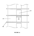
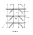
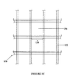
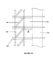
- FIG. 1A examples of the present state of the art for the construction of mid and high-rise buildings is shown, namely using reinforced concrete shear walls 110 ( Fig. 1A ) , structural steel braced frames 120 ( Fig. 1B ) , structural steel or reinforced concrete moment frames 130 ( Fig. 1C ) and combinations thereof 140 ( Fig. 1D ).
- the coupling beams 116, 128, 134, 144
- lateral braces 126 , 148
- a structure 110 using reinforced concrete shear walls 114 has concrete coupling beams 116 located in the openings 112 between the shear walls 114 .
- a structure 120 using steel columns 124 and braces 126 as shown in Figure 1B has steel coupling beams 128 located in the openings 122 between the columns 124 .
- An alternative steel structure 130 consisting only of columns 132 and coupling beams 134 in the openings 136 is shown in Figure 1C .
- the last structure shown in Figure 1D is a combination structure 140 , with concrete shear walls 142 and steel columns 150 and braces 148 separated by an opening 146 and joined by coupling beams 144 .
- the damping system or damper of an embodiment of the invention replaces one or more of the coupling beams ( 116, 128, 134, 144 ) or lateral bracing elements ( 126, 148 ) of the structures shown in Figures 1A - 1D .
- the damper 10 merely replaces the coupling beams or lateral bracing and fits within the area otherwise occupied by the coupling beams or lateral bracing. In doing so, when the building is subject to dynamic wind or seismic loads, the damper 10 is deformed and provides supplemental damping to the system.
- the damping system 10 is comprised of a first set of steel plates 310 interdigital with a second set of one or more similar steel plates 312 and coupled thereto by way of interposed layers of energy dissipating material 320 firmly adhered thereto by layers of adhesive.
- the ends of the two sets of plates opposite the coupled ends are structurally engaged with a pair of adjacent lateral load resisting elements 330 i.e. concrete shear walls, by embedding the ends therein or by bolting the ends to the walls in secure fashion.
- the plates 310, 312 are sufficiently rigid to provide the necessary structural integrity to the building and to follow the movement of the lateral load resisting elements 330, thus accentuating the differential movement between the two ends of the lateral load resisting elements 330, which in turn shears the energy dissipating material 320 between the two sets of plates 310, 312.
- Figure 3 discloses an example of a configuration of the damping system comprising four plates 310 connected to five plates 312 .
- the four plates 310 are coupled to the five plates 312 by way of disks of energy dissipating material 320 .
- the energy dissipating material 320 used is a high damping rubber or a high damping visco-elastic material or any other material capable of dissipating energy (either displacement dependent, or velocity dependent).
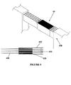
- Figure 4 discloses another example of a damping system 10 according to the invention and comprising a first set of four plates 410 connected as in Figure 3 to a second set of five plates 412 by larger, rectangular shaped sections of energy dissipating material 420 . Variations in the number of plates used, and the length, width, thickness and shape of the energy dissipating material can be used to tune the damping system to the particular application to maximize its damping effect. Furthermore, Figure 4 discloses an anchorage system 414 at one end of the plates 412 for anchoring the damping system 10 to the lateral load resisting elements 430 .
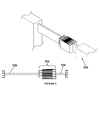
- Figure 5 discloses a configuration of the damping system 10 where the energy dissipating portion of the damper 510 is separately constructed and then connected to rigid extension elements 520, which, in turn are configured to be structurally engaged with the lateral load resisting elements 530 at a later time, for example at a construction site.
- the plates are joined together in sets for coupling to the rigid extension elements.
- Figure 6 discloses a structure 610 undergoing lateral deformation.
- the coupling beams 616 connecting the shear walls 614 are deformed, as well as the damping system 10 .
- Preferred embodiments of the invention thus utilize the in-plane relative deformations, in both orthogonal directions, between two or more lateral load resisting structural elements, regardless of composition, to provide additional damping.
- to the preferred embodiments further provide a damping system capable of being installed without significant changes to the architectural and structural configuration of the building structure in which it is to be installed, and one that is easily constructed and provides a simple replacement for conventional damping systems.
- the energy dissipating material can be chosen from a wide variety of materials, such as natural or synthetic rubber (SBR, polybutadiene, polyisoprene, butyl, etc.), a choice which is within the skill of the art.
- SBR natural or synthetic rubber
- polybutadiene polybutadiene
- polyisoprene butyl, etc.
Landscapes
- Engineering & Computer Science (AREA)
- Architecture (AREA)
- Environmental & Geological Engineering (AREA)
- General Engineering & Computer Science (AREA)
- Business, Economics & Management (AREA)
- Emergency Management (AREA)
- Civil Engineering (AREA)
- Structural Engineering (AREA)
- Mechanical Engineering (AREA)
- Physics & Mathematics (AREA)
- Acoustics & Sound (AREA)
- Aviation & Aerospace Engineering (AREA)
- Health & Medical Sciences (AREA)
- Child & Adolescent Psychology (AREA)
- Electromagnetism (AREA)
- Buildings Adapted To Withstand Abnormal External Influences (AREA)
- Vibration Prevention Devices (AREA)
- Vibration Dampers (AREA)
Description
- The present invention relates to the field of damping systems for buildings, bridges and other structures. In particular, it relates to a new configuration damper, for interconnecting two elements of a structure that undergo relative movements and deformations, that increases the level of damping when the overall structure is subjected to a loading condition. The new configuration damper aids in controlling displacements, velocities and accelerations under dynamic loading in structural systems.
- Modem buildings, using typical construction components such as reinforced concrete shear walls, structural steel braced frames, structural steel or reinforced concrete moment frames or combinations thereof, have low inherent damping properties. Due to this low inherent damping, high-rise buildings, in particular, tend to be susceptible to excessive vibrations caused by dynamic loads. Excessive accelerations and torsional velocities can cause occupant discomfort, while excessive displacements can cause damage to non-structural and structural elements. For this reason it is advantageous to provide additional sources of damping to control these excessive vibrations and reduce the overall building response to dynamic loads.
- Currently available systems for controlling displacements, velocities and accelerations in such structures consist of passive systems such as supplemental dampers and vibration absorbers as well as active systems.
- Passive supplemental dampers such as hysteretic, viscous and visco-elastic dampers are currently used in typical braced configurations and are activated under axial deformations. While this may be effective in adding damping to some structural configurations, where under this typical braced configuration the brace elements undergo significant axial deformations, they are less effective for other structural systems, such as high rise buildings where the primary mode of lateral deformation does not cause sufficient axial deformation in typical bracing elements to actuate such dampers. In order to increase the deformations to an extent sufficient to activate the dampers, special configurations using toggle bracers or scissor braces to amplify the displacements are used.
- Vibration absorbers such as Tuned Mass Dampers (TMD) and Tuned Liquid Dampers (TLD) are also used to reduce the deflections, velocities and accelerations of such structures. They typically consist of a mechanical vibrating system installed on the top floor of buildings in order to maximize their effectiveness. This has the disadvantage of using up some of the most valuable real estate within the building in addition to being expensive to design and to build. They also act in a limited frequency range as they must be tuned to a single mode of vibration.
- Active systems require an external power source, an actuating force and extensive hardware and software control systems. As a result, they are expensive to design and implement, and are susceptible to power outages or failure of the control system.
-
JP 2003-239220 -
JP H11-153194 - It is an object of this invention to provide a new damping system for structures which overcomes at least one of the disadvantages of the existing systems. In particular, it is an object of the invention that the damping system provides additional damping to a structure.
- The present invention provides, from one aspect, a structure with increased damping according to claim 1. Energy dissipating material is interposed between the members of the respective sets of plates. Suitable energy dissipating materials are known in the art and include materials with sufficient strength to withstand lateral deformation that occurs in the structure, without tearing or being otherwise permanently deformed, while having the ability to dissipate the energy absorbed from the lateral deformation. When the two walls move relative to one another, e.g. in high winds, in-plane relative deformation, in both orthogonal directions, of the walls are dampened by the activation of the energy dissipating material between the sets of plates as a consequence of the relative displacement fo the plates with respect to each other.
- Preferably, the two sets of plates comprise a plurality of substantially parallel, spaced-apart plates, the plates of the first set being interdigitated with the plates of the second set. Preferably also, the sets of plates are attached to the two opposite ends of two different lateral load-resisting elements (shear walls, steel braces or columns forming part of moment frames) located in the same plane at certain levels of the structure. Extension elements may be used at either or both ends of the damper to extend its length to accommodate the distance between lateral load-resisting elements.
- Other and further advantages and features of the invention will be apparent to those skilled in the art from the following detailed description thereof, taken in conjunction with the accompanying drawings.
- The invention will now be described in more detail, by way of example only, with reference to the accompanying drawings, in which like numbers refer to like elements, wherein:
-
Figure 1A is a side view of coupled shear wall in a typical building; -
Figure 1B is a side view of a structural steel braced frame in a typical building; -
Figure 1C is a side view of a structural steel or reinforced concrete moment frame in a typical building; -
Figure 1D is a side view of a combination of lateral load resisting systems, a structural steel braced frame and reinforced concrete shear wall in a typical building; -
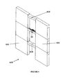
Figure 2A is a side view of two shear walls in a high-rise building with the disclosed invention present coupled between walls; -
Figure 2B is a side view of a structural steel braced frame in a high-rise building with the disclosed invention present coupled between braced frames; -
Figure 2C is a side view of a structural steel or reinforced concrete moment frame in a high-rise building with an embodiment of the disclosed invention present coupled between moment resisting frames; -
Figure 2D is a side view of a combination of lateral load resisting systems, a structural steel braced frame coupled to a reinforced concrete shear wall in a high-rise building with an embodiment of the disclosed invention present coupled between the steel brace frame and the concrete shear wall; -
Figure 3 is a series of views (orthogonal, fragmentary, plan and side elevation) of a configuration of the invention comprising four steel plates coupled to five steel plates and four layers of high damping material sandwiched there between; -
Figure 4 is a pair of views (orthogonal and plan of an alternative configuration of the energy dissipating material with a proposed anchor system and an example of the coupling zone configuration, with the damper coupled between two shear walls; -
Figure 5 is a pair of views (orthogonal and plan) an embodiment of the invention in which optional extension members are used to configure the damper system to be coupled between two shear walls; and -
Figure 6 is an orthogonal view of two shear walls undergoing deformation with the disclosed invention present coupled between the walls. - Referring now to
Figures 1A - 1D , examples of the present state of the art for the construction of mid and high-rise buildings is shown, namely using reinforced concrete shear walls 110 (Fig. 1A ), structural steel braced frames 120 (Fig. 1B ), structural steel or reinforced concrete moment frames 130 (Fig. 1C ) and combinations thereof 140 (Fig. 1D ). As a building is subject to wind or seismic loads, the coupling beams (116, 128, 134, 144) or lateral braces (126, 148) are deformed, without providing any significant damping. - Referring to
Figure 1A , astructure 110 using reinforcedconcrete shear walls 114 hasconcrete coupling beams 116 located in theopenings 112 between theshear walls 114. Similarly, astructure 120 usingsteel columns 124 andbraces 126, as shown inFigure 1B hassteel coupling beams 128 located in theopenings 122 between thecolumns 124. Analternative steel structure 130, consisting only ofcolumns 132 andcoupling beams 134 in theopenings 136 is shown inFigure 1C . The last structure shown inFigure 1D is acombination structure 140, withconcrete shear walls 142 andsteel columns 150 andbraces 148 separated by anopening 146 and joined bycoupling beams 144. - In
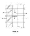
Figures 2A - 2D , the damping system or damper of an embodiment of the invention, generally designated 10 described herein replaces one or more of the coupling beams (116, 128, 134, 144) or lateral bracing elements (126, 148) of the structures shown inFigures 1A - 1D . There is no loss in interior space by doing so, as thedamper 10 merely replaces the coupling beams or lateral bracing and fits within the area otherwise occupied by the coupling beams or lateral bracing. In doing so, when the building is subject to dynamic wind or seismic loads, thedamper 10 is deformed and provides supplemental damping to the system. - Referring variously to
Figures 3-5 , thedamping system 10 is comprised of a first set ofsteel plates 310 interdigital with a second set of one or moresimilar steel plates 312 and coupled thereto by way of interposed layers ofenergy dissipating material 320 firmly adhered thereto by layers of adhesive. The ends of the two sets of plates opposite the coupled ends are structurally engaged with a pair of adjacent lateralload resisting elements 330 i.e. concrete shear walls, by embedding the ends therein or by bolting the ends to the walls in secure fashion. Theplates load resisting elements 330, thus accentuating the differential movement between the two ends of the lateralload resisting elements 330, which in turn shears theenergy dissipating material 320 between the two sets ofplates Figure 3 discloses an example of a configuration of the damping system comprising fourplates 310 connected to fiveplates 312. The fourplates 310 are coupled to the fiveplates 312 by way of disks ofenergy dissipating material 320. There are eight layers ofenergy dissipating material 320 that undergo shear deformations when the lateralload resisting elements 330 to which they are attached undergo lateral deformations. - The
energy dissipating material 320 used is a high damping rubber or a high damping visco-elastic material or any other material capable of dissipating energy (either displacement dependent, or velocity dependent). -
Figure 4 discloses another example of a dampingsystem 10 according to the invention and comprising a first set of fourplates 410 connected as inFigure 3 to a second set of fiveplates 412 by larger, rectangular shaped sections ofenergy dissipating material 420. Variations in the number of plates used, and the length, width, thickness and shape of the energy dissipating material can be used to tune the damping system to the particular application to maximize its damping effect. Furthermore,Figure 4 discloses ananchorage system 414 at one end of theplates 412 for anchoring the dampingsystem 10 to the lateralload resisting elements 430. -
Figure 5 discloses a configuration of the dampingsystem 10 where the energy dissipating portion of thedamper 510 is separately constructed and then connected torigid extension elements 520, which, in turn are configured to be structurally engaged with the lateralload resisting elements 530 at a later time, for example at a construction site. In the configuration shown, the plates are joined together in sets for coupling to the rigid extension elements. -
Figure 6 discloses astructure 610 undergoing lateral deformation. The coupling beams 616 connecting theshear walls 614 are deformed, as well as the dampingsystem 10. - Preferred embodiments of the invention thus utilize the in-plane relative deformations, in both orthogonal directions, between two or more lateral load resisting structural elements, regardless of composition, to provide additional damping.
- They provide a damping system be relatively inexpensive, compared to current damping systems.
- to the preferred embodiments further provide a damping system capable of being installed without significant changes to the architectural and structural configuration of the building structure in which it is to be installed, and one that is easily constructed and provides a simple replacement for conventional damping systems.
- While the embodiment of the invention described herein relates to buildings subjected to lateral loads such as wind loads, seismic loads, and blast loads, other useful applications of this invention, including, but not limited to other structures, will be apparent to those skilled in the art.
- This concludes the description of a presently preferred embodiment of the invention. The foregoing description has been presented for the purpose of illustration and is not intended to be exhaustive or to limit the invention to the precise form disclosed. Many modifications and variations are possible in light of the above teaching and will be apparent to those skilled in the art. For example, while the plates constituting the first and second sets have been described as made from steel, any material sufficiently rigid to provide the necessary structural integrity to the building and to follow the movement of the lateral load resisting elements such as walls or beams could be used, such as other metals and alloys, high strength resin reinforced composites and the like. Also, the energy dissipating material can be chosen from a wide variety of materials, such as natural or synthetic rubber (SBR, polybutadiene, polyisoprene, butyl, etc.), a choice which is within the skill of the art. The scope of the invention is limited not by this description but by the claims that follow.
Claims (4)
- A structure with increased damping, comprising:a first lateral-load-resisting structural element (330);a second lateral-load-resisting structural element located adjacent the first lateral-load-resisting structural element (330);at least one damping system (10) located in between the first lateral-load-resisting structural element and the second lateral-load-resisting structural element, and replacing a coupling beam otherwise used to connect the first lateral-load-resisting structural element and the second lateral-load-resisting structural element, said damping system including:a first set of plates (310) having a first end embedded in said first lateral-load-resisting structural element within said structure; wherein said first lateral-load-resisting structural element comprises a concrete shear wall;a second set of plates (312) having a second end embedded in said second lateral-load-resisting structural element within said structure,and coupling means effective to couple said first set of plates to said second set of plates, the coupling means comprising an energy dissipating material (320).
- The structure of claim 1, wherein said structure includes at least one said damping system per floor of said structure.
- The structure of claim 1, wherein the second lateral-load-resisting structural element is a steel column (150) and the first lateral load-resisting structural element is a concrete shear wall (142).
- The structure of claim 1, wherein the first lateral-load-resisting element is a first shear wall (614) and the second lateral-load-resisting element is a second shear wall (614).
Applications Claiming Priority (2)
| Application Number | Priority Date | Filing Date | Title |
|---|---|---|---|
| CA002524547A CA2524547A1 (en) | 2005-10-26 | 2005-10-26 | Fork configuration dampers and method of using same |
| PCT/CA2006/000985 WO2007048217A1 (en) | 2005-10-26 | 2006-06-16 | Fork configuration dampers and method of using same |
Publications (3)
| Publication Number | Publication Date |
|---|---|
| EP1948878A1 EP1948878A1 (en) | 2008-07-30 |
| EP1948878A4 EP1948878A4 (en) | 2014-03-19 |
| EP1948878B1 true EP1948878B1 (en) | 2015-10-28 |
Family
ID=37965150
Family Applications (1)
| Application Number | Title | Priority Date | Filing Date |
|---|---|---|---|
| EP06761059.2A Active EP1948878B1 (en) | 2005-10-26 | 2006-06-16 | Structure with increased damping by means of fork configuration dampers |
Country Status (8)
| Country | Link |
|---|---|
| US (2) | US7987639B2 (en) |
| EP (1) | EP1948878B1 (en) |
| JP (1) | JP2009513898A (en) |
| KR (1) | KR101379591B1 (en) |
| CN (1) | CN101316973B (en) |
| CA (2) | CA2524547A1 (en) |
| ES (1) | ES2558585T3 (en) |
| WO (1) | WO2007048217A1 (en) |
Families Citing this family (36)
| Publication number | Priority date | Publication date | Assignee | Title |
|---|---|---|---|---|
| ES2358936B1 (en) * | 2008-04-10 | 2012-03-21 | Universitat De Girona | MODULAR POWER DISSIPATION SYSTEM. |
| JP4729132B2 (en) * | 2009-03-12 | 2011-07-20 | 新日本製鐵株式会社 | Linked hardware, vibration control structure, and building structure |
| JP5175250B2 (en) * | 2009-07-31 | 2013-04-03 | 株式会社神戸製鋼所 | Vibration reduction member |
| JP5570605B2 (en) * | 2009-09-25 | 2014-08-13 | ファウ・エス・エル・インターナツイオナール・アクチエンゲゼルシヤフト | Method and structure for dampening motion in a building |
| CA2820820C (en) * | 2011-01-14 | 2013-12-31 | Constantin Christopoulos | Coupling member for damping vibrations in building structures |
| CN102162304B (en) * | 2011-03-09 | 2012-06-20 | 中国建筑第八工程局有限公司 | Construction method for installing viscous damper |
| US8941814B2 (en) * | 2011-06-20 | 2015-01-27 | Nikon Corporation | Multiple-blade holding devices |
| CN102322099A (en) * | 2011-06-23 | 2012-01-18 | 河南理工大学 | Structure for preventing wall bodies in mining areas from mining-induced deformation |
| ES2585208T3 (en) * | 2011-07-15 | 2016-10-04 | Damptech A/S | Passive shock absorber |
| US8607513B2 (en) | 2011-12-30 | 2013-12-17 | Panelclaw, Inc. | Thermal growth compensators, systems, and methods |
| US8844205B2 (en) | 2012-01-06 | 2014-09-30 | The Penn State Research Foundation | Compressed elastomer damper for earthquake hazard reduction |
| US10655328B2 (en) * | 2012-05-24 | 2020-05-19 | The University Of Kentucky Research Foundation | Structural reinforcement, reinforced structural member and related method |
| US8827586B2 (en) * | 2012-06-27 | 2014-09-09 | The Boeing Company | Damping mechanical linkage |
| US9163424B2 (en) * | 2013-10-11 | 2015-10-20 | The Governing Council Of The University Of Toronto | Viscous wall coupling damper |
| EP2921612B1 (en) * | 2014-03-18 | 2016-05-18 | Maurer Söhne Engineering GmbH & Co. KG | Energy dissipating device |
| CN103924666A (en) * | 2014-04-11 | 2014-07-16 | 北京工业大学 | Self-reset pre-stressed buckling-prevention herringbone tubular veneer supporting system for industrial assembly type multi-layer and high-rise steel structures |
| RU2558818C1 (en) * | 2014-07-10 | 2015-08-10 | Олег Савельевич Кочетов | Single-use shock absorber with damaged elements |
| RU2558035C1 (en) * | 2014-07-10 | 2015-07-27 | Олег Савельевич Кочетов | Shock absorber of single action |
| WO2016071879A1 (en) * | 2014-11-07 | 2016-05-12 | University Of Ottawa | Seismic retrofitting buckling restrained brace |
| US9752645B1 (en) * | 2016-04-20 | 2017-09-05 | Hutchinson Antivibration Systems Inc. | Anti-vibration device |
| TR201607751A2 (en) | 2016-06-08 | 2017-12-21 | Ali Salem Milani | Torsional Hysteretic Dumper |
| CN106639465B (en) * | 2016-11-15 | 2018-09-28 | 东南大学 | A kind of end has the energy-dissipating type buckling induction support of four folding line type of varied angle induction unit |
| RU2642190C1 (en) * | 2017-01-13 | 2018-01-24 | Олег Савельевич Кочетов | Single action shock absorber with breakable elements |
| CA3059998C (en) | 2017-04-13 | 2023-02-28 | Novel Structures, LLC | Member-to-member laminar fuse connection |
| US10544577B2 (en) * | 2017-04-13 | 2020-01-28 | Novel Structures, LLC | Member-to-member laminar fuse connection |
| NL2022001A (en) * | 2017-12-15 | 2019-06-21 | Asml Netherlands Bv | Damper device manufacturing method, lithographic apparatus, projection system, and device manufacturing method |
| CN107939137A (en) * | 2017-12-27 | 2018-04-20 | 华侨大学 | A kind of marmem piezoelectric friction damper device |
| JP7042145B2 (en) * | 2018-04-05 | 2022-03-25 | 株式会社鷺宮製作所 | Test equipment using a seismic isolation damper test fixing jig and a seismic isolation damper test fixing jig |
| CN109694008B (en) * | 2019-01-02 | 2020-06-30 | 中国建筑第八工程局有限公司 | Shearing energy dissipation wall attaching rod and using method thereof |
| CN110735538B (en) * | 2019-08-20 | 2023-01-31 | 东南大学 | Assembly type reinforcing structure with external contact surface energy consumption of existing structure |
| CN110805201A (en) * | 2019-11-21 | 2020-02-18 | 大连交通大学 | Replaceable coupling beam with dual energy consumption capability |
| US11879264B2 (en) | 2020-04-04 | 2024-01-23 | Kinetica Dynamics Inc. | Dual-phase vibration damping building coupling member with lock-up |
| CN113756458B (en) * | 2020-06-05 | 2024-03-19 | 南华大学 | Piezoelectric viscous damper |
| CN112854557A (en) * | 2021-01-07 | 2021-05-28 | 中国二十冶集团有限公司 | Shear wall device and combined shear wall system |
| CN113606283B (en) * | 2021-07-30 | 2024-04-16 | 安徽工程大学 | Intelligent automobile vibration reduction and energy recovery power generation device |
| CN113802911B (en) * | 2021-11-01 | 2022-11-18 | 西安建筑科技大学 | TMD-like structure system based on C-shaped shell shock insulation layer |
Family Cites Families (30)
| Publication number | Priority date | Publication date | Assignee | Title |
|---|---|---|---|---|
| US4039050A (en) * | 1969-05-13 | 1977-08-02 | Monsanto Company | Damping system |
| US3691712A (en) * | 1969-05-13 | 1972-09-19 | Monsanto Co | Damping system |
| US3605953A (en) * | 1969-05-26 | 1971-09-20 | Minnesota Mining & Mfg | Bidirectional damping unit |
| NZ201015A (en) * | 1982-06-18 | 1986-05-09 | New Zealand Dev Finance | Building support:cyclic shear energy absorber |
| US4761925A (en) * | 1986-03-31 | 1988-08-09 | Bridgestone Corporation | Anti-seismic rubber bearing |
| US5271197A (en) * | 1986-09-26 | 1993-12-21 | Shimizu Construction Co., Ltd. | Earthquake resistant multi-story building |
| JP2534171B2 (en) * | 1991-07-24 | 1996-09-11 | 新日本製鐵株式会社 | Vibration suppression device for buildings |
| DE4135370C1 (en) * | 1991-10-26 | 1992-12-24 | Mtu Friedrichshafen Gmbh | |
| US5842312A (en) * | 1995-03-01 | 1998-12-01 | E*Sorb Systems | Hysteretic damping apparati and methods |
| TW295612B (en) * | 1995-07-21 | 1997-01-11 | Minnesota Mining & Mfg | |
| AU1401997A (en) * | 1996-01-12 | 1997-08-01 | Penguin Engineering Limited | Energy absorber |
| JP3514586B2 (en) * | 1996-06-03 | 2004-03-31 | 鹿島建設株式会社 | High rigidity damper |
| JPH10220062A (en) * | 1997-02-10 | 1998-08-18 | Shimizu Corp | Vibration damping structure for building |
| JP2966807B2 (en) * | 1997-03-21 | 1999-10-25 | 戸田建設株式会社 | Damping frame |
| US6233884B1 (en) * | 1997-10-20 | 2001-05-22 | Steven B. Tipping | Method and apparatus to control seismic forces, accelerations, and displacements of structures |
| JPH11153194A (en) | 1997-11-20 | 1999-06-08 | Nippon Steel Corp | Damping member integrating elasto-plastic and visco-elastic damper |
| JPH11343675A (en) * | 1998-04-01 | 1999-12-14 | Mitsubishi Heavy Ind Ltd | Damping device and damping structure |
| JP3864363B2 (en) * | 1998-09-02 | 2006-12-27 | 清水建設株式会社 | Viscous damping wall mounting structure and mounting method |
| CN1413282A (en) * | 2000-10-24 | 2003-04-23 | 奥依列斯工业株式会社 | Vibration control structure |
| JP2002194917A (en) * | 2000-12-25 | 2002-07-10 | Building Research Institute | Earthquake-resistant structure of frame |
| JP2002235454A (en) * | 2001-02-07 | 2002-08-23 | Toyo Tire & Rubber Co Ltd | Vibration damper device |
| JP2003049558A (en) * | 2001-08-07 | 2003-02-21 | Kazuhiko Kasai | Vibration control stud |
| JP2003239220A (en) | 2002-02-18 | 2003-08-27 | Shimizu Corp | Vibration control elevated structure |
| US7174680B2 (en) * | 2002-05-29 | 2007-02-13 | Sme Steel Contractors, Inc. | Bearing brace apparatus |
| JP2004197402A (en) * | 2002-12-18 | 2004-07-15 | Shimizu Corp | Earthquake control structural building |
| JP4070616B2 (en) * | 2003-01-10 | 2008-04-02 | カヤバ工業株式会社 | Damping apparatus and damping method |
| KR100516332B1 (en) * | 2003-06-11 | 2005-09-23 | 재단법인 포항산업과학연구원 | Steel structure equipped with connection damper |
| JP3856783B2 (en) * | 2003-10-21 | 2006-12-13 | 等 塩原 | Seismic frame using damper integrated brace and oil damper used for it |
| CN1973098B (en) * | 2004-03-03 | 2010-07-28 | 波利瓦洛尔合股公司 | Self-centering energy dissipative brace apparatus with tensioning elements |
| US7712266B2 (en) * | 2007-05-22 | 2010-05-11 | Skidmore Owings & Merrill Llp | Seismic structural device |
-
2005
- 2005-10-26 CA CA002524547A patent/CA2524547A1/en not_active Abandoned
-
2006
- 2006-06-16 ES ES06761059.2T patent/ES2558585T3/en active Active
- 2006-06-16 CN CN200680040409XA patent/CN101316973B/en active Active
- 2006-06-16 WO PCT/CA2006/000985 patent/WO2007048217A1/en active Application Filing
- 2006-06-16 CA CA2634641A patent/CA2634641C/en active Active
- 2006-06-16 US US12/091,506 patent/US7987639B2/en active Active
- 2006-06-16 EP EP06761059.2A patent/EP1948878B1/en active Active
- 2006-06-16 JP JP2008536887A patent/JP2009513898A/en active Pending
- 2006-06-16 KR KR1020087012596A patent/KR101379591B1/en active IP Right Grant
-
2011
- 2011-06-22 US US13/166,453 patent/US8516753B2/en active Active
Also Published As
| Publication number | Publication date |
|---|---|
| CN101316973B (en) | 2012-02-22 |
| ES2558585T3 (en) | 2016-02-05 |
| CN101316973A (en) | 2008-12-03 |
| JP2009513898A (en) | 2009-04-02 |
| EP1948878A4 (en) | 2014-03-19 |
| US20110283653A1 (en) | 2011-11-24 |
| EP1948878A1 (en) | 2008-07-30 |
| KR20080075847A (en) | 2008-08-19 |
| CA2634641C (en) | 2013-05-21 |
| US20080307722A1 (en) | 2008-12-18 |
| KR101379591B1 (en) | 2014-04-01 |
| US8516753B2 (en) | 2013-08-27 |
| US7987639B2 (en) | 2011-08-02 |
| CA2524547A1 (en) | 2007-04-26 |
| CA2634641A1 (en) | 2007-05-03 |
| WO2007048217A1 (en) | 2007-05-03 |
Similar Documents
| Publication | Publication Date | Title |
|---|---|---|
| EP1948878B1 (en) | Structure with increased damping by means of fork configuration dampers | |
| JP5570605B2 (en) | Method and structure for dampening motion in a building | |
| EP2663699B1 (en) | Coupling member for damping vibrations in building structures | |
| JP2009513898A5 (en) | ||
| KR20100105726A (en) | Connection metal fitting and building with the same | |
| KR101425444B1 (en) | Brace damping system having connection for preventing out plane buckling | |
| JP2023520561A (en) | Two-stage vibration-damped building connection with lock | |
| JP2000213200A (en) | Damping construction | |
| KR102092413B1 (en) | Seismic reinforcement vibration control device having double-plate intermediary damper | |
| JPH10220062A (en) | Vibration damping structure for building | |
| JPH10280727A (en) | Damping frame by composite type damper and damping method | |
| JP3463085B2 (en) | Seismic building | |
| KR102092412B1 (en) | Seismic reinforcement method using vibration control device with double stell plates for building structure | |
| KR102097821B1 (en) | Structure with seismic reinforcement using damper with double stell plate | |
| JPH01102182A (en) | Earthquakeproof wall | |
| JP2001227191A (en) | Damping apparatus | |
| JP2510449Y2 (en) | Vibration control structure of the body | |
| JP2023019256A (en) | Brace structure | |
| JP4911715B2 (en) | Reinforcement structure of buildings and structures | |
| JP2008075392A (en) | Seismic damping column for rigid frame structure | |
| JPH07301023A (en) | Damping structure |
Legal Events
| Date | Code | Title | Description |
|---|---|---|---|
| PUAI | Public reference made under article 153(3) epc to a published international application that has entered the european phase |
Free format text: ORIGINAL CODE: 0009012 |
|
| 17P | Request for examination filed |
Effective date: 20080523 |
|
| AK | Designated contracting states |
Kind code of ref document: A1 Designated state(s): AT BE BG CH CY CZ DE DK EE ES FI FR GB GR HU IE IS IT LI LT LU LV MC NL PL PT RO SE SI SK TR |
|
| RIN1 | Information on inventor provided before grant (corrected) |
Inventor name: CHRISTOPOULOS, CONSTANTIN Inventor name: MONTGOMERY, MICHAEL Inventor name: HASAN, AGHA Inventor name: SMITH, SEAN Inventor name: BENTZ, EVAN Inventor name: COLLINS, MICHAEL Inventor name: KOKAI, TIBOR |
|
| RAP1 | Party data changed (applicant data changed or rights of an application transferred) |
Owner name: THE GOVERNING COUNCIL OF THE UNIVERSITY OF TORONTO Owner name: CHRISTOPOULOS, CONSTANTIN |
|
| DAX | Request for extension of the european patent (deleted) | ||
| A4 | Supplementary search report drawn up and despatched |
Effective date: 20140219 |
|
| RIC1 | Information provided on ipc code assigned before grant |
Ipc: F16F 15/02 20060101ALI20140212BHEP Ipc: E04B 1/98 20060101AFI20140212BHEP Ipc: E04B 5/00 20060101ALI20140212BHEP Ipc: E04H 9/02 20060101ALI20140212BHEP Ipc: F16F 1/50 20060101ALI20140212BHEP Ipc: F16F 1/40 20060101ALI20140212BHEP |
|
| 17Q | First examination report despatched |
Effective date: 20141210 |
|
| GRAP | Despatch of communication of intention to grant a patent |
Free format text: ORIGINAL CODE: EPIDOSNIGR1 |
|
| INTG | Intention to grant announced |
Effective date: 20150626 |
|
| GRAS | Grant fee paid |
Free format text: ORIGINAL CODE: EPIDOSNIGR3 |
|
| GRAA | (expected) grant |
Free format text: ORIGINAL CODE: 0009210 |
|
| AK | Designated contracting states |
Kind code of ref document: B1 Designated state(s): AT BE BG CH CY CZ DE DK EE ES FI FR GB GR HU IE IS IT LI LT LU LV MC NL PL PT RO SE SI SK TR |
|
| REG | Reference to a national code |
Ref country code: GB Ref legal event code: FG4D |
|
| REG | Reference to a national code |
Ref country code: CH Ref legal event code: EP |
|
| REG | Reference to a national code |
Ref country code: AT Ref legal event code: REF Ref document number: 758020 Country of ref document: AT Kind code of ref document: T Effective date: 20151115 |
|
| REG | Reference to a national code |
Ref country code: IE Ref legal event code: FG4D |
|
| REG | Reference to a national code |
Ref country code: DE Ref legal event code: R096 Ref document number: 602006047095 Country of ref document: DE |
|
| REG | Reference to a national code |
Ref country code: ES Ref legal event code: FG2A Ref document number: 2558585 Country of ref document: ES Kind code of ref document: T3 Effective date: 20160205 |
|
| REG | Reference to a national code |
Ref country code: LT Ref legal event code: MG4D |
|
| REG | Reference to a national code |
Ref country code: NL Ref legal event code: MP Effective date: 20151028 |
|
| REG | Reference to a national code |
Ref country code: AT Ref legal event code: MK05 Ref document number: 758020 Country of ref document: AT Kind code of ref document: T Effective date: 20151028 |
|
| PG25 | Lapsed in a contracting state [announced via postgrant information from national office to epo] |
Ref country code: LT Free format text: LAPSE BECAUSE OF FAILURE TO SUBMIT A TRANSLATION OF THE DESCRIPTION OR TO PAY THE FEE WITHIN THE PRESCRIBED TIME-LIMIT Effective date: 20151028 Ref country code: IS Free format text: LAPSE BECAUSE OF FAILURE TO SUBMIT A TRANSLATION OF THE DESCRIPTION OR TO PAY THE FEE WITHIN THE PRESCRIBED TIME-LIMIT Effective date: 20160228 Ref country code: NL Free format text: LAPSE BECAUSE OF FAILURE TO SUBMIT A TRANSLATION OF THE DESCRIPTION OR TO PAY THE FEE WITHIN THE PRESCRIBED TIME-LIMIT Effective date: 20151028 |
|
| PG25 | Lapsed in a contracting state [announced via postgrant information from national office to epo] |
Ref country code: FI Free format text: LAPSE BECAUSE OF FAILURE TO SUBMIT A TRANSLATION OF THE DESCRIPTION OR TO PAY THE FEE WITHIN THE PRESCRIBED TIME-LIMIT Effective date: 20151028 Ref country code: AT Free format text: LAPSE BECAUSE OF FAILURE TO SUBMIT A TRANSLATION OF THE DESCRIPTION OR TO PAY THE FEE WITHIN THE PRESCRIBED TIME-LIMIT Effective date: 20151028 Ref country code: PL Free format text: LAPSE BECAUSE OF FAILURE TO SUBMIT A TRANSLATION OF THE DESCRIPTION OR TO PAY THE FEE WITHIN THE PRESCRIBED TIME-LIMIT Effective date: 20151028 Ref country code: SE Free format text: LAPSE BECAUSE OF FAILURE TO SUBMIT A TRANSLATION OF THE DESCRIPTION OR TO PAY THE FEE WITHIN THE PRESCRIBED TIME-LIMIT Effective date: 20151028 Ref country code: LV Free format text: LAPSE BECAUSE OF FAILURE TO SUBMIT A TRANSLATION OF THE DESCRIPTION OR TO PAY THE FEE WITHIN THE PRESCRIBED TIME-LIMIT Effective date: 20151028 Ref country code: PT Free format text: LAPSE BECAUSE OF FAILURE TO SUBMIT A TRANSLATION OF THE DESCRIPTION OR TO PAY THE FEE WITHIN THE PRESCRIBED TIME-LIMIT Effective date: 20160229 Ref country code: GR Free format text: LAPSE BECAUSE OF FAILURE TO SUBMIT A TRANSLATION OF THE DESCRIPTION OR TO PAY THE FEE WITHIN THE PRESCRIBED TIME-LIMIT Effective date: 20160129 |
|
| REG | Reference to a national code |
Ref country code: FR Ref legal event code: PLFP Year of fee payment: 11 |
|
| PG25 | Lapsed in a contracting state [announced via postgrant information from national office to epo] |
Ref country code: CZ Free format text: LAPSE BECAUSE OF FAILURE TO SUBMIT A TRANSLATION OF THE DESCRIPTION OR TO PAY THE FEE WITHIN THE PRESCRIBED TIME-LIMIT Effective date: 20151028 |
|
| REG | Reference to a national code |
Ref country code: DE Ref legal event code: R097 Ref document number: 602006047095 Country of ref document: DE |
|
| PG25 | Lapsed in a contracting state [announced via postgrant information from national office to epo] |
Ref country code: DK Free format text: LAPSE BECAUSE OF FAILURE TO SUBMIT A TRANSLATION OF THE DESCRIPTION OR TO PAY THE FEE WITHIN THE PRESCRIBED TIME-LIMIT Effective date: 20151028 Ref country code: SK Free format text: LAPSE BECAUSE OF FAILURE TO SUBMIT A TRANSLATION OF THE DESCRIPTION OR TO PAY THE FEE WITHIN THE PRESCRIBED TIME-LIMIT Effective date: 20151028 Ref country code: EE Free format text: LAPSE BECAUSE OF FAILURE TO SUBMIT A TRANSLATION OF THE DESCRIPTION OR TO PAY THE FEE WITHIN THE PRESCRIBED TIME-LIMIT Effective date: 20151028 Ref country code: RO Free format text: LAPSE BECAUSE OF FAILURE TO SUBMIT A TRANSLATION OF THE DESCRIPTION OR TO PAY THE FEE WITHIN THE PRESCRIBED TIME-LIMIT Effective date: 20151028 |
|
| PLBE | No opposition filed within time limit |
Free format text: ORIGINAL CODE: 0009261 |
|
| STAA | Information on the status of an ep patent application or granted ep patent |
Free format text: STATUS: NO OPPOSITION FILED WITHIN TIME LIMIT |
|
| 26N | No opposition filed |
Effective date: 20160729 |
|
| PG25 | Lapsed in a contracting state [announced via postgrant information from national office to epo] |
Ref country code: SI Free format text: LAPSE BECAUSE OF FAILURE TO SUBMIT A TRANSLATION OF THE DESCRIPTION OR TO PAY THE FEE WITHIN THE PRESCRIBED TIME-LIMIT Effective date: 20151028 |
|
| PG25 | Lapsed in a contracting state [announced via postgrant information from national office to epo] |
Ref country code: BE Free format text: LAPSE BECAUSE OF FAILURE TO SUBMIT A TRANSLATION OF THE DESCRIPTION OR TO PAY THE FEE WITHIN THE PRESCRIBED TIME-LIMIT Effective date: 20151028 |
|
| PG25 | Lapsed in a contracting state [announced via postgrant information from national office to epo] |
Ref country code: MC Free format text: LAPSE BECAUSE OF FAILURE TO SUBMIT A TRANSLATION OF THE DESCRIPTION OR TO PAY THE FEE WITHIN THE PRESCRIBED TIME-LIMIT Effective date: 20151028 |
|
| REG | Reference to a national code |
Ref country code: CH Ref legal event code: PL |
|
| REG | Reference to a national code |
Ref country code: IE Ref legal event code: MM4A |
|
| PG25 | Lapsed in a contracting state [announced via postgrant information from national office to epo] |
Ref country code: CH Free format text: LAPSE BECAUSE OF NON-PAYMENT OF DUE FEES Effective date: 20160630 Ref country code: LI Free format text: LAPSE BECAUSE OF NON-PAYMENT OF DUE FEES Effective date: 20160630 |
|
| PG25 | Lapsed in a contracting state [announced via postgrant information from national office to epo] |
Ref country code: IE Free format text: LAPSE BECAUSE OF NON-PAYMENT OF DUE FEES Effective date: 20160616 |
|
| REG | Reference to a national code |
Ref country code: FR Ref legal event code: PLFP Year of fee payment: 12 |
|
| PG25 | Lapsed in a contracting state [announced via postgrant information from national office to epo] |
Ref country code: CY Free format text: LAPSE BECAUSE OF FAILURE TO SUBMIT A TRANSLATION OF THE DESCRIPTION OR TO PAY THE FEE WITHIN THE PRESCRIBED TIME-LIMIT Effective date: 20151028 Ref country code: HU Free format text: LAPSE BECAUSE OF FAILURE TO SUBMIT A TRANSLATION OF THE DESCRIPTION OR TO PAY THE FEE WITHIN THE PRESCRIBED TIME-LIMIT; INVALID AB INITIO Effective date: 20060616 |
|
| REG | Reference to a national code |
Ref country code: FR Ref legal event code: PLFP Year of fee payment: 13 |
|
| PG25 | Lapsed in a contracting state [announced via postgrant information from national office to epo] |
Ref country code: LU Free format text: LAPSE BECAUSE OF NON-PAYMENT OF DUE FEES Effective date: 20160616 |
|
| PG25 | Lapsed in a contracting state [announced via postgrant information from national office to epo] |
Ref country code: BG Free format text: LAPSE BECAUSE OF FAILURE TO SUBMIT A TRANSLATION OF THE DESCRIPTION OR TO PAY THE FEE WITHIN THE PRESCRIBED TIME-LIMIT Effective date: 20151028 |
|
| PGFP | Annual fee paid to national office [announced via postgrant information from national office to epo] |
Ref country code: ES Payment date: 20200804 Year of fee payment: 15 Ref country code: DE Payment date: 20200630 Year of fee payment: 15 |
|
| PGFP | Annual fee paid to national office [announced via postgrant information from national office to epo] |
Ref country code: IT Payment date: 20200626 Year of fee payment: 15 |
|
| REG | Reference to a national code |
Ref country code: DE Ref legal event code: R119 Ref document number: 602006047095 Country of ref document: DE |
|
| PG25 | Lapsed in a contracting state [announced via postgrant information from national office to epo] |
Ref country code: DE Free format text: LAPSE BECAUSE OF NON-PAYMENT OF DUE FEES Effective date: 20220101 |
|
| PG25 | Lapsed in a contracting state [announced via postgrant information from national office to epo] |
Ref country code: IT Free format text: LAPSE BECAUSE OF NON-PAYMENT OF DUE FEES Effective date: 20210616 |
|
| REG | Reference to a national code |
Ref country code: ES Ref legal event code: FD2A Effective date: 20220826 |
|
| PG25 | Lapsed in a contracting state [announced via postgrant information from national office to epo] |
Ref country code: ES Free format text: LAPSE BECAUSE OF NON-PAYMENT OF DUE FEES Effective date: 20210617 |
|
| PGFP | Annual fee paid to national office [announced via postgrant information from national office to epo] |
Ref country code: FR Payment date: 20230613 Year of fee payment: 18 |
|
| PGFP | Annual fee paid to national office [announced via postgrant information from national office to epo] |
Ref country code: TR Payment date: 20230602 Year of fee payment: 18 |
|
| PGFP | Annual fee paid to national office [announced via postgrant information from national office to epo] |
Ref country code: GB Payment date: 20230612 Year of fee payment: 18 |