US8513766B2 - Semiconductor device having a drain-gate isolation portion - Google Patents
Semiconductor device having a drain-gate isolation portion Download PDFInfo
- Publication number
- US8513766B2 US8513766B2 US12/452,169 US45216908A US8513766B2 US 8513766 B2 US8513766 B2 US 8513766B2 US 45216908 A US45216908 A US 45216908A US 8513766 B2 US8513766 B2 US 8513766B2
- Authority
- US
- United States
- Prior art keywords
- insulation film
- drain
- region
- gate insulation
- gate
- Prior art date
- Legal status (The legal status is an assumption and is not a legal conclusion. Google has not performed a legal analysis and makes no representation as to the accuracy of the status listed.)
- Expired - Fee Related, expires
Links
Images


Classifications
-
- H—ELECTRICITY
- H10—SEMICONDUCTOR DEVICES; ELECTRIC SOLID-STATE DEVICES NOT OTHERWISE PROVIDED FOR
- H10D—INORGANIC ELECTRIC SEMICONDUCTOR DEVICES
- H10D62/00—Semiconductor bodies, or regions thereof, of devices having potential barriers
- H10D62/10—Shapes, relative sizes or dispositions of the regions of the semiconductor bodies; Shapes of the semiconductor bodies
- H10D62/13—Semiconductor regions connected to electrodes carrying current to be rectified, amplified or switched, e.g. source or drain regions
- H10D62/149—Source or drain regions of field-effect devices
- H10D62/151—Source or drain regions of field-effect devices of IGFETs
-
- H—ELECTRICITY
- H10—SEMICONDUCTOR DEVICES; ELECTRIC SOLID-STATE DEVICES NOT OTHERWISE PROVIDED FOR
- H10D—INORGANIC ELECTRIC SEMICONDUCTOR DEVICES
- H10D30/00—Field-effect transistors [FET]
- H10D30/01—Manufacture or treatment
- H10D30/021—Manufacture or treatment of FETs having insulated gates [IGFET]
- H10D30/0221—Manufacture or treatment of FETs having insulated gates [IGFET] having asymmetry in the channel direction, e.g. lateral high-voltage MISFETs having drain offset region or extended-drain MOSFETs [EDMOS]
-
- H—ELECTRICITY
- H10—SEMICONDUCTOR DEVICES; ELECTRIC SOLID-STATE DEVICES NOT OTHERWISE PROVIDED FOR
- H10D—INORGANIC ELECTRIC SEMICONDUCTOR DEVICES
- H10D30/00—Field-effect transistors [FET]
- H10D30/60—Insulated-gate field-effect transistors [IGFET]
- H10D30/601—Insulated-gate field-effect transistors [IGFET] having lightly-doped drain or source extensions, e.g. LDD IGFETs or DDD IGFETs
- H10D30/603—Insulated-gate field-effect transistors [IGFET] having lightly-doped drain or source extensions, e.g. LDD IGFETs or DDD IGFETs having asymmetry in the channel direction, e.g. lateral high-voltage MISFETs having drain offset region or extended drain IGFETs [EDMOS]
-
- H—ELECTRICITY
- H10—SEMICONDUCTOR DEVICES; ELECTRIC SOLID-STATE DEVICES NOT OTHERWISE PROVIDED FOR
- H10D—INORGANIC ELECTRIC SEMICONDUCTOR DEVICES
- H10D84/00—Integrated devices formed in or on semiconductor substrates that comprise only semiconducting layers, e.g. on Si wafers or on GaAs-on-Si wafers
- H10D84/01—Manufacture or treatment
- H10D84/0123—Integrating together multiple components covered by H10D12/00 or H10D30/00, e.g. integrating multiple IGBTs
- H10D84/0126—Integrating together multiple components covered by H10D12/00 or H10D30/00, e.g. integrating multiple IGBTs the components including insulated gates, e.g. IGFETs
- H10D84/0165—Integrating together multiple components covered by H10D12/00 or H10D30/00, e.g. integrating multiple IGBTs the components including insulated gates, e.g. IGFETs the components including complementary IGFETs, e.g. CMOS devices
- H10D84/017—Manufacturing their source or drain regions, e.g. silicided source or drain regions
-
- H—ELECTRICITY
- H10—SEMICONDUCTOR DEVICES; ELECTRIC SOLID-STATE DEVICES NOT OTHERWISE PROVIDED FOR
- H10D—INORGANIC ELECTRIC SEMICONDUCTOR DEVICES
- H10D84/00—Integrated devices formed in or on semiconductor substrates that comprise only semiconducting layers, e.g. on Si wafers or on GaAs-on-Si wafers
- H10D84/01—Manufacture or treatment
- H10D84/0123—Integrating together multiple components covered by H10D12/00 or H10D30/00, e.g. integrating multiple IGBTs
- H10D84/0126—Integrating together multiple components covered by H10D12/00 or H10D30/00, e.g. integrating multiple IGBTs the components including insulated gates, e.g. IGFETs
- H10D84/0165—Integrating together multiple components covered by H10D12/00 or H10D30/00, e.g. integrating multiple IGBTs the components including insulated gates, e.g. IGFETs the components including complementary IGFETs, e.g. CMOS devices
- H10D84/0172—Manufacturing their gate conductors
- H10D84/0179—Manufacturing their gate conductors the gate conductors having different shapes or dimensions
-
- H—ELECTRICITY
- H10—SEMICONDUCTOR DEVICES; ELECTRIC SOLID-STATE DEVICES NOT OTHERWISE PROVIDED FOR
- H10D—INORGANIC ELECTRIC SEMICONDUCTOR DEVICES
- H10D84/00—Integrated devices formed in or on semiconductor substrates that comprise only semiconducting layers, e.g. on Si wafers or on GaAs-on-Si wafers
- H10D84/01—Manufacture or treatment
- H10D84/0123—Integrating together multiple components covered by H10D12/00 or H10D30/00, e.g. integrating multiple IGBTs
- H10D84/0126—Integrating together multiple components covered by H10D12/00 or H10D30/00, e.g. integrating multiple IGBTs the components including insulated gates, e.g. IGFETs
- H10D84/0165—Integrating together multiple components covered by H10D12/00 or H10D30/00, e.g. integrating multiple IGBTs the components including insulated gates, e.g. IGFETs the components including complementary IGFETs, e.g. CMOS devices
- H10D84/0181—Manufacturing their gate insulating layers
-
- H—ELECTRICITY
- H10—SEMICONDUCTOR DEVICES; ELECTRIC SOLID-STATE DEVICES NOT OTHERWISE PROVIDED FOR
- H10D—INORGANIC ELECTRIC SEMICONDUCTOR DEVICES
- H10D84/00—Integrated devices formed in or on semiconductor substrates that comprise only semiconducting layers, e.g. on Si wafers or on GaAs-on-Si wafers
- H10D84/01—Manufacture or treatment
- H10D84/0123—Integrating together multiple components covered by H10D12/00 or H10D30/00, e.g. integrating multiple IGBTs
- H10D84/0126—Integrating together multiple components covered by H10D12/00 or H10D30/00, e.g. integrating multiple IGBTs the components including insulated gates, e.g. IGFETs
- H10D84/0165—Integrating together multiple components covered by H10D12/00 or H10D30/00, e.g. integrating multiple IGBTs the components including insulated gates, e.g. IGFETs the components including complementary IGFETs, e.g. CMOS devices
- H10D84/0191—Manufacturing their doped wells
-
- H—ELECTRICITY
- H10—SEMICONDUCTOR DEVICES; ELECTRIC SOLID-STATE DEVICES NOT OTHERWISE PROVIDED FOR
- H10D—INORGANIC ELECTRIC SEMICONDUCTOR DEVICES
- H10D84/00—Integrated devices formed in or on semiconductor substrates that comprise only semiconducting layers, e.g. on Si wafers or on GaAs-on-Si wafers
- H10D84/01—Manufacture or treatment
- H10D84/02—Manufacture or treatment characterised by using material-based technologies
- H10D84/03—Manufacture or treatment characterised by using material-based technologies using Group IV technology, e.g. silicon technology or silicon-carbide [SiC] technology
- H10D84/038—Manufacture or treatment characterised by using material-based technologies using Group IV technology, e.g. silicon technology or silicon-carbide [SiC] technology using silicon technology, e.g. SiGe
-
- H—ELECTRICITY
- H10—SEMICONDUCTOR DEVICES; ELECTRIC SOLID-STATE DEVICES NOT OTHERWISE PROVIDED FOR
- H10D—INORGANIC ELECTRIC SEMICONDUCTOR DEVICES
- H10D84/00—Integrated devices formed in or on semiconductor substrates that comprise only semiconducting layers, e.g. on Si wafers or on GaAs-on-Si wafers
- H10D84/80—Integrated devices formed in or on semiconductor substrates that comprise only semiconducting layers, e.g. on Si wafers or on GaAs-on-Si wafers characterised by the integration of at least one component covered by groups H10D12/00 or H10D30/00, e.g. integration of IGFETs
- H10D84/82—Integrated devices formed in or on semiconductor substrates that comprise only semiconducting layers, e.g. on Si wafers or on GaAs-on-Si wafers characterised by the integration of at least one component covered by groups H10D12/00 or H10D30/00, e.g. integration of IGFETs of only field-effect components
- H10D84/83—Integrated devices formed in or on semiconductor substrates that comprise only semiconducting layers, e.g. on Si wafers or on GaAs-on-Si wafers characterised by the integration of at least one component covered by groups H10D12/00 or H10D30/00, e.g. integration of IGFETs of only field-effect components of only insulated-gate FETs [IGFET]
- H10D84/85—Complementary IGFETs, e.g. CMOS
- H10D84/856—Complementary IGFETs, e.g. CMOS the complementary IGFETs having different architectures than each other, e.g. high-voltage and low-voltage CMOS
-
- H—ELECTRICITY
- H10—SEMICONDUCTOR DEVICES; ELECTRIC SOLID-STATE DEVICES NOT OTHERWISE PROVIDED FOR
- H10D—INORGANIC ELECTRIC SEMICONDUCTOR DEVICES
- H10D84/00—Integrated devices formed in or on semiconductor substrates that comprise only semiconducting layers, e.g. on Si wafers or on GaAs-on-Si wafers
- H10D84/80—Integrated devices formed in or on semiconductor substrates that comprise only semiconducting layers, e.g. on Si wafers or on GaAs-on-Si wafers characterised by the integration of at least one component covered by groups H10D12/00 or H10D30/00, e.g. integration of IGFETs
- H10D84/82—Integrated devices formed in or on semiconductor substrates that comprise only semiconducting layers, e.g. on Si wafers or on GaAs-on-Si wafers characterised by the integration of at least one component covered by groups H10D12/00 or H10D30/00, e.g. integration of IGFETs of only field-effect components
- H10D84/83—Integrated devices formed in or on semiconductor substrates that comprise only semiconducting layers, e.g. on Si wafers or on GaAs-on-Si wafers characterised by the integration of at least one component covered by groups H10D12/00 or H10D30/00, e.g. integration of IGFETs of only field-effect components of only insulated-gate FETs [IGFET]
- H10D84/85—Complementary IGFETs, e.g. CMOS
- H10D84/859—Complementary IGFETs, e.g. CMOS comprising both N-type and P-type wells, e.g. twin-tub
-
- H—ELECTRICITY
- H10—SEMICONDUCTOR DEVICES; ELECTRIC SOLID-STATE DEVICES NOT OTHERWISE PROVIDED FOR
- H10D—INORGANIC ELECTRIC SEMICONDUCTOR DEVICES
- H10D30/00—Field-effect transistors [FET]
- H10D30/60—Insulated-gate field-effect transistors [IGFET]
- H10D30/601—Insulated-gate field-effect transistors [IGFET] having lightly-doped drain or source extensions, e.g. LDD IGFETs or DDD IGFETs
-
- H—ELECTRICITY
- H10—SEMICONDUCTOR DEVICES; ELECTRIC SOLID-STATE DEVICES NOT OTHERWISE PROVIDED FOR
- H10D—INORGANIC ELECTRIC SEMICONDUCTOR DEVICES
- H10D62/00—Semiconductor bodies, or regions thereof, of devices having potential barriers
- H10D62/10—Shapes, relative sizes or dispositions of the regions of the semiconductor bodies; Shapes of the semiconductor bodies
- H10D62/113—Isolations within a component, i.e. internal isolations
- H10D62/115—Dielectric isolations, e.g. air gaps
- H10D62/116—Dielectric isolations, e.g. air gaps adjoining the input or output regions of field-effect devices, e.g. adjoining source or drain regions
-
- H—ELECTRICITY
- H10—SEMICONDUCTOR DEVICES; ELECTRIC SOLID-STATE DEVICES NOT OTHERWISE PROVIDED FOR
- H10D—INORGANIC ELECTRIC SEMICONDUCTOR DEVICES
- H10D62/00—Semiconductor bodies, or regions thereof, of devices having potential barriers
- H10D62/10—Shapes, relative sizes or dispositions of the regions of the semiconductor bodies; Shapes of the semiconductor bodies
- H10D62/17—Semiconductor regions connected to electrodes not carrying current to be rectified, amplified or switched, e.g. channel regions
- H10D62/213—Channel regions of field-effect devices
- H10D62/221—Channel regions of field-effect devices of FETs
- H10D62/235—Channel regions of field-effect devices of FETs of IGFETs
- H10D62/299—Channel regions of field-effect devices of FETs of IGFETs having lateral doping variations
- H10D62/307—Channel regions of field-effect devices of FETs of IGFETs having lateral doping variations the doping variations being parallel to the channel lengths
Definitions
- the present invention relates to a semiconductor device having a MOS transistor.
- MOSFETs metal oxide semiconductor field effect transistors
- FIG. 4 is a sectional view showing the basic construction of such a MOSFET.
- the MOSFET includes, for example, a source region 103 and a drain region 104 provided on opposite sides of a channel region 102 in a surface of a silicon substrate 101 .
- a gate oxide film 105 of SiO 2 (silicon oxide) is provided on the channel region 102 as extending between the source region 103 and the drain region 104 .
- a gate electrode 106 of polysilicon is provided on the gate oxide film 105 .
- the MOSFET having such a construction has a lower breakdown voltage on the order of 5 V, because field concentration (higher electric field) occurs in the vicinity of the drain region 104 .
- An LDD (lightly doped drain) structure is known as capable of relieving the field concentration in the vicinity of the drain region 104 . Even with the LDD structure, it is only possible to increase the breakdown voltage to about 7 V. Therefore, the MOSFET shown in FIG. 4 is generally used as a low breakdown voltage MOSFET.
- a DMOSFET double diffused metal oxide semiconductor field effect transistor
- the DMOSFET is substantially different in construction from the MOSFET shown in FIG. 4 . Therefore, where the DMOSFET and the MOSFET are to be mounted on the same semiconductor substrate, a process for fabricating the DMOSFET and the MOSFET is significantly complicated.
- a surge voltage is inputted into the drain region 104 of the MOSFET having the construction shown in FIG. 4 , a surge current flows to be concentrated on an end portion of the gate oxide film 105 adjacent to the drain region 104 , resulting in breakdown of the end portion of the gate oxide film 105 (so-called ESD (electrostatic discharge) breakdown).
- ESD electrostatic discharge
- the DMOSFET also suffers from ESD breakdown of its gate oxide film, because the gate oxide film contacts an epitaxial layer serving as a drain region.
- Patent Document 1 JP-A-HEI11(1999)-186543
- a semiconductor device which includes a semiconductor layer, a source region provided in a surface layer portion of the semiconductor layer, a drain region provided in the surface of the semiconductor layer in spaced relation from the source region, a gate insulation film provided in opposed relation to a portion of the surface of the semiconductor layer present between the source region and the drain region, a gate electrode provided on the gate insulation film, and a drain-gate isolation portion provided between the drain region and the gate insulation film for isolating the drain region and the gate insulation film from each other in non-contact relation.
- the source region and the drain region are provided in spaced relation in the surface of the semiconductor layer.
- the gate insulation film is provided in opposed relation to the surface portion of the semiconductor layer present between the source region and the drain region.
- the gate electrode is provided on the gate insulation film.
- the drain-gate isolation portion is provided between the drain region and the gate insulation film. The drain-gate isolation portion isolates the drain region and the gate insulation film from each other in non-contact spaced relation.
- the drain region and the gate insulation film are spaced from each other, whereby an electric field generated between the drain region and the gate insulation film is weakened. This prevents the field concentration from occurring in the vicinity of the drain region, thereby preventing the breakdown of the gate insulation film which may otherwise occur due to the field concentration. Therefore, even if the thickness of the gate insulation film is reduced, the MOS transistor has a higher breakdown voltage. In addition, the reduction in the thickness of the gate insulation film reduces ON-resistance. As a result, it is possible to achieve improvement in the breakdown voltage of the MOS transistor as well as the reduction in ON-resistance.
- the MOS transistor Since the drain region and the gate insulation film are spaced from each other, a surge current flows to be distributed into the semiconductor layer from the drain region when a surge voltage is inputted into the drain region. Therefore, the surge current does not flow into the gate insulation film from the drain region, and the field concentration does not occur between the drain region and the gate insulation film. Thus, the MOS transistor has a higher ESD resistance.
- MOS transistor including the source region, the drain region, the gate insulation film and the gate electrode is of a planar type and, therefore, can be easily mounted together with other planar type of MOS transistor on the same semiconductor substrate.
- the semiconductor device may include, for example, a CMOS (complementary metal oxide semiconductor) transistor in addition to the MOS transistor including the source region, the drain region, the gate oxide film and the gate electrode.
- the MOS transistor and the CMOS transistor may be isolated from each other by a device isolation portion formed by filling a trench formed in the surface of the semiconductor layer with a dielectric.
- the drain-gate isolation portion is preferably formed by filling a trench having the same depth as that of the device isolation portion from the surface of the semiconductor layer with the same dielectric as the device isolation portion.
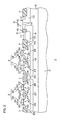
- FIG. 1 is a schematic sectional view showing the construction of a semiconductor device according to one embodiment of the present invention.
- FIG. 2A is a schematic sectional view showing a step of a production process for the semiconductor device.
- FIG. 2B is a schematic sectional view showing a step subsequent to the step shown in FIG. 2A .
- FIG. 2C is a schematic sectional view showing a step subsequent to the step shown in FIG. 2B .
- FIG. 2D is a schematic sectional view showing a step subsequent to the step shown in FIG. 2C .
- FIG. 2E is a schematic sectional view showing a step subsequent to the step shown in FIG. 2D .
- FIG. 3 is a schematic sectional view showing the construction of a semiconductor device according to another embodiment of the present invention.
- FIG. 4 is a schematic sectional view showing the basic construction of a MOSFET.
- FIG. 1 is a schematic sectional view showing the construction of a semiconductor device according to one embodiment of the present invention.
- the semiconductor device 1 includes an HVNMOSFET (high breakdown voltage NMOSFET) 3 , an MVCMOSFET (medium breakdown voltage CMOSFET) 4 and an LVCMOSFET (low breakdown voltage CMOSFET) 5 provided on a P-type semiconductor substrate (e.g., a silicon substrate) 2 .
- HVNMOSFET high breakdown voltage NMOSFET
- MVCMOSFET medium breakdown voltage CMOSFET
- LVCMOSFET low breakdown voltage CMOSFET
- a device isolation portion 7 is provided in a surface layer portion of the semiconductor substrate 2 for isolating the HVNMOSFET 3 , the MVCMOSFET 4 and the LVCMOSFET 5 from each other. Rectangular regions respectively formed with the HVNMOSFET 3 , the MVCMOSFET 4 and the LVCMOSFET 5 are defined by the device isolation portion 7 .
- the device isolation portion 7 has a structure such that a relatively shallow trench (e.g., having a depth of 0.2 to 0.5 ⁇ m from the surface of the semiconductor substrate 2 ) is filled with a dielectric such as SiO 2 . The dielectric portion slightly projects upward from the surface of the semiconductor substrate 2 .
- HVNMOSFET formation region In a rectangular region (hereinafter referred to as “HVNMOSFET formation region”) formed with the HVNMOSFET 3 , a deep N-type well 8 is provided alongside one edge of the device isolation portion 7 that defines the rectangular region.
- the deep N-type well 8 is disposed in an inner portion of the semiconductor substrate 2 , and an uppermost portion thereof is spaced 0.2 to 0.5 ⁇ m downward from the surface of the semiconductor substrate 2 .
- the deep N-type well 8 has a thickness of, for example, 1.5 to 2.5 ⁇ m as measured from the uppermost portion to a lowermost portion thereof.
- drain-side portion The edge of the device isolation portion 7 alongside which the deep N-type well 8 is provided is hereinafter referred to as “drain-side portion”.
- a drain-gate isolation portion 9 having the same structure as the device isolation portion 7 is provided. That is, the drain-gate isolation portion 9 has a structure such that a trench having the same depth as that of the device isolation portion 7 from the surface of the semiconductor substrate 2 is filled with the same dielectric as the device isolation portion 7 .
- the drain-gate isolation portion 9 extends parallel to the drain-side portion of the device isolation portion 7 as being spaced from the drain-side portion by a distance that is smaller than the width of the deep N-type well 8 as measured in a direction in which the drain-gate isolation portion 9 is opposed to the drain-side portion. A lowermost portion of the drain-gate isolation portion 9 is located in the deep N-type well 8 .
- An N-type well 10 is provided between the drain-side portion of the device isolation portion 7 and the drain-gate isolation portion 9 .
- a lowermost portion of the N-type well 10 is located in the deep N-type well 8 .
- An N + -type contact region 11 doped with an N-type impurity at a higher concentration than the N-type well 10 is provided in a surface layer portion of the N-type well 10 , more specifically, between the surface of the semiconductor substrate 2 and the deep N-type well 8 .
- a P-type well 12 is provided alongside an edge of the device isolation portion 7 opposed to the drain-side portion in the HVNMOSFET formation region in the surface layer portion of the semiconductor substrate 2 .
- source-side portion The edge of the device isolation portion 7 opposed to the drain-side portion is hereinafter referred to as “source-side portion”.
- An N-type source region 13 is provided alongside the source-side portion of the device isolation portion 7 in a surface layer portion of the P-type well 12 .
- the source region 13 contacts the source-side portion of the device isolation portion 7 .
- An edge of the source region 13 opposite from the source-side portion is located closer to the source-side portion than to a peripheral edge of the P-type well 12 , and spaced a proper distance from the deep N-type well 8 .
- a gate insulation film 14 of SiO 2 is provided alongside the drain-gate isolation portion 9 between the source-side portion of the device isolation portion 7 and the drain-gate isolation portion 9 on the semiconductor substrate 2 .
- the gate insulation film 14 contacts the drain-gate isolation portion 9 .
- an edge of the gate insulation film 14 opposite from the drain-gate isolating portion 9 is located on the P-type well 12 , and spaced a minute distance from the source region 13 .
- An upper surface of the gate insulation film 14 is generally flush with an upper surface of the drain-gate isolation portion 9 .
- a gate electrode 15 of polysilicon is provided on the gate insulation film 14 as extending to the drain-gate isolation portion 9 .
- An end face of the gate electrode 15 adjacent to the source region 13 is generally flush with an end face of the gate insulation film 14 .
- a sidewall 16 of SiN (silicon nitride) is provided around the gate electrode 15 . Side faces of the gate electrode 15 are covered with the sidewall 16 . Side faces of the gate insulation film 14 are covered with the drain-gate isolation portion 9 and the sidewall 16 .
- a drain region of the HVNMOSFET 3 is defined by the deep N-type well 8 , the N-type well 10 and the contact region 11 .
- the drain-gate isolation portion 9 is disposed between the drain region and the gate insulation film 14 .
- the drain region and the gate insulation film 14 are isolated from each other in non-contact spaced relation by the drain-gate isolation portion 9 .
- the drain region and the gate insulation film 14 are spaced from each other, so that an electric field generated between the drain region and the gate insulation film 14 is weakened. This prevents field concentration from occurring in the vicinity of the drain region and the gate insulation film 14 , thereby preventing breakdown of the gate insulation film 14 which may otherwise occur due to the field concentration. Therefore, even if the gate insulation film 14 has a smaller thickness, a higher breakdown voltage can be achieved. Even if the gate insulation film 14 has a thickness less than 130 ⁇ , for example, a high breakdown voltage on the order of 30 V can be achieved. In addition, ON resistance can be reduced by reducing the thickness of the gate insulation film 14 . As a result, it is possible to achieve improvement in the breakdown voltage of the HVMOSFET 3 as well as the reduction in ON resistance.
- the drain region and the gate insulation film 14 are spaced from each other and most of an interface of the drain region (the deep N-type well 8 ) contacts the semiconductor substrate 2 , a surge current flows to be distributed into the semiconductor substrate 2 from the drain region when a surge voltage is inputted into the drain region. Therefore, the surge current does not flow into the gate insulation film 14 from the drain region, and the field concentration does not occur between the drain region and the gate insulation film 14 .
- the HVNMOSFET 3 has a higher ESD resistance.
- the MVCMOSFET 4 includes an NMOSFET 17 and a PMOSFET 18 of a planar type.
- the NMOSFET 17 and the PMOSFET 18 each have a lower breakdown voltage than the HVNMOSFET 3 (e.g., a breakdown voltage of 3 to 10 V).
- a deep N-type well 19 is provided in a region formed with the MVCMOSFET 4 .
- a PN isolation portion 20 having the same structure as the device isolation portion 7 is provided in this region. That is, the PN isolation portion 20 has a structure such that a trench having the same depth as that of the device isolation portion 7 from the surface of the semiconductor substrate 2 is filled with the same dielectric as the device isolation portion 7 .
- the PN isolation portion 20 divides the MVCMOSFET formation region into an NMOSFET formation region formed with the NMOSFET 17 and a PMOSFET formation region formed with the PMOSFET 18 .
- a P-type well 21 is provided in the NMOSFET formation region in a surface layer portion of the deep N-type well 19 .
- An N + -type source region 23 and an N + -type drain region 24 are provided on opposite sides of a channel region 22 in a surface layer portion of the P-type well 21 . End portions of the source region 23 and the drain region 24 adjacent to the channel region 22 are each located at a smaller depth, and each have a lower impurity concentration. That is, the NMOSFET 17 has an LDD structure for prevention of the short channel effect.
- a gate insulation film 25 of SiO 2 is provided on the channel region 22 .
- the gate insulation film 25 has the same thickness as the gate insulation film 14 of the HVMOSFET 3 .
- a gate electrode 26 of polysilicon is provided on the gate insulation film 25 .
- a sidewall 27 of SiN is provided around the gate electrode 26 . Side surfaces of the gate insulation film 25 and the gate electrode 26 are covered with the sidewall 27 .
- An N-type well 28 is provided in the PMOSFET formation region in the surface layer portion of the deep N-type well 19 .
- a P + -type source region 30 and a P + -type drain region 31 are provided on opposite sides of a channel region 29 in a surface layer portion of the N-type well 28 . End portions of the source region 30 and the drain region 31 adjacent to the channel region 29 are each located at a smaller depth, and each have a lower impurity concentration. That is, the PMOSFET 18 has an LDD structure for prevention of the short channel effect.
- a gate insulation film 32 of SiO 2 is provided on the channel region 29 .
- the gate insulation film 32 has the same thickness as the gate insulation film 14 of the HVMOSFET 3 .
- a gate electrode 33 of polysilicon is provided on the gate insulation film 32 .
- a sidewall 34 of SiN is provided around the gate electrode 33 . Side surfaces of the gate insulation film 32 and the gate electrode 33 are covered with the sidewall 34 .
- the LVCMOSFET 5 includes an NMOSFET 35 and a PMOSFET 36 of a planar type.
- the NMOSFET 35 and the PMOSFET 36 each have a lower breakdown voltage than the NMOSFET 17 and the PMOSFET 18 (e.g., a breakdown voltage of 1 to 5 V).
- a deep N-type well 37 is provided in a region formed with the LVCMOSFET 5 .
- a PN isolation portion 38 having the same structure as the device isolation portion 7 is provided in this region. That is, the PN isolation portion 38 has a structure such that a trench having the same depth as that of the device isolation portion 7 from the surface of the semiconductor substrate 2 is filled with the same dielectric as the device isolation portion 7 .
- the PN isolation portion 38 divides the LVCMOSFET formation region into an NMOSFET formation region formed with the NMOSFET 35 and a PMOSFET formation region formed with the PMOSFET 36 .
- a P-type well 39 is provided in the NMOSFET formation region in a surface layer portion of the deep N-type well 37 .
- An N + -type source region 41 and an N + -type drain region 42 are provided on opposite sides of a channel region 40 in a surface layer portion of the P-type well 39 . End portions of the source region 41 and the drain region 42 adjacent to the channel region 40 are each located at a smaller depth, and each have a lower impurity concentration. That is, the NMOSFET 35 has an LDD structure for prevention of the short channel effect.
- a gate insulation film 43 of SiO 2 is provided on the channel region 40 .
- the gate insulation film 43 has a smaller thickness than the gate insulation film 14 of the HVMOSFET 3 .
- a gate electrode 44 of polysilicon is provided on the gate insulation film 43 .
- a sidewall 45 of SiN is provided around the gate electrode 44 . Side faces of the gate insulation film 43 and the gate electrode 44 are covered with the sidewall 45 .
- An N-type well 46 is provided in the PMOSFET formation region in the surface layer portion of the deep N-type well 37 .
- a P + -type source region 48 and a P + -type drain region 49 are provided on opposite sides of a channel region 47 in a surface layer portion of the N-type well 46 . End portions of the source region 48 and the drain region 49 adjacent to the channel region 47 are each located at a smaller depth, and each have a lower impurity concentration. That is, the PMOSFET 36 has an LDD structure for prevention of the short channel effect.
- a gate insulation film 50 of SiO 2 is provided on the channel region 47 .
- the gate insulation film 50 has a thickness that is smaller than that of the gate insulation film 14 of the HVMOSFET 3 and equal to that of the gate insulation film 43 of the NMOSFET 37 .
- a gate electrode 51 of polysilicon is provided on the gate insulation film 50 .
- a sidewall 52 of SiN is provided around the gate electrode 51 . Side faces of the gate insulation film 50 and the gate electrode 51 are covered with the sidewall 52 .
- a P-type well 53 is provided below the device isolation portion 7 in contact with the device isolation portion 7 .
- FIGS. 2A to 2E are schematic sectional views showing a process sequence of a production process for the semiconductor device 1 .
- trenches for a device isolation portion 7 , a drain-gate isolation portion 9 and PN isolation portions 20 , 38 are formed in a surface layer portion of a semiconductor substrate 2 by reactive ion etching. Thereafter, SiO 2 is deposited on the semiconductor substrate 2 to a thickness such as to entirely fill the trenches by an HDP-CVD (high density plasma chemical vapor deposition) method. Then, a portion of the resulting SiO 2 film present outside the trenches is selectively removed, whereby the SiO 2 film remains only in and above the trenches.
- the selective removal of the SiO 2 film may be achieved by a CMP (chemical mechanical polishing) method.
- a resist film 61 having openings in association with regions to be formed with deep N-type wells 8 , 19 , 37 is formed on the semiconductor substrate 2 by the photolithography technique.
- an N-type impurity e.g., arsenic ions
- the resist film 61 is removed.
- a resist film 62 having openings in association with regions to be formed with N-type wells 10 , 28 , 46 is formed on the semiconductor substrate 2 by the photolithography technique. Then, the N-type impurity is implanted into the semiconductor substrate 2 by using the resist film 62 as a mask, whereby the N-type wells 10 , 28 , 46 are formed. After the implantation of the N-type impurity, the resist film 62 is removed.
- a resist film 63 having openings in association with regions to be formed with P-type wells 12 , 21 , 39 , 53 is formed on the semiconductor substrate 2 by the photolithography technique.
- a P-type impurity e.g., boron ions
- the resist film 63 is removed.
- SiO 2 films 64 are formed on a surface of the semiconductor substrate 2 by a thermal oxidation method. More specifically, a SiO 2 film having a predetermined thickness is formed on the entire surface of the semiconductor substrate 2 in the first thermal oxidation step. Then, a portion of the SiO 2 film present on a region to be formed with an LVCMOSFET 5 is selectively removed.
- a SiO 2 film is formed on a portion of the semiconductor substrate 2 exposed by the selective removal of the SiO 2 film, and portions of the SiO 2 film remaining on regions to be formed with the HVMOSFET 3 and the MVCMOSFET 4 are further grown (the remaining SiO 2 film portions are thickened).
- SiO 2 films 64 are formed as having different thicknesses in the region to be formed with the LVCMOSFET 5 and in the regions to be formed with the HVMOSFET 3 and the HMVCMOSFET 4 .
- a polysilicon film is formed over the SiO 2 films 64 by a thermal CVD method. Thereafter, a portion of the polysilicon film is selectively removed, whereby gate electrodes 15 , 26 , 33 , 44 , 51 are formed.
- the selective removal of the polysilicon film is achieved, for example, by RIE (reactive ion etching).
- an SiN film is formed over the SiO 2 films 64 and then etched back, whereby sidewalls 16 , 27 , 34 , 45 , 52 (see FIG. 1 ) are respectively formed around the gate electrodes 15 , 26 , 33 , 44 , 51 .
- gate insulation films 14 , 25 , 32 , 43 , 50 are formed as shown in FIG. 1 .
- the P-type impurity is implanted into surface layer portions of the N-type wells 28 , 46 to a lower concentration, and the N-type impurity is implanted into surface layer portions of the P-type wells 21 , 39 to a lower concentration. Then, the P-type impurity is implanted into the surfaces of the N-type wells 10 , 28 , 46 to a higher concentration from exposed surface portions of the N-type wells 10 , 28 , 46 , whereby a contact region 11 and drain regions 24 , 31 , 42 , 49 are formed.
- the N-type impurity is implanted into the surfaces of the P-type wells 12 , 21 , 39 to a higher concentration from exposed surface portions of the P-type wells 12 , 21 , 39 , whereby source regions 13 , 23 , 30 , 41 , 48 are formed.
- the semiconductor device having the construction shown in FIG. 1 is produced through the steps described above.
- the drain-gate isolation portion 9 , the device isolation portion 7 and the PN isolation portions 20 , 38 can be formed in the same step. Further, fabrication of the HVNMOSFET 3 can be achieved during fabrication of the MVCMOSFET 4 and the LVCMOSFET 5 . Thus, the HVNMOSFET 3 can be fabricated on the semiconductor substrate 2 on which the MVCMOSFET 4 and the LVCMOSFET 5 are to be mounted without the need for adding an additional step to a process for the fabrication of the MVCMOSFET 4 and the LVCMOSFET 5 .
- An annealing process for activating the ions may be performed as required in addition to the aforementioned process steps.
- FIG. 3 is a schematic sectional view showing the construction of a semiconductor device according to another embodiment of the present invention.
- components corresponding to those shown in FIG. 1 will be denoted by the same reference characters as in FIG. 1 .
- the semiconductor device 1 shown in FIG. 3 includes a P-type epitaxial layer 6 provided on a semiconductor substrate 2 .
- Components of an HVNMOSFET 3 , an MVCMOSFET 4 and an LVCMOSFET 5 , and a device isolation portion 7 which isolates the HVNMOSFET 3 , the MVCMOSFET 4 and the LVCMOSFET 5 from each other are provided in the P-type epitaxial layer 6 .
- This arrangement provides the same effects as the arrangement shown in FIG. 1 .
- the HVNMOSFET 3 is mounted as a high breakdown voltage MOSFET on the semiconductor substrate 2 by way of example, but a high breakdown voltage PMOSFET including semiconductor portions having conductivity types reversed from those of the semiconductor portions of the HVNMOSFET 3 (e.g., including P-type portions instead of the N-type portions) is employed instead of the HVNMOSFET 3 .
Landscapes
- Metal-Oxide And Bipolar Metal-Oxide Semiconductor Integrated Circuits (AREA)
- Insulated Gate Type Field-Effect Transistor (AREA)
- Thin Film Transistor (AREA)
Abstract
Description
- 1: Semiconductor device
- 2: Semiconductor substrate (semiconductor layer)
- 3: HVNMOSFET
- 4: MVCMOSFET
- 5: LVCMOSFET
- 6: P-type epitaxial layer (semiconductor layer)
- 7: Device isolation portion
- 8: Deep N-type well
- 9: Drain-gate isolation portion
- 10: N-type well
- 11: Contact region
- 13: Source region
- 14: Gate insulation film
- 15: Gate electrode
Claims (20)
Applications Claiming Priority (3)
| Application Number | Priority Date | Filing Date | Title |
|---|---|---|---|
| JP2007161493A JP5172223B2 (en) | 2007-06-19 | 2007-06-19 | Semiconductor device |
| JP2007-161493 | 2007-06-19 | ||
| PCT/JP2008/061246 WO2008156140A1 (en) | 2007-06-19 | 2008-06-19 | Semiconductor device |
Related Parent Applications (1)
| Application Number | Title | Priority Date | Filing Date |
|---|---|---|---|
| PCT/JP2008/061246 A-371-Of-International WO2008156140A1 (en) | 2007-06-19 | 2008-06-19 | Semiconductor device |
Related Child Applications (1)
| Application Number | Title | Priority Date | Filing Date |
|---|---|---|---|
| US13/941,458 Continuation US8878294B2 (en) | 2007-06-19 | 2013-07-13 | Semiconductor device having a drain-gate isolation portion |
Publications (2)
| Publication Number | Publication Date |
|---|---|
| US20100102387A1 US20100102387A1 (en) | 2010-04-29 |
| US8513766B2 true US8513766B2 (en) | 2013-08-20 |
Family
ID=40156298
Family Applications (2)
| Application Number | Title | Priority Date | Filing Date |
|---|---|---|---|
| US12/452,169 Expired - Fee Related US8513766B2 (en) | 2007-06-19 | 2008-06-19 | Semiconductor device having a drain-gate isolation portion |
| US13/941,458 Active US8878294B2 (en) | 2007-06-19 | 2013-07-13 | Semiconductor device having a drain-gate isolation portion |
Family Applications After (1)
| Application Number | Title | Priority Date | Filing Date |
|---|---|---|---|
| US13/941,458 Active US8878294B2 (en) | 2007-06-19 | 2013-07-13 | Semiconductor device having a drain-gate isolation portion |
Country Status (3)
| Country | Link |
|---|---|
| US (2) | US8513766B2 (en) |
| JP (1) | JP5172223B2 (en) |
| WO (1) | WO2008156140A1 (en) |
Families Citing this family (6)
| Publication number | Priority date | Publication date | Assignee | Title |
|---|---|---|---|---|
| JP5448788B2 (en) | 2009-12-22 | 2014-03-19 | ルネサスエレクトロニクス株式会社 | Semiconductor device |
| JP2014207361A (en) * | 2013-04-15 | 2014-10-30 | 富士通セミコンダクター株式会社 | Semiconductor device and manufacturing method of the same |
| US20150048875A1 (en) * | 2013-08-19 | 2015-02-19 | Ememory Technology Inc. | High voltage power control system |
| CN113964035B (en) | 2020-07-20 | 2023-05-02 | 无锡华润上华科技有限公司 | Manufacturing method of semiconductor device and semiconductor device |
| TWI888692B (en) * | 2022-01-10 | 2025-07-01 | 聯華電子股份有限公司 | Semiconductor device and method of fabricating the same |
| CN116600571A (en) | 2022-02-11 | 2023-08-15 | 力旺电子股份有限公司 | Resistive Memory Cell and Its Related Array Structure |
Citations (14)
| Publication number | Priority date | Publication date | Assignee | Title |
|---|---|---|---|---|
| JPH08213601A (en) | 1995-01-31 | 1996-08-20 | Sanyo Electric Co Ltd | Semiconductor device and its manufacturing method |
| JPH11186543A (en) | 1997-12-24 | 1999-07-09 | Nec Corp | High breakdown voltage MOSFET and method of manufacturing high breakdown voltage MOSFET |
| US6172401B1 (en) | 1998-06-30 | 2001-01-09 | Intel Corporation | Transistor device configurations for high voltage applications and improved device performance |
| JP2001168210A (en) | 1999-10-27 | 2001-06-22 | Texas Instr Inc <Ti> | Extended drain transistor for integrated circuits |
| US20010009288A1 (en) * | 1995-07-14 | 2001-07-26 | Seiko Instruments Inc. | Semiconductor device and method of fabricating the same |
| US20010040266A1 (en) * | 1997-10-10 | 2001-11-15 | Massimo Pozzoni | Integrated circuit with highly efficient junction insulation |
| US6717204B1 (en) * | 1999-06-23 | 2004-04-06 | Seiko Epson Corporation | Semiconductor devices having a non-volatile memory transistor |
| US20050029616A1 (en) * | 2003-07-14 | 2005-02-10 | Takafumi Noda | Semiconductor device and method for manufacturing the same |
| JP2005045147A (en) | 2003-07-25 | 2005-02-17 | Seiko Epson Corp | Semiconductor device and manufacturing method thereof |
| US20050194646A1 (en) * | 2004-03-04 | 2005-09-08 | Fujitsu Limited | Semiconductor device with shallow trench isolation and its manufacture method |
| US20060113627A1 (en) * | 2004-11-29 | 2006-06-01 | Chung-I Chen | High-voltage transistor device having an interlayer dielectric etch stop layer for preventing leakage and improving breakdown voltage |
| US20060163623A1 (en) | 2005-01-27 | 2006-07-27 | Seiko Epson Corporation | Semiconductor device and manufacturing method thereof |
| JP2006237341A (en) | 2005-02-25 | 2006-09-07 | Seiko Epson Corp | Semiconductor device manufacturing method and semiconductor device |
| US20070128788A1 (en) * | 2005-10-11 | 2007-06-07 | United Microelectronics Corp. | High voltage metal oxide semiconductor device |
-
2007
- 2007-06-19 JP JP2007161493A patent/JP5172223B2/en not_active Expired - Fee Related
-
2008
- 2008-06-19 WO PCT/JP2008/061246 patent/WO2008156140A1/en not_active Ceased
- 2008-06-19 US US12/452,169 patent/US8513766B2/en not_active Expired - Fee Related
-
2013
- 2013-07-13 US US13/941,458 patent/US8878294B2/en active Active
Patent Citations (16)
| Publication number | Priority date | Publication date | Assignee | Title |
|---|---|---|---|---|
| JPH08213601A (en) | 1995-01-31 | 1996-08-20 | Sanyo Electric Co Ltd | Semiconductor device and its manufacturing method |
| US20010009288A1 (en) * | 1995-07-14 | 2001-07-26 | Seiko Instruments Inc. | Semiconductor device and method of fabricating the same |
| US20010040266A1 (en) * | 1997-10-10 | 2001-11-15 | Massimo Pozzoni | Integrated circuit with highly efficient junction insulation |
| JPH11186543A (en) | 1997-12-24 | 1999-07-09 | Nec Corp | High breakdown voltage MOSFET and method of manufacturing high breakdown voltage MOSFET |
| US6172401B1 (en) | 1998-06-30 | 2001-01-09 | Intel Corporation | Transistor device configurations for high voltage applications and improved device performance |
| US6717204B1 (en) * | 1999-06-23 | 2004-04-06 | Seiko Epson Corporation | Semiconductor devices having a non-volatile memory transistor |
| JP2001168210A (en) | 1999-10-27 | 2001-06-22 | Texas Instr Inc <Ti> | Extended drain transistor for integrated circuits |
| US6548874B1 (en) | 1999-10-27 | 2003-04-15 | Texas Instruments Incorporated | Higher voltage transistors for sub micron CMOS processes |
| US20050029616A1 (en) * | 2003-07-14 | 2005-02-10 | Takafumi Noda | Semiconductor device and method for manufacturing the same |
| JP2005045147A (en) | 2003-07-25 | 2005-02-17 | Seiko Epson Corp | Semiconductor device and manufacturing method thereof |
| US20050194646A1 (en) * | 2004-03-04 | 2005-09-08 | Fujitsu Limited | Semiconductor device with shallow trench isolation and its manufacture method |
| US20060113627A1 (en) * | 2004-11-29 | 2006-06-01 | Chung-I Chen | High-voltage transistor device having an interlayer dielectric etch stop layer for preventing leakage and improving breakdown voltage |
| US20060163623A1 (en) | 2005-01-27 | 2006-07-27 | Seiko Epson Corporation | Semiconductor device and manufacturing method thereof |
| JP2006210584A (en) | 2005-01-27 | 2006-08-10 | Seiko Epson Corp | Semiconductor device and manufacturing method thereof |
| JP2006237341A (en) | 2005-02-25 | 2006-09-07 | Seiko Epson Corp | Semiconductor device manufacturing method and semiconductor device |
| US20070128788A1 (en) * | 2005-10-11 | 2007-06-07 | United Microelectronics Corp. | High voltage metal oxide semiconductor device |
Also Published As
| Publication number | Publication date |
|---|---|
| US20100102387A1 (en) | 2010-04-29 |
| US20130292765A1 (en) | 2013-11-07 |
| US8878294B2 (en) | 2014-11-04 |
| JP2009004441A (en) | 2009-01-08 |
| WO2008156140A1 (en) | 2008-12-24 |
| JP5172223B2 (en) | 2013-03-27 |
Similar Documents
| Publication | Publication Date | Title |
|---|---|---|
| US9054133B2 (en) | High voltage trench transistor | |
| US8999769B2 (en) | Integration of high voltage trench transistor with low voltage CMOS transistor | |
| US10134892B2 (en) | High voltage device with low Rdson | |
| US9947770B2 (en) | Self-aligned trench MOSFET and method of manufacture | |
| US7745294B2 (en) | Methods of manufacturing trench isolated drain extended MOS (demos) transistors and integrated circuits therefrom | |
| US8786013B2 (en) | Trench transistor | |
| EP1826815A2 (en) | Semiconductor device and method of manufacturing the same | |
| US8878294B2 (en) | Semiconductor device having a drain-gate isolation portion | |
| US10658505B1 (en) | High voltage device and a method for forming the high voltage device | |
| CN111554744B (en) | Semiconductor device and method for manufacturing semiconductor device | |
| JP6726092B2 (en) | Semiconductor device and manufacturing method thereof | |
| US10629728B1 (en) | Semiconductor device and fabrication method thereof | |
| US7705399B2 (en) | Semiconductor device with field insulation film formed therein | |
| JP2009152442A (en) | Semiconductor device and manufacturing method thereof | |
| JP4899425B2 (en) | Semiconductor device and manufacturing method thereof | |
| JP4150704B2 (en) | Horizontal short channel DMOS | |
| JP5002920B2 (en) | Manufacturing method of semiconductor device | |
| EP3261126B1 (en) | High-voltage semiconductor device and method for manufacturing the same | |
| JP2005175011A (en) | Field effect transistor and its manufacturing method | |
| CN114823904A (en) | Semiconductor structure and forming method thereof |
Legal Events
| Date | Code | Title | Description |
|---|---|---|---|
| AS | Assignment |
Owner name: ROHM CO., LTD.,JAPAN Free format text: ASSIGNMENT OF ASSIGNORS INTEREST;ASSIGNORS:KOJIMA, MITSUO;TAKEI, SHOJI;REEL/FRAME:023704/0196 Effective date: 20091215 Owner name: ROHM CO., LTD., JAPAN Free format text: ASSIGNMENT OF ASSIGNORS INTEREST;ASSIGNORS:KOJIMA, MITSUO;TAKEI, SHOJI;REEL/FRAME:023704/0196 Effective date: 20091215 |
|
| STCF | Information on status: patent grant |
Free format text: PATENTED CASE |
|
| FEPP | Fee payment procedure |
Free format text: PAYOR NUMBER ASSIGNED (ORIGINAL EVENT CODE: ASPN); ENTITY STATUS OF PATENT OWNER: LARGE ENTITY |
|
| FPAY | Fee payment |
Year of fee payment: 4 |
|
| MAFP | Maintenance fee payment |
Free format text: PAYMENT OF MAINTENANCE FEE, 8TH YEAR, LARGE ENTITY (ORIGINAL EVENT CODE: M1552); ENTITY STATUS OF PATENT OWNER: LARGE ENTITY Year of fee payment: 8 |
|
| FEPP | Fee payment procedure |
Free format text: MAINTENANCE FEE REMINDER MAILED (ORIGINAL EVENT CODE: REM.); ENTITY STATUS OF PATENT OWNER: LARGE ENTITY |
|
| LAPS | Lapse for failure to pay maintenance fees |
Free format text: PATENT EXPIRED FOR FAILURE TO PAY MAINTENANCE FEES (ORIGINAL EVENT CODE: EXP.); ENTITY STATUS OF PATENT OWNER: LARGE ENTITY |
|
| STCH | Information on status: patent discontinuation |
Free format text: PATENT EXPIRED DUE TO NONPAYMENT OF MAINTENANCE FEES UNDER 37 CFR 1.362 |
|
| FP | Lapsed due to failure to pay maintenance fee |
Effective date: 20250820 |