US8429855B2 - Window weatherseal with molded weatherstrip - Google Patents
Window weatherseal with molded weatherstrip Download PDFInfo
- Publication number
- US8429855B2 US8429855B2 US12/300,825 US30082507A US8429855B2 US 8429855 B2 US8429855 B2 US 8429855B2 US 30082507 A US30082507 A US 30082507A US 8429855 B2 US8429855 B2 US 8429855B2
- Authority
- US
- United States
- Prior art keywords
- sealing strip
- seal according
- strip
- rigid
- guide slot
- Prior art date
- Legal status (The legal status is an assumption and is not a legal conclusion. Google has not performed a legal analysis and makes no representation as to the accuracy of the status listed.)
- Active, expires
Links
Images


Classifications
-
- B—PERFORMING OPERATIONS; TRANSPORTING
- B29—WORKING OF PLASTICS; WORKING OF SUBSTANCES IN A PLASTIC STATE IN GENERAL
- B29C—SHAPING OR JOINING OF PLASTICS; SHAPING OF MATERIAL IN A PLASTIC STATE, NOT OTHERWISE PROVIDED FOR; AFTER-TREATMENT OF THE SHAPED PRODUCTS, e.g. REPAIRING
- B29C45/00—Injection moulding, i.e. forcing the required volume of moulding material through a nozzle into a closed mould; Apparatus therefor
- B29C45/16—Making multilayered or multicoloured articles
- B29C45/1676—Making multilayered or multicoloured articles using a soft material and a rigid material, e.g. making articles with a sealing part
-
- B—PERFORMING OPERATIONS; TRANSPORTING
- B60—VEHICLES IN GENERAL
- B60J—WINDOWS, WINDSCREENS, NON-FIXED ROOFS, DOORS, OR SIMILAR DEVICES FOR VEHICLES; REMOVABLE EXTERNAL PROTECTIVE COVERINGS SPECIALLY ADAPTED FOR VEHICLES
- B60J10/00—Sealing arrangements
- B60J10/20—Sealing arrangements characterised by the shape
- B60J10/22—Sealing arrangements characterised by the shape having varying cross-section in the longitudinal direction
-
- B—PERFORMING OPERATIONS; TRANSPORTING
- B60—VEHICLES IN GENERAL
- B60J—WINDOWS, WINDSCREENS, NON-FIXED ROOFS, DOORS, OR SIMILAR DEVICES FOR VEHICLES; REMOVABLE EXTERNAL PROTECTIVE COVERINGS SPECIALLY ADAPTED FOR VEHICLES
- B60J10/00—Sealing arrangements
- B60J10/70—Sealing arrangements specially adapted for windows or windscreens
- B60J10/74—Sealing arrangements specially adapted for windows or windscreens for sliding window panes, e.g. sash guides
- B60J10/75—Sealing arrangements specially adapted for windows or windscreens for sliding window panes, e.g. sash guides for sealing the lower part of the panes
-
- B—PERFORMING OPERATIONS; TRANSPORTING
- B29—WORKING OF PLASTICS; WORKING OF SUBSTANCES IN A PLASTIC STATE IN GENERAL
- B29L—INDEXING SCHEME ASSOCIATED WITH SUBCLASS B29C, RELATING TO PARTICULAR ARTICLES
- B29L2031/00—Other particular articles
- B29L2031/001—Profiled members, e.g. beams, sections
- B29L2031/003—Profiled members, e.g. beams, sections having a profiled transverse cross-section
- B29L2031/005—Profiled members, e.g. beams, sections having a profiled transverse cross-section for making window frames
- B29L2031/006—Profiled members, e.g. beams, sections having a profiled transverse cross-section for making window frames and provided with a sealing element
Definitions
- the present invention concerns the field of window seals.
- the invention concerns more particularly the field of window seals to be encased in a frame, intended to be in contact with part of the perimeter of a window, and comprising a guide slot strip consisting of two upward segments and an upper segment, and a sealing strip extending between a low part of one of said upward segments and a high part of the other of said upward segments.
- the window slides in a substantially vertical direction.
- the window In its open position, the window is in a low position, completely or partially retracted into the thickness of the door between the outer and inner surfaces thereof; in changing from its open position to its closed position, the window comes out via the upper edge of the door.
- the window In its closed position, the window is in the high position and the lower part of its perimeter (lower edge, and lower portions of the front and rear edges) remains inserted in the thickness of the door, whilst the upper edge and the front and rear edges come respectively into contact with the upper, front and rear posts forming the door frame.
- a continuous seal (guide slot strip) is encased in these posts, and on the other hand the upper edge of the door is provided with a seal (sealing strip) which comes opposite the window.
- This sealing strip is provided with a slippery coating, for example a flocked lip.
- Flocking is a method that consists of depositing, on an element, hairs perpendicular thereto by an electrostatic means and fixing them with adhesive. These hairs rub on the window when the latter changes from an open to a closed position and vice versa, and have the aim of preventing water or other elements entering the thickness of the door between the outer and inner surfaces thereof.
- the guide slot and sealing strips and the slippery coating for example the flocked lip, are typically made from elastomer, thermoplastic, or thermoplastic elastomer (TPE).
- FIG. 7 depicts a seal according to the prior art.
- This seal comprises a guide slot strip 102 and a sealing strip 110 .
- the guide slot strip is extruded, and the sealing strip consists of an extruded part 119 , and a moulded connection 154 .
- the guide slot strip 102 and the extruded part of the sealing strip 119 often comprise a metal framework.
- the extruded part of the sealing strip 119 is connected to the rear upward segment 104 of the guide slot strip by means of the moulded connection 154 .
- This moulded connection is essential for making a sealed connection between the rear part of the sealing strip 110 and the rear upward segment 104 of the guide slot strip.
- the sealing strip 110 and the guide slot strip 102 are extruded, their junction with the moulded connection 154 necessarily causes the appearance of a first join line 141 between the moulded connection 154 and the rear upward segment 104 of the guide slot strip, and a second join line 142 between the sealing strip 110 and the moulded connection 154 .
- the junction between the sealing strip 110 and the front moulded connection 156 causes the appearance of a third join line 143 .
- These join lines have the appearance of a ridge and are visible, being all the more so the greater the change in shape of the cross-section between the sealing strip 110 and the rear upward segment of the guide slot strip 104 .
- the present invention aims to remedy these drawbacks.
- the invention aims to propose a new type of door window seal that makes it possible to reduce the number of join lines between the guide slot strip and the sealing strip, facilitate manufacturing of the seal, reduce manufacturing costs, and allow better recycling of the strips.
- the sealing strip is moulded in a single piece and comprises an upward curved part, and the sealing strip is attached at least at its upper end to one of the upward segments of the guide slot strip.
- the junction between the sealing strip and one of the upward segments of the guide slot strip is situated close to the upper segment of the guide slot strip.
- the sealing strip is manufactured by bi-injection of a rigid material and a flexible material, defining in the sealing strip a rigid part and a flexible part which are distinct.
- the rigid part can be made from rigid plastic and the flexible part made from elastomer.
- the rigid part of the sealing strip comprises means for holding on said frame.
- the mounting of the seal on the frame is therefore facilitated, its efficiency improved, and its total manufacturing cost reduced.
- At least part of the length of said sealing strip is provided with a slippery coating.
- this slippery coating is a flocked profile.
- the slippery coating or flocked profile is added on to the sealing strip, or is co-moulded on said sealing strip.
- the slippery coating is a lip.
- a portion of the upward curved part replaces a part of said upward segment of the guide slot strip which has been removed.
- This configuration makes it possible to obtain better continuity between the upward curved part of the sealing strip and the upward segment of the guide slot strip.
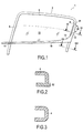
- FIG. 1 is a front view of the seal according to the invention
- FIG. 2 is a cross-section along the line II-II of FIG. 1 ;
- FIG. 3 is a cross-section along the line III-III of FIG. 1 ;
- FIG. 4 is a perspective view of the sealing strip according to the invention.
- FIG. 5 is a perspective view of the sealing strip according to the invention having a flocked lip
- FIG. 6 is a cross-section along the line VI-VI of FIG. 5 ;
- FIG. 7 is an embodiment of a seal according to the prior art.
- the seal 1 consists of a guide slot strip 2 and a sealing strip 10 .
- the guide slot strip 2 consists of three segments forming a continuous whole: a rear upward segment 4 , a horizontal segment 5 and a front upward segment 6 .
- the guide slot strip 2 is encased in the rear, upper and front posts forming the door frame (not depicted) in which the window slides.
- the guide slot strip 2 therefore has substantially a “U”-shaped profile.
- the window 70 is depicted half-way between its open position and its closed position.
- the window 70 When the window 70 is in the closed position (high position), its upper edge comes into contact with the horizontal segment 5 of the guide slot strip, whilst its rear and front edges are respectively in contact over their entire length with the rear upward segment 4 and the front upward segment 6 of the guide slot strip.
- the rear upward segment 4 and the front upward segment 6 of the guide slot strip are linked by the sealing strip 10 .
- the sealing strip is moulded, which makes it possible to give its front part 11 a shape exactly corresponding to the outer surface of the front upward segment 6 of the guide slot strip. A join line between the front part 11 of the sealing strip and the front upward segment 6 of the guide slot strip is therefore no longer necessary.
- the sealing strip 10 bends in order to end with an upward part 12 substantially aligned with the rear upward segment 4 of the guide slot strip.
- the concave edge 13 of the sealing strip at the bend (rear lower corner of the door frame) has a curved shape.
- the upper end of the upward part 12 of the sealing strip 10 is attached to the upward segment 4 of the guide slot strip 2 by a join line 41 .
- the junction between the guide slot strip 2 and the sealing strip 10 comprises a single join line 41 .
- a join line between an extruded material such as the guide slot strip and a moulded material such as the sealing strip according to the invention has the appearance of a ridge. Through the presence of a single join line, the overall aesthetics and strength of the seal 1 according to the invention are therefore improved.
- FIG. 2 is a cross-section of the seal 1 along the line II-II, in the region where the upward part 12 of the sealing strip is superposed on the upward segment 4 of the guide slot strip.
- the upward part 12 of the sealing strip is arranged so as to form a “U” in which the window 70 is intended to slide during its movement between its open position and its closed position. Over the portion where it is superposed on the upward segment 4 of the guide slot strip, the upward part 12 of the sealing strip is therefore substituted for a piece of the upward segment 4 of the guide slot strip which has been removed.
- FIG. 3 is a cross-section of the seal 1 along the line III-III, in the region where the upward part 12 of the sealing strip is not in contact with the upward segment 4 of the guide slot strip.
- the upward segment 4 of the guide slot strip then forms the whole of the “U”-shaped groove in which the window 70 is intended to slide during its movement between its open position and its closed position.
- the removal of a piece of the upward segment 4 of the guide slot strip for which the upward part 12 of the sealing strip is substituted allows optimum encasing of the seal 1 in the door frame.
- FIG. 4 is a perspective view of the sealing strip 10 .
- the sealing strip 10 is produced in a single piece, for example by moulding. In the case of manufacture by moulding, two polymers are bi-injected into the mould in order to obtain in the end a sealing strip comprising a rigid part 14 and a flexible part 16 .
- the rigid part 14 is for example made of rigid plastic and the flexible part made of flexible elastomer.
- the rigid part 14 forms the convex edge of the sealing strip 10
- the flexible part 16 forms the concave edge of the sealing strip 10 .
- the sealing strip 10 is intended to be fixed to the door frame by the rigid part 14 of the sealing strip.
- the rigid part 14 of the sealing strip 10 comprises, on its vertical edge, means 28 of attaching to the rear upward post (not depicted) of the frame ( FIGS. 1 , 4 and 5 ).
- FIG. 5 is another perspective view of the sealing strip, showing the profile intended to be flocked, and fixed to the rigid part 14 of the sealing strip 10 .
- the profile is depicted as having the shape of a lip 20 . This shape of the profile 20 makes it possible to provide better friction between the hairs of the flocking which will be fixed to the profile 20 , and the window 70 , in order to prevent water or other elements entering between the window and the door frame.
- FIG. 6 shows the assembly of the sealing strip 10 and the flocked profile 20 in cross-section.
- the upper portion of the flexible part 16 covers the upper edge of the rigid part 14 .
- the flocked profile 20 is fixed to a vertical portion of the rigid part 14 of the sealing strip 10 , on the opposite side from the edge 30 of the door frame.
- the rigid part 14 of the sealing strip 10 is in its turn fixed to the edge 30 of the door frame.
- a lower portion of the flexible part 16 extends downwards so that the edge 30 of the frame to which the rigid part 14 is intended to be fixed is situated between the lower portion of the rigid part 14 and this lower portion of the flexible part 16 .
- the sealing strip 10 depicted in FIGS. 1 to 6 is depicted solely by way of a non-limiting example.
- the sealing strip 10 could have a different shape, within the limits of the scope of the present invention.
- the concave edge 13 of the sealing strip 10 could form an angle instead of being curved.
- sealing strip 10 has been depicted in some figures provided with a flocked profile 20 . It could alternatively be provided with another slippery coating intended to fulfil the same functions as a flocked profile.
Landscapes
- Engineering & Computer Science (AREA)
- Mechanical Engineering (AREA)
- Manufacturing & Machinery (AREA)
- Seal Device For Vehicle (AREA)
- Specific Sealing Or Ventilating Devices For Doors And Windows (AREA)
- Glass Compositions (AREA)
- Window Of Vehicle (AREA)
Abstract
Description
Claims (22)
Applications Claiming Priority (3)
| Application Number | Priority Date | Filing Date | Title |
|---|---|---|---|
| FR0651807 | 2006-05-18 | ||
| FR0651807A FR2901187B1 (en) | 2006-05-18 | 2006-05-18 | GLASS SEAL WITH MOLDING BRUSH |
| PCT/FR2007/051295 WO2007135329A1 (en) | 2006-05-18 | 2007-05-16 | Window weatherseal with molded weatherstrip |
Publications (2)
| Publication Number | Publication Date |
|---|---|
| US20090265999A1 US20090265999A1 (en) | 2009-10-29 |
| US8429855B2 true US8429855B2 (en) | 2013-04-30 |
Family
ID=37575972
Family Applications (1)
| Application Number | Title | Priority Date | Filing Date |
|---|---|---|---|
| US12/300,825 Active 2027-12-24 US8429855B2 (en) | 2006-05-18 | 2007-05-16 | Window weatherseal with molded weatherstrip |
Country Status (8)
| Country | Link |
|---|---|
| US (1) | US8429855B2 (en) |
| EP (1) | EP2032380B1 (en) |
| CN (1) | CN101466564B (en) |
| AT (1) | ATE473880T1 (en) |
| DE (1) | DE602007007769D1 (en) |
| FR (1) | FR2901187B1 (en) |
| PL (1) | PL2032380T3 (en) |
| WO (1) | WO2007135329A1 (en) |
Cited By (3)
| Publication number | Priority date | Publication date | Assignee | Title |
|---|---|---|---|---|
| USD930536S1 (en) * | 2019-07-12 | 2021-09-14 | Jinhao Guo | Weatherstrip for car door |
| US20220410683A1 (en) * | 2021-06-29 | 2022-12-29 | Kinugawa Rubber Ind. Co., Ltd. | Glass run |
| US12054037B2 (en) * | 2021-10-01 | 2024-08-06 | Hutchinson | Heating seal for a window of a vehicle |
Families Citing this family (9)
| Publication number | Priority date | Publication date | Assignee | Title |
|---|---|---|---|---|
| FR2920112B1 (en) * | 2007-08-24 | 2009-10-30 | Hutchinson Sa | METHOD FOR MANUFACTURING AN UPPER OPENING MODULE FOR GLAZING A VEHICLE, AND SUCH A MODULE |
| EP2230118B1 (en) * | 2009-03-17 | 2012-05-30 | Pilkington Italia S.p.A. | Vehicle glazing having a trim mounted thereon |
| DE102010034340B4 (en) | 2010-08-14 | 2024-05-23 | Volkswagen Aktiengesellschaft | Recyclable window shaft seal |
| FR2975036B1 (en) * | 2011-05-10 | 2013-05-17 | Hutchinson | MULTI-INJECTION MOLD PROFILE FORMING A SEAL OR A BODY FOR MOTOR VEHICLE BODYWORK, AND METHOD FOR MANUFACTURING THE SAME. |
| FR2975348B1 (en) * | 2011-05-20 | 2014-08-15 | Faurecia Interieur Ind | SEAL FOR MOTOR VEHICLE, AUTOMOTIVE VEHICLE STRUCTURE COMPRISING SUCH A SEAL, AND PROCESS FOR PRODUCING THE SAME |
| CN102825461B (en) * | 2012-09-24 | 2014-09-17 | 昆山皇田汽车配件工业有限公司 | Automobile skylight weather strip mistake-proof jig |
| CN107791801B (en) * | 2017-11-16 | 2023-09-22 | 建新赵氏科技股份有限公司 | Integrated variable cross-section external water cutter for rear window of car |
| FR3095989B1 (en) * | 2019-05-16 | 2021-04-23 | Renault Sas | EXTERIOR LICKING WITH EVOLVING TRIM |
| CN114347378B (en) * | 2021-12-31 | 2023-09-26 | 昆山市鸿毅达精密模具有限公司 | Double-color injection molding mold for automobile sealing strip |
Citations (13)
| Publication number | Priority date | Publication date | Assignee | Title |
|---|---|---|---|---|
| US4704820A (en) * | 1985-05-22 | 1987-11-10 | Toyoda Gosei Co., Ltd. | Door glass run for automobiles |
| DE3843057A1 (en) | 1987-12-24 | 1989-07-13 | Toyoda Gosei Kk | GASKET PROFILE BAR |
| EP0422592A2 (en) | 1989-10-11 | 1991-04-17 | METZELER Automotive Profiles GmbH | Clamping sealing joint |
| US5433038A (en) | 1993-12-03 | 1995-07-18 | Gencorp Inc. | Vehicle window weather sealing strip with retaining clip |
| EP0678412A1 (en) | 1994-04-18 | 1995-10-25 | The Standard Products Company | Weatherstrip assembly |
| EP0983891A1 (en) | 1998-09-03 | 2000-03-08 | Hutchinson | Guiding groove for a motor vehicle and its method for positioning, especially by differential bending |
| US20010015035A1 (en) * | 2000-02-21 | 2001-08-23 | Masahiro Nozaki | Trim and glass run attachment structure in vehicle door |
| US6612074B1 (en) * | 1999-05-27 | 2003-09-02 | Schlegel Corporation | Glass run surround cap |
| US6668488B2 (en) * | 2000-08-30 | 2003-12-30 | Toyoda Gosei Co., Ltd. | Glass run for motor vehicle |
| US6681526B2 (en) * | 1996-07-09 | 2004-01-27 | Decoma International Inc. | Integrally formed B-pillar and belt-line window molding including snap-on cover member |
| FR2856331A1 (en) | 2003-06-18 | 2004-12-24 | Hutchinson | Motor vehicle body thermoplastic seal injection moulding procedure uses U-shaped core injected with side at angle that reduces on cooling |
| US6837005B2 (en) * | 2001-09-03 | 2005-01-04 | Nishikawa Rubber Co., Ltd. | Weatherstrip for automobile |
| DE102004059384A1 (en) | 2003-12-09 | 2005-07-14 | Hutchinson | Method for producing a seal, in particular a guide rail for a motor vehicle glazing, and seal produced in this way |
Family Cites Families (1)
| Publication number | Priority date | Publication date | Assignee | Title |
|---|---|---|---|---|
| JPH0773893B2 (en) * | 1993-06-07 | 1995-08-09 | トキワケミカル工業株式会社 | Molding method for automotive weather strip |
-
2006
- 2006-05-18 FR FR0651807A patent/FR2901187B1/en not_active Expired - Fee Related
-
2007
- 2007-05-16 CN CN2007800217172A patent/CN101466564B/en active Active
- 2007-05-16 PL PL07766069T patent/PL2032380T3/en unknown
- 2007-05-16 EP EP07766069A patent/EP2032380B1/en active Active
- 2007-05-16 WO PCT/FR2007/051295 patent/WO2007135329A1/en active Application Filing
- 2007-05-16 US US12/300,825 patent/US8429855B2/en active Active
- 2007-05-16 DE DE602007007769T patent/DE602007007769D1/en active Active
- 2007-05-16 AT AT07766069T patent/ATE473880T1/en not_active IP Right Cessation
Patent Citations (15)
| Publication number | Priority date | Publication date | Assignee | Title |
|---|---|---|---|---|
| US4704820A (en) * | 1985-05-22 | 1987-11-10 | Toyoda Gosei Co., Ltd. | Door glass run for automobiles |
| DE3843057A1 (en) | 1987-12-24 | 1989-07-13 | Toyoda Gosei Kk | GASKET PROFILE BAR |
| US4894954A (en) * | 1987-12-24 | 1990-01-23 | Toyoda Gosei Co., Ltd. | Weather strip for vehicle |
| EP0422592A2 (en) | 1989-10-11 | 1991-04-17 | METZELER Automotive Profiles GmbH | Clamping sealing joint |
| US5433038A (en) | 1993-12-03 | 1995-07-18 | Gencorp Inc. | Vehicle window weather sealing strip with retaining clip |
| US5493814A (en) * | 1994-04-18 | 1996-02-27 | The Standard Products Company | Weatherstrip assembly including a glass run channel and belt weatherstrip with decorative cover |
| EP0678412A1 (en) | 1994-04-18 | 1995-10-25 | The Standard Products Company | Weatherstrip assembly |
| US6681526B2 (en) * | 1996-07-09 | 2004-01-27 | Decoma International Inc. | Integrally formed B-pillar and belt-line window molding including snap-on cover member |
| EP0983891A1 (en) | 1998-09-03 | 2000-03-08 | Hutchinson | Guiding groove for a motor vehicle and its method for positioning, especially by differential bending |
| US6612074B1 (en) * | 1999-05-27 | 2003-09-02 | Schlegel Corporation | Glass run surround cap |
| US20010015035A1 (en) * | 2000-02-21 | 2001-08-23 | Masahiro Nozaki | Trim and glass run attachment structure in vehicle door |
| US6668488B2 (en) * | 2000-08-30 | 2003-12-30 | Toyoda Gosei Co., Ltd. | Glass run for motor vehicle |
| US6837005B2 (en) * | 2001-09-03 | 2005-01-04 | Nishikawa Rubber Co., Ltd. | Weatherstrip for automobile |
| FR2856331A1 (en) | 2003-06-18 | 2004-12-24 | Hutchinson | Motor vehicle body thermoplastic seal injection moulding procedure uses U-shaped core injected with side at angle that reduces on cooling |
| DE102004059384A1 (en) | 2003-12-09 | 2005-07-14 | Hutchinson | Method for producing a seal, in particular a guide rail for a motor vehicle glazing, and seal produced in this way |
Cited By (4)
| Publication number | Priority date | Publication date | Assignee | Title |
|---|---|---|---|---|
| USD930536S1 (en) * | 2019-07-12 | 2021-09-14 | Jinhao Guo | Weatherstrip for car door |
| US20220410683A1 (en) * | 2021-06-29 | 2022-12-29 | Kinugawa Rubber Ind. Co., Ltd. | Glass run |
| US11865901B2 (en) * | 2021-06-29 | 2024-01-09 | Kinugawa Rubber Ind. Co., Ltd. | Glass run |
| US12054037B2 (en) * | 2021-10-01 | 2024-08-06 | Hutchinson | Heating seal for a window of a vehicle |
Also Published As
| Publication number | Publication date |
|---|---|
| EP2032380B1 (en) | 2010-07-14 |
| US20090265999A1 (en) | 2009-10-29 |
| CN101466564A (en) | 2009-06-24 |
| EP2032380A1 (en) | 2009-03-11 |
| DE602007007769D1 (en) | 2010-08-26 |
| FR2901187B1 (en) | 2015-09-25 |
| ATE473880T1 (en) | 2010-07-15 |
| WO2007135329A1 (en) | 2007-11-29 |
| CN101466564B (en) | 2013-05-15 |
| PL2032380T3 (en) | 2011-01-31 |
| FR2901187A1 (en) | 2007-11-23 |
Similar Documents
| Publication | Publication Date | Title |
|---|---|---|
| US8429855B2 (en) | Window weatherseal with molded weatherstrip | |
| CN103009974B (en) | Glass Run | |
| EP3623191A1 (en) | Encapsulated fixed window module for a motor vehicle | |
| CN102442185B (en) | Glass run for motor vehicle | |
| US8166708B2 (en) | Integrated glass run and upper reveal with film | |
| US20150101254A1 (en) | Sealing system for movable window of rear window assembly | |
| PL183617B1 (en) | Mounted window glass panel assembly for motor vehicles and method of making such assembly | |
| JP5572536B2 (en) | Glass run | |
| CN211808991U (en) | Vehicle decoration, forming device and vehicle window assembly | |
| CN107054022A (en) | Car door | |
| US11338659B2 (en) | Method of making a weather strip and bright strip assembly for a vehicle door | |
| EP1567382B1 (en) | Window sealing and guiding arrangements | |
| US20170267086A1 (en) | Automobile back-door structure | |
| CN210309875U (en) | Door angle window and glass guide rail assembly structure and vehicle | |
| DE102011118897B4 (en) | glass run | |
| JP3726658B2 (en) | Molding method for composite parts | |
| KR200351265Y1 (en) | Sunvisor for automobile | |
| JPH05178097A (en) | Weatherstrip molding for vehicle and its manufacturing method | |
| US20210309086A1 (en) | Molded outer belt weatherstrip | |
| JP4329033B2 (en) | Automotive glass run | |
| JPH08300953A (en) | Door glass run structure of automobile | |
| CN117901624A (en) | Encapsulated fixed window module for a motor vehicle and motor vehicle | |
| JP2008030633A (en) | Outer weather strip | |
| KR20090005426A (en) | Door belt molding for automobile and method for manufacturing the same | |
| JP2019123401A (en) | Belt line molding |
Legal Events
| Date | Code | Title | Description |
|---|---|---|---|
| AS | Assignment |
Owner name: COOPER-STANDARD AUTOMOTIVE FRANCE, S.A., FRANCE Free format text: ASSIGNMENT OF ASSIGNORS INTEREST;ASSIGNOR:STEFANELLI, DIDIER;REEL/FRAME:022050/0560 Effective date: 20081125 |
|
| AS | Assignment |
Owner name: COOPER-STANDARD AUTOMOTIVE FRANCE S.A., FRANCE Free format text: CORRECTIVE ASSIGNMENT TO CORRECT THE CITY OF THE ASSIGNEE PREVIOUSLY RECORDED ON REEL 022050 FRAME 0560;ASSIGNOR:STEFANELLI, DIDIER;REEL/FRAME:022085/0612 Effective date: 20081125 Owner name: COOPER-STANDARD AUTOMOTIVE FRANCE S.A., FRANCE Free format text: CORRECTIVE ASSIGNMENT TO CORRECT THE CITY OF THE ASSIGNEE PREVIOUSLY RECORDED ON REEL 022050 FRAME 0560. ASSIGNOR(S) HEREBY CONFIRMS THE FROM: ARGENTEULL TO: ARGENTEUIL;ASSIGNOR:STEFANELLI, DIDIER;REEL/FRAME:022085/0612 Effective date: 20081125 |
|
| STCF | Information on status: patent grant |
Free format text: PATENTED CASE |
|
| CC | Certificate of correction | ||
| FPAY | Fee payment |
Year of fee payment: 4 |
|
| MAFP | Maintenance fee payment |
Free format text: PAYMENT OF MAINTENANCE FEE, 8TH YEAR, LARGE ENTITY (ORIGINAL EVENT CODE: M1552); ENTITY STATUS OF PATENT OWNER: LARGE ENTITY Year of fee payment: 8 |
|
| AS | Assignment |
Owner name: U.S. BANK TRUST COMPANY, NATIONAL ASSOCIATION, AS COLLATERAL AGENT, MICHIGAN Free format text: PATENT SECURITY AGREEMENT (3RD LIEN);ASSIGNORS:COOPER-STANDARD AUTOMOTIVE INC.;COOPER-STANDARD INDUSTRIAL AND SPECIALTY GROUP, LLC;REEL/FRAME:062545/0715 Effective date: 20230127 Owner name: U.S. BANK TRUST COMPANY, NATIONAL ASSOCIATION, AS COLLATERAL AGENT, MICHIGAN Free format text: PATENT SECURITY AGREEMENT (1ST LIEN);ASSIGNORS:COOPER-STANDARD AUTOMOTIVE INC.;COOPER-STANDARD INDUSTRIAL AND SPECIALTY GROUP, LLC;REEL/FRAME:062544/0357 Effective date: 20230127 |