US8421386B2 - Control apparatus for multi-phase rotary machine - Google Patents
Control apparatus for multi-phase rotary machine Download PDFInfo
- Publication number
- US8421386B2 US8421386B2 US13/004,289 US201113004289A US8421386B2 US 8421386 B2 US8421386 B2 US 8421386B2 US 201113004289 A US201113004289 A US 201113004289A US 8421386 B2 US8421386 B2 US 8421386B2
- Authority
- US
- United States
- Prior art keywords
- vector
- voltage
- control
- values
- candidate
- Prior art date
- Legal status (The legal status is an assumption and is not a legal conclusion. Google has not performed a legal analysis and makes no representation as to the accuracy of the status listed.)
- Expired - Fee Related, expires
Links
- 238000004364 calculation method Methods 0.000 claims abstract description 19
- 239000013598 vector Substances 0.000 claims description 254
- 238000011156 evaluation Methods 0.000 claims description 38
- 230000008859 change Effects 0.000 claims description 6
- 238000013178 mathematical model Methods 0.000 claims description 6
- 230000000737 periodic effect Effects 0.000 claims description 3
- 230000004907 flux Effects 0.000 description 22
- 238000010586 diagram Methods 0.000 description 16
- 238000000034 method Methods 0.000 description 11
- 230000007704 transition Effects 0.000 description 8
- 230000001360 synchronised effect Effects 0.000 description 7
- 239000003990 capacitor Substances 0.000 description 5
- 238000009499 grossing Methods 0.000 description 5
- 238000004804 winding Methods 0.000 description 5
- XEEYBQQBJWHFJM-UHFFFAOYSA-N Iron Chemical compound [Fe] XEEYBQQBJWHFJM-UHFFFAOYSA-N 0.000 description 4
- 238000001514 detection method Methods 0.000 description 4
- 238000009434 installation Methods 0.000 description 4
- 230000006698 induction Effects 0.000 description 3
- 230000000694 effects Effects 0.000 description 2
- 229910052742 iron Inorganic materials 0.000 description 2
- 238000006243 chemical reaction Methods 0.000 description 1
- 238000012986 modification Methods 0.000 description 1
- 230000004048 modification Effects 0.000 description 1
- 230000002441 reversible effect Effects 0.000 description 1
Images

Classifications
-
- H—ELECTRICITY
- H02—GENERATION; CONVERSION OR DISTRIBUTION OF ELECTRIC POWER
- H02P—CONTROL OR REGULATION OF ELECTRIC MOTORS, ELECTRIC GENERATORS OR DYNAMO-ELECTRIC CONVERTERS; CONTROLLING TRANSFORMERS, REACTORS OR CHOKE COILS
- H02P23/00—Arrangements or methods for the control of AC motors characterised by a control method other than vector control
- H02P23/14—Estimation or adaptation of motor parameters, e.g. rotor time constant, flux, speed, current or voltage
-
- H—ELECTRICITY
- H02—GENERATION; CONVERSION OR DISTRIBUTION OF ELECTRIC POWER
- H02P—CONTROL OR REGULATION OF ELECTRIC MOTORS, ELECTRIC GENERATORS OR DYNAMO-ELECTRIC CONVERTERS; CONTROLLING TRANSFORMERS, REACTORS OR CHOKE COILS
- H02P21/00—Arrangements or methods for the control of electric machines by vector control, e.g. by control of field orientation
- H02P21/14—Estimation or adaptation of machine parameters, e.g. flux, current or voltage
- H02P21/20—Estimation of torque
-
- H—ELECTRICITY
- H02—GENERATION; CONVERSION OR DISTRIBUTION OF ELECTRIC POWER
- H02P—CONTROL OR REGULATION OF ELECTRIC MOTORS, ELECTRIC GENERATORS OR DYNAMO-ELECTRIC CONVERTERS; CONTROLLING TRANSFORMERS, REACTORS OR CHOKE COILS
- H02P21/00—Arrangements or methods for the control of electric machines by vector control, e.g. by control of field orientation
- H02P21/22—Current control, e.g. using a current control loop
-
- H—ELECTRICITY
- H02—GENERATION; CONVERSION OR DISTRIBUTION OF ELECTRIC POWER
- H02P—CONTROL OR REGULATION OF ELECTRIC MOTORS, ELECTRIC GENERATORS OR DYNAMO-ELECTRIC CONVERTERS; CONTROLLING TRANSFORMERS, REACTORS OR CHOKE COILS
- H02P2207/00—Indexing scheme relating to controlling arrangements characterised by the type of motor
- H02P2207/05—Synchronous machines, e.g. with permanent magnets or DC excitation
Definitions
- the present invention relates to a control apparatus for controlling a control quantity of a polyphase rotary machine, by controlling an inverter (electric power converter circuit) having switching elements connected to the phases of the rotary machine, the switching elements being operated to selectively connect each of the phases to at least two different DC voltage levels.
- an inverter electric power converter circuit
- the inverter can apply three different voltage levels (+v, 0, ⁇ v) to each of the 3 phases of the rotary machine, i.e., there is a total of 27 (3 3 ) operation states of the inverter.
- a plurality of sequences of operation states can extend from each operation state, by respective paths.
- N a predetermined number of future timings, i.e., over a time range k, (k+1), . . . (k+N ⁇ 1) (where N ⁇ 1).
- a mathematical model of the rotary machine is applied to calculate corresponding predicted values of torque developed by the rotary machine.
- Each locus of such predicted values is referred to as a trajectory, i.e., a corresponding trajectory of predicted torque values is obtained for each of the possible operation state sequences that extend from the present timing.
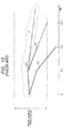
- FIG. 13 of the drawings of the present application illustrate this, for the case of two possible torque trajectories T 1 and T 2 extending from the timing k, with a trajectory T 3 branching from the trajectory T 1 at the timing (k+1).
- the operation state to be established at that timing (k+1) is determined as follows.
- the time range of the prediction calculations extends to the timing (k+2) in this example.
- the trajectory T 3 is predicted to depart from a predetermined range of torque values before the timing (k+2) is reached.
- the trajectory T 2 is extrapolated, it is predicted to depart from the predetermined torque range at approximately the timing (k+3), while the T 1 (extrapolated) is predicted to remain within the predetermined torque range for a longer time.
- Each of these trajectories is then examined to find the total number of successive operation state transitions until the trajectory is predicted to depart from the predetermined torque range (for example, one transition in the case of the trajectory T 3 , two transitions for trajectory T 2 ).
- the total number of switching element (on or off) operations required to effect these transitions is then calculated, for each of the trajectories.
- An evaluation coefficient is then calculated, for each trajectory, by dividing the corresponding total number of switching element operations by the corresponding total number of operation state transitions.
- the trajectory having the smallest value of evaluation coefficient i.e., the lowest frequency of switching element changeovers
- the operation state which is next in the operation state sequence of that optimum trajectory is selected, to be set as the next operation state. For example if the trajectory T 2 in the above example were judged (at timing k) to be optimum, then the operation state indicated as OS 1 would be set as the actual operation state of the inverter at timing (k+1).
- the above processing is repeated at each of successive time steps.
- the switching frequency of the inverter can thereby be limited.
- a control apparatus includes prediction circuitry, configured for predicting future values of a control quantity of the polyphase rotary machine based on respective assumed operation states of the electric power converter circuit, where the operation states correspond to respective combinations of switched statuses (i.e., combinations of connections to respective voltage levels, with the combinations corresponding to respective voltage vectors applied to the rotary machine).
- the control apparatus also includes operation control circuitry, configured for determining a future operation state that is to be established for the electric power converter circuit, with the determination based upon predicted values of the control quantity.
- the control apparatus is characterized in that the operation control circuitry is configured to determine the future operation state such that a specific changeover requirement is satisfied. This is a requirement that no more than one of the phases of the rotary machine will undergoes a change in connection condition (that is, will become connected to a changed voltage level) when a changeover occurs from the present operation state of the power converter circuit to the future operation state.
- control apparatus An updated operating state of the inverter is determined for each of successive intervals referred to as control periods. Prior to changeover to a future operating state (to be set during a future control period) the value of a control quantity that will be attained by the end of that future control period is predicted, for each of a plurality of candidate operating states (i.e., candidate voltage vectors). Each of the candidates must satisfy the above-defined specific changeover requirement.
- the control quantity may for example be a current vector, magnetic flux vector, or torque value of the rotary machine, or a combination of such quantities.
- the prediction is performed by iteratively applying discrete-time difference equations for a prediction interval whose duration is equal to the control period duration, based on a mathematical model of the rotary machine, utilizing detected values of the control quantity and of operating parameters (including the electrical angular velocity) of the rotary machine in the calculations.
- the candidate for which the corresponding predicted control quantity value is evaluated to be closest to a required value of the control quantity (as judged based on absolute values of parameters) is then selected.
- the selected candidate is thereafter set as the operation state of the power converter circuit during the specified future control period, i.e., is set as the voltage vector that is applied to the phase windings of the rotary machine by the power converter circuit during that period.
- forward sequence signifies a sequence of operation states which corresponds to the direction in which the rotor of the polyphase rotary machine is rotating.
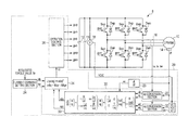
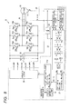
- FIG. 1 shows a system diagram of a first embodiment of a control apparatus, for controlling the value of torque produced by an IPMSM;
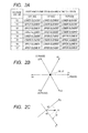
- FIGS. 2A , 2 B and 2 C are diagrams for describing operation states of an inverter of the first embodiment
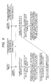
- FIG. 3 is a timing diagram showing an example of relationships between forms of changeover of operation state of the inverter and resultant voltage surge amplitudes
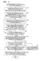
- FIG. 4 is a flow diagram of a processing sequence performed during a control period by employing model predictive calculations, for selecting an updated operation state of the inverter, to be applied for the succeeding control period;
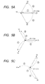
- FIGS. 5A , 5 B, 5 C are diagrams illustrating a method of voltage vector selection, used with the first embodiment
- FIGS. 6A , 6 B, 6 C are diagrams showing results obtained for the first embodiment
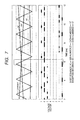
- FIG. 7 is a timing diagram illustrating transitions of switching conditions, for triangular-wave PWM control
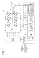
- FIG. 8 shows a system diagram of a second embodiment of a control apparatus
- FIG. 9 is a conceptual diagram for illustrating timing relationships of processing operations executed by the first embodiment
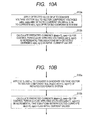
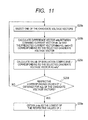
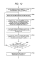
- FIGS. 10A , 10 B, 11 and 12 are flow diagrams for illustrating processing contents of steps of the flow diagram of FIG. 4 ;
- FIG. 13 is a conceptual diagram for use in describing a prior art example of a control apparatus for a polyphase rotary machine.
- a first embodiment is a control apparatus for an inverter (electrical power converter apparatus) which drives an IPMSM (Interior Permanent Magnet Synchronous Motor), intended for installation in a hybrid motor vehicle.
- FIG. 1 shows the overall configuration of the embodiment, connected to a motor-generator 10 and to an inverter 8 which drives the motor-generator 10 and is controlled by a control apparatus 20 .
- the motor-generator 10 is a 3-phase IPMSM, with the operation as a synchronous induction motor being described in the following.
- control apparatus 20 is described as a set of interconnected system sections in the following, however it will be understood that in practice the described functions of these sections are performed by circuitry based on a usual type of microcomputer having a CPU, ROM, RAM, etc., which executes a stored program.
- a high-voltage battery 12 is connected to supply a DC operating voltage to the inverter 8 , with a smoothing capacitor 13 being connected between the output terminals of the high-voltage battery 12 .
- the inverter 8 is formed of three series-connected pairs of switching elements as shown, i.e., the pair Sup, Sun, the pair Svp, Svn, and the pair Swp, Swn. The junction points of the pair Sup, Sun, the pair Svp, Svn, and the pair Swp, Swn are respectively connected to the U, V and W phase terminals of the motor-generator 10 .
- each of the switching elements Sup, Sun, Svp, Svn, Swp and Swn is an IGBT (Insulated Gate Bipolar Transistor).
- Diodes Dup, Dun, Dvp, Dvn, Dwp, Dwn are respectively connected in parallel with the switching elements Sup, Sun, Svp, Svn, Swp and Swn, in reverse direction to the direction of forward current flow through the switching elements.
- the angular position of the rotor of the motor-generator 10 is detected by a rotation angle sensor 14 , to obtain the rotor electrical angle (referred to in the following simply as the electrical angle) ⁇ .
- a current sensor 16 detects the respective values of current iu, iv, iw of the phases U, V, W of the motor-generator 10 .
- a voltage sensor 18 detects the input voltage (power source voltage) VDC of the inverter 8 .
- the detection values obtained by these sensors are acquired via an interface ((not shown in the drawings) by the control apparatus 20 , which operates as a low-voltage system. Based on the detection values from the sensors, the control apparatus 20 generates operation signals for determining the operation state of the inverter 8 , i.e., operation signals gup, gun, gyp, gvn, gwp, gwn, respectively applied to the control electrodes of the switching elements Sup, Sun, Svp, Svn, Swp and Swn.
- operation signals gup, gun, gyp, gvn, gwp, gwn respectively applied to the control electrodes of the switching elements Sup, Sun, Svp, Svn, Swp and Swn.
- the control apparatus 20 controls the inverter 8 to maintain the level of torque generated by the motor-generator 10 close to a request torque value Tr.
- the inverter 8 is controlled to supply respective values of current to the phases of the motor-generator 10 in accordance with a command current vector (idr, iqr), calculated in accordance with the request value of torque Tr.
- a command current vector idr, iqr
- the values of current which will flow in the motor-generator 10 for respectively different ones of a plurality of operating conditions of the inverter 8 are predicted by utilizing model predictive control.
- the next operation state of the inverter 8 is selected as the operation state that is predicted to result in an actual current vector which is close to the command current vector, as evaluated based on an evaluation coefficient as described hereinafter, while also ensuring that each time the operation state of the inverter is updated, no more than one of the phases of the motor-generator 10 will become connected to a changed voltage level.
- the dq converter 22 Based on the electrical angle ⁇ which is detected by the rotation angle sensor 14 , the dq converter 22 converts the phase current values iu, iv, iw detected by the current sensor 16 to a vector (id, iq) of a d, q 2-axis coordinate system which rotates with the rotor of the motor-generator 10 .
- the detected set of iu, iv, iw current values are first converted to a vector expressed in a stationary 2-axis coordinate system, which is then rotated through an angle equal to the detected electrical angle ⁇ , and the components (id, iq) of the vector (actual current vector) are obtained with respect to the rotated coordinates. Since the calculations for performing these operations are well documented, description is omitted.
- Periodically detected values of the electrical angle ⁇ are also inputted to the speed calculation section 23 , which thereby calculates the electrical angular velocity ⁇ .
- the aforementioned command current vector (idr, iqr), the actual current vector (id, iq), and electrical angular velocity ⁇ are each inputted to a model predictive control section 30 of the control apparatus 20 , together with a voltage vector (vd, vq) described hereinafter.
- the model predictive control section 30 determines a voltage vector Vi expressing the operation state of the inverter 8 (i.e., specific combination of states of the switching elements) which is to be established at the next updating timing, and inputs information expressing the voltage vector Vi to the operation control section 26 .
- the operation control section 26 At the next updating timing, the operation control section 26 generates operation signals for controlling the switching elements of the inverter 8 to set the operation state that corresponds to the voltage vector Vi (i.e., so that the combination of voltage levels expressed by the voltage vector Vi becomes applied to the phase windings of the rotary machine 10 ) and supplies these operation signals to the inverter 8 .
- the inverter 8 has eight possible operation states (8 possible combinations of connection states of the phases of the motor-generator 10 ) as shown by the table of FIG. 2A .
- each of the operation states can be expressed as a combination of three (u, v, w) values, each of which is either VDC/2 (corresponding to a high-voltage side switching element being set ON) or ⁇ VDC/2 (corresponding to a low-voltage side switching element being set ON).
- the eight operation states thus correspond to respective vectors V 0 to V 7 , as indicated in FIG. 2A .
- the voltage vector V 0 is expressed as ( ⁇ VDC/2, ⁇ VDC/2, ⁇ VDC/2), and similarly, the voltage vector V 1 is expressed as (VDC/2, ⁇ VDC/2, ⁇ VDC/2).
- the voltage vector V 0 corresponds to the operation state in which each of the low-voltage side switching elements Sun, Svn, Swn is ON
- the voltage vector V 7 corresponds to the operation state in which each of the high-voltage side switching elements Sup, Svp, Swp is ON.
- each of the vectors V 0 and is V 7 (referred to as the zero vectors) corresponds to an operation state in which there is zero voltage between each of the pairs of phases of the motor-generator 10 .
- the remaining six voltage vectors V 1 to V 6 each correspond to a switching mode in which at least one high-voltage side switching element and at least one low-voltage side switching element is in the ON state
- the voltage vectors V 1 , V 3 and V 5 correspond to operation states in which only the U, V and W phases respectively are connected to the positive side of the supply voltage VDC.
- Each of the voltage vectors V 0 to V 7 can be expressed as a vector in a stationary 2-axis coordinate system, as shown in FIG. 2B .
- the prediction processing executed by the model predictive control section 30 will be described in the following.
- the specified vector (expressed in a stationary 2-axis coordinate system as illustrated in FIG. 2B ) is supplied by the operation state setting section 31 to the dq conversion section 32 .
- the coordinate system is then rotated by an amount equal to the detected electrical angle, and the components vd, vq of the voltage vector are then obtained with respect to the rotated dq coordinate system, and inputted to the prediction section 33 . This is illustrated by FIG. 2C , for the case of the voltage vector V 1 .
- the model predictive control section 30 calculates a predicted current vector for a prediction interval (i.e., a current vector which is predicted to be attained by the end of that interval). Specifically, the prediction interval is treated as a succession of discrete time-steps.
- the component values of the actual current vector (id, iq) are used as initial values (i.e., for calculating the predicted current vector that which will be reached by the end of the first time-step).
- the prediction calculations are based on equations (c3), (c4) below, for obtaining the predicted rate of change of current in each of successive time-steps, and thereby calculate the predicted value of current attained at the end of a prediction interval (succession of time-steps) by iterative calculations applying discrete-time difference equations over the prediction interval.
- the equations (c3), (c4) are obtained by differentiating the current terms in the voltage equations (c1), (c2) below, which are derived based on a model of the motor-generator 10 , and express relationships between the voltage vector components vd and vq applied to the motor-generator 10 and the d-axis and q-axis inductance values Ld, Lq of the stator windings, the stator winding equivalent resistance R, the rate of change ⁇ of the electrical angle ⁇ (i.e., rotational angular velocity), and the magnetic flux linkage constant ⁇ of the rotor, with p denoting the differential operator (derivative with respect to time).
- vd ( R+pLd ) ⁇ id ⁇ Lq ⁇ iq (c1)
- vq ⁇ Ld ⁇ id ⁇ ( R+pLq ) iq+ ⁇
- pid ⁇ ( R/Ld ) ⁇ id + ⁇ ( Lq/Ld ) ⁇ iq+vd/Ld (c3)
- piq ⁇ ( Ld/Lq ) ⁇ id ⁇ ( Rd/Lq ) ⁇ iq+vq/Lq ⁇ /Lq (c4)
- the prediction calculations are performed for each of a plurality of operation states of the inverter 8 , expressed by corresponding ones of a sub-group of the voltage vectors V 1 ⁇ V 0 , i.e., voltage vectors which have been selected as candidates to be applied in a succeeding control period, as described hereinafter.
- the current vector (ide, iqe) is inputted to the operation state determining section 34 together with the command current vector (idr, iqr).
- Each of the predicted current vectors (ide, iqe) is evaluated with respect to the command current vector (idr, iqr), to derive an evaluation coefficient J, which is assigned to the corresponding candidate voltage vector.
- the voltage vector having the lowest value of J is then selected, to be applied in the next control period.
- the evaluation coefficient J is calculated as the square of the modulus of the difference vector between the command current vector (idr, iqr) and the predicted current vector (ide, iqe), so that the evaluation coefficient is obtained as a scalar absolute value.
- Each of the vector components idr, iqr, ide, iqe may take a positive or negative value.
- each interval between successive updating timings is referred to as a control period, of duration Tc.
- an updating timing (n) is followed by a control period (n), in which the operation state of the inverter 8 is held in accordance with a previously determined one of the voltage vectors V 0 to V 7 .
- the voltage vector V(n+1) that is to be set for the succeeding control period (n+1) is determined at the updating timing (n).
- step S 10 The processing of FIG. 4 , executed at an updating timing (n), is as follows. Firstly (step S 10 ), the electrical angle ⁇ (n) and the actual current vector (id(n), iq(n)) of the motor-generator 10 at that point in time are each detected, and information specifying the voltage vector V(n) (one of the voltage vectors V 0 ⁇ V 7 , which was determined in the preceding execution of this processing routine) is acquired. The inverter 8 is then set in the operation state corresponding to that voltage vector, by operation signals applied to the switching elements of the inverter 8 . The currently derived electrical angular velocity ⁇ is also acquired.
- the d,q components vd(n), vq(n) of the voltage vector V(n) are also derived, based on the detected electrical angle ⁇ as described above.
- step S 12 the components ide(n+1), iqe(n+1) of a predicted current vector are calculated, i.e., the current vector which is predicted to be attained by the end of the control period (n). This is performed using discrete-time difference equations in conjunction with equations (c3), (c4) as described above, with the prediction interval being the duration of a control period, and with the actual (detected) current values id(n), iq(n) from step S 10 being respective initial values of current for the difference equation calculations.
- FIG. 10A These processing contents of step S 12 are illustrated in FIG. 10A .
- step S 14 a plurality of repetitions of a sequence of steps S 14 to S 18 is performed.
- one of a plurality of candidate voltage vectors (one of V 0 ⁇ V 7 ) is selected.
- Each of these is a candidate for the voltage vector V(n+1), to be applied in the succeeding control period (n+1).
- Each candidate voltage vector must satisfy the above-described condition that the transition from the voltage vector V(n) of the control period (n) to the voltage vector V(n+1) at the start of the next control period does not result in more than one of the phases of the motor-generator 10 being switched to a different voltage level.
- V(n) is the zero vector V 0
- there are again four candidate voltage vectors i.e., the odd-numbered vectors V 1 , V 3 and V 5 , and the zero vector V 0
- the candidate voltage vectors are the even-numbered voltage vectors V 2 , V 4 or V 6 , and the zero vector V 7 .
- step S 16 is executed in which a corresponding predicted current vector (ide(n+2), iqe(n+2)) is calculated.
- This is a current vector which is predicted to be attained at the updating timing (n+2) (by the end of the next control period (n+1)) if that candidate voltage vector were to be applied for the control period (n+1).
- This prediction calculation is performed as described for step S 12 above, executed for a prediction interval having a duration equal to the control period duration.
- the predicted current values ide(n+1), iqe(n) from step S 10 are used as initial values, together with adjusted d,q values vd(n+1),vq(n+1) of the voltage vector V(n).
- step S 16 These contents of step S 16 are illustrated in step FIG. 10B .
- step S 16 A d,q component values vd(n+1),vq(n+1) of the candidate voltage vector are obtained by applying an electrical angle ( ⁇ + ⁇ Tc) to rotate the d,q axes.
- ⁇ is the electrical angle variation speed which was acquired in step S 10
- ⁇ is the electrical angle value which was detected in step S 10 .
- a predicted current vector ide(n+2),iqe(n+2) corresponding to this candidate voltage vector is then calculated (step S 16 B), by applying the voltage vector vd(n+1),vq(n+1) in discrete-time difference equations as described above, using the predicted current vector components ide(n+1), iqe(n) as initial values of current in the calculations.
- step S 18 a decision is made (step S 18 ) as to whether predicted current vectors have been derived corresponding to all of the candidate voltage vectors. If not, operation returns to step S 14 , while if there is a YES decision, step S 20 is then executed.
- step S 20 for each of the candidate voltage vectors, the corresponding predicted current vector ide(n+2),iqe(n+2) is evaluated.
- the vector ide(n+2),iqe(n+2) is designated as (ide, iqe).
- the vector difference between each predicted current vector (ide, iqe) and the command current vector (idr, iqr) is derived, then the square of the modulus of the difference vector is calculated, to obtain an evaluation coefficient J as a (scalar) absolute value. The lowest value Jmin that has been obtained for J is then determined.
- step S 20 The processing contents of step S 20 are illustrated in FIG. 11 .
- Step S 22 is then executed, to judge whether a plurality of candidate voltage vectors each correspond to the lowest evaluation coefficient Jmin. If only a single candidate voltage vector corresponds to that lowest value, step S 26 is executed, to select that candidate voltage vector to become the next voltage vector V(n+1).
- step S 24 is executed, in which the one out of that plurality of candidate voltage vectors which is next in a forward sequence is selected, to become the next voltage vector V(n+1).
- forward sequence of the voltage vectors V 0 ⁇ V 7 , at any particular time, signifies the sequence which corresponds to the direction in which the rotor of the rotary machine is rotating at that time (that rotation direction being referred to in the following as the “forward direction” for simplicity). If the rotation direction is not permanently fixed, then a rotation detection sensor, etc., may be used to detect the direction of rotation, and thereby determine whether the voltage vector sequence V 0 , V 1 , V 2 , . . . or the sequence V 0 , V 7 , V 6 , . . . currently is the “forward sequence”.
- V 2 and V 1 are candidate voltage vectors which each have the lowest evaluation coefficient Jmin, vector V 2 would be selected in step S 24 .
- step S 24 may be executed such that if the plurality of candidate voltage vectors having the same lowest value of evaluation coefficient include both a zero vector and non-zero vectors, then the voltage vector V(n+1) is set as the zero vector. This can reduce the number of selection branches (number of candidate voltage vectors), when the processing of steps S 14 to S 22 is subsequently again performed.
- step S 28 is executed in which the selected candidate voltage vector is designated as the one of the voltage vectors V 0 ⁇ V 1 which is to be applied in the next control period.
- the operation state of the inverter 8 for the next control period (n+1) is determined by processing executed in the present control period (n), based on prediction calculation applying a mathematical model of the motor-generator 10 .
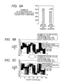
- FIG. 6A shows graphs of experimental results (number of switching operations) obtained before and after applying the processing of the above embodiment in controlling an IPMSM.
- FIGS. 6B , 6 C are corresponding waveform diagrams, corresponding to FIG. 6A , showing time-axis variations in the voltage vectors, obtained before and after applying the processing of the above embodiment.
- “before” signifies that the voltage vector to be set as the next voltage vector V(n+1)) is selected from all of the voltage vectors V 0 ⁇ V 7 , without applying the above-described limitation for selecting the candidate voltage vectors.
- the invention enables the frequency of switching operations by the switching elements of the inverter to be substantially reduced, while at the same time ensuring that simultaneous switching of a plurality of phases is prevented, so that the amplitude of voltage surges can be reduced.
- the voltage vector which is next in the above-defined forward sequence is selected. This serves to reduce the number of changeovers of the switching elements that occur within each electrical angle period, by reducing a tendency for the successively selected voltage vectors to vary irregularly.
- FIG. 8 A second embodiment of a control apparatus for an inverter of a IPMSM will be described in the following referring to FIG. 8 . Only points of difference between this embodiment and the first embodiment of FIG. 1 will be described in detail, and components of the second embodiment which correspond to components of the first embodiment are designated by identical reference numerals to those of FIG. 1 .
- the second embodiment essentially differs from the first embodiment in that the direct control quantities (quantities whose values are predicted for use in evaluation processing for determining the next operation state of the inverter) are torque and magnet flux.
- the predicted current vector values ide(n+2), iqe(n+2) for the control period (n+1) following the control period (n) are derived as described above for the first embodiment.
- this predicted current vector is then converted by a torque/magnetic flux determining section 37 to a corresponding combination of predicted torque Te and predicted magnetic flux vector ⁇ e (i.e., ⁇ de, ⁇ qe).
- Equation (c7) P denotes the number of pole pairs of the motor-generator 10 .
- the request value of torque Tr is inputted to the 38 , which outputs a corresponding command value of magnetic flux vector ⁇ r.
- Each value of ⁇ r stored in the torque/magnetic flux map 38 may for example be derived as the magnetic flux vector which is estimated to provide a corresponding requested torque value while requiring a minimum amount of current.
- the operating state determining section 34 a of this embodiment has a similar function to the operation state determining section 34 of the first embodiment, i.e., to determine (during the current control period) the one of the voltage vectors V 0 ⁇ V 7 which is to be set for the succeeding control period, with the determination made based upon an evaluation coefficient J.
- the processing contents of step S 20 in the flow diagram of FIG. 4 for obtaining the evaluation coefficient J, are illustrated in the flow diagram of FIG. 12 .
- the difference vector E ⁇ between the command magnetic flux vector ⁇ r and the predicted magnetic flux vector ⁇ e is obtained, and the square of E ⁇ (i.e., square of the modulus) is calculated.
- the difference ET between the request value of torque Tr and the predicted torque value Te is calculated, and the square of that difference ET is obtained.
- the square of the difference vector E ⁇ is multiplied by a weighting value ⁇ , while the square of the difference ET is multiplied by a weighting value ⁇ ( ⁇ , ⁇ 0, ⁇ 0) and the multiplication results are summed, to obtain the evaluation coefficient J.
- the weighting coefficients ⁇ and ⁇ are predetermined such to establish an appropriate relationship between the squared torque and magnetic flux values. That is to say, if the units used to measure torque are such that the numeric value of torque is excessively high, then the contribution of the torque term to the evaluation coefficient J will be excessively large.
- the relative contributions of the magnetic flux term ( ⁇ ET 2 ) and the torque term ( ⁇ E ⁇ 2 ) to the value of J can be adjusted appropriately, by suitably determining the values of ⁇ and ⁇ .
- control of magnetic flux (by selecting respective voltage vectors V 0 ⁇ V 7 based on the evaluation results) can be adjusted as required by appropriately adjusting the weighting coefficients ⁇ and ⁇ .
- the operation state of the inverter 8 for the next control period (n+1) is determined during the present control period based on a combination of a torque value and magnetic flux vector which are predicted to be respectively attained by the end of the next control period. That is, a predicted combination of torque value and magnetic flux vector is calculated for each of the candidate voltage vectors, and evaluation is performed based on that combination. In other respects the operation is similar to that of the first embodiment.
- step S 26 of FIG. 4 when a single candidate voltage vector is found to correspond to the lowest value of evaluation coefficient (Jmin), then that candidate voltage vector is selected to become V(n+1), i.e., to determine the operation state of the inverter in the next control period.
- Jmin evaluation coefficient
- An alternative method of selection is as follows. The remaining candidate voltage vectors (i.e., which each correspond to an evaluation coefficient value higher than Jmin) are examined.
- V 3 will be selected to become the next voltage vector (V(n+1)), even if the vector V 2 corresponds to the lowest evaluation coefficient value Jmin.
- any voltage vector (one of V( 0 ) ⁇ V( 7 )) which differs from the present voltage vector V(n) by no more than one phase state changeover can be selected as a candidate for becoming the voltage vector that will be applied in the next control period.
- a voltage vector can be selected as a candidate voltage vector only if it is next in the forward sequence of the voltage vectors or is the present voltage vector.
- the control quantity (with the first embodiment, stator current vector) which will be attained at the next-but-one updating timing is predicted for each candidate voltage vector.
- the current vector (ide(n+2),iqe(n+2) is predicted at the updating timing (n), i.e., the control quantity values predicted to be attained at the updating timing (n+2), that is, attained by the end of the control period (n+1) which succeeds the present control period (n).
- the control quantity value that will be attained after a plurality of control periods which will succeed the present control period.
- phase current values (iu, iv, iw) are detected, to obtain id(n), iq(n), at each of the updating timings.
- these values of current at other timings, e.g., midway within each control period.
- predicted values of current would be used as initial values in the calculation (i.e. predicted values which had been calculated using detected values of current as initial values, with the detection having been performed midway through the preceding control period (n ⁇ 1)).
- the electrical angle ⁇ is detected at each of the updating timings.
- an estimated value of ⁇ could be utilized instead of a currently detected value.
- the estimated value of ⁇ would be obtained for example by incrementing the precedingly detected value of ⁇ (if detected midway within the preceding control period (n ⁇ 1)) by an angular amount (Tc/2) ⁇ .
- the processing for determining the operation state (one of the voltage vectors V 0 ⁇ V 7 ) to be applied in the next control period is executed at the start of the present control period.
- the corresponding values of (vector) current that will be attained at the end of the next control period are predicted.
- the invention is not limited to performing prediction of values of a control quantity by using difference equations for discrete-time modeling of a continuous-time system. It would be equally possible to use a linear multi-step method with N steps (N ⁇ 2), or the Lunge-Kutta method, etc.
- the model used for calculating predicted current values with the above embodiments is based on the assumption that only fundamental-waveform voltages are produced. However it would be equally possible for the model to take into account high-frequency components due to induced voltages (determined by inductance values), etc.
- predicted values of a current vector are calculated based on discrete-time difference equations using predicted values that are derived by modeling the rotary machine.
- a data map for deriving these predicted values, with voltage vector (vd, vq values) and electrical angular velocity ⁇ being input parameters of the map.
- Such a map would store values of change in current vector, occurring over a discrete-time step, for each of respective combinations of the input parameters. Values of detected temperature relating to the motor-generator 10 could also be applied as an input parameter of the map.
- the output parameter would be torque and the input parameters would be current vector and electrical angular velocity values.
- values of detected temperature relating to the motor-generator 10 could also be an input parameter of the map.
- the control quantity is either a current vector or a combination of a torque value and magnetic flux vector.
- a magnetic flux vector alone or torque value alone, as the control quantity.
- predicted values of torque and magnetic flux (Te, ⁇ e) are derived from predicted values of current (as illustrated by step S 20 cc of FIG. 12 ), with only values of current being directly detected.
- predicted values of a control quantity other than current such as magnetic flux
- the quantity that is basically controlled is the amount of torque developed by the motor-generator 10 .
- the invention is not limited to this, and could for example be applied to controlling the rotation speed, etc., of a rotary machine.
- the essential feature of the invention consists of selecting at each of successive time points, as the next voltage vector (next operation state of the inverter), a voltage vector which will result in no more than one of the phases of the rotary machine being switched to a changed voltage level and also is optimum with respect to maintaining the control quantity close to a required value. This is ensured by the contents of steps S 14 to S 28 in the processing sequence of FIG. 4 .
- the claimed scope of the invention extends to a modified embodiment in which step S 12 would be omitted, and the contents of S 16 replaced by those shown for step 12 in FIG. 4 . In that case, changeover to the next voltage vector (updated operation state of the inverter) would be performed by immediately setting the newly specified voltage vector, when that voltage vector has been specified in step S 28 .
- the invention is not limited in application to an internal permanent magnet type of rotary machine, but could be applied to synchronous types of rotary machine in general, such as a surface permanent magnet type of synchronous machine, field winding type of synchronous machine, etc. Furthermore the invention is not limited in application to synchronous types of rotary machine, but could equally be applied to induction types of rotary machine such as induction motors, etc.
- the invention is not limited in application to a type of rotary machine for installation in a hybrid type of motor vehicle, but could be applied to rotary machines for installation in an electric vehicle. Furthermore the invention is not limited in application to rotary machines for installation in motor vehicles.
- a high-voltage battery 12 is utilized as a DC power source, however it would be equally possible to apply the invention to system in which the DC supply voltage of the inverter which drives the rotary machine is obtained from a voltage step-up inverter, which steps-up the output voltage from a DC voltage source such as a battery.
- a plurality of switching elements of a power converter circuit are controlled to selectively apply two different voltage levels (the positive-side and negative-side potentials of the high-voltage battery 12 ), derived from a DC power source, to each of the phases of a 3-phase rotary machine.
- the invention would be equally applicable to a control apparatus whereby a plurality of switching elements of a power converter circuit are controlled to selectively apply three or more different voltage levels to each of the phases of a multi-phase rotary machine.
Landscapes
- Engineering & Computer Science (AREA)
- Power Engineering (AREA)
- Control Of Ac Motors In General (AREA)
- Control Of Electric Motors In General (AREA)
Abstract
Description
vd=(R+pLd)·id−ωLq·iq (c1)
vq=ω·Ld·id·(R+pLq)iq+ω·φ (c2)
pid=−(R/Ld)−id+ω·(Lq/Ld)·iq+vd/Ld (c3)
piq=−ω·(Ld/Lq)·id−(Rd/Lq)·iq+vq/Lq−ω·φ/Lq (c4)
Φd=Ldi·d+φ (c5)
Φq=Ld·iq (c6)
T=P(Φd·iq−Φq·id) (c7)
Claims (8)
Applications Claiming Priority (2)
| Application Number | Priority Date | Filing Date | Title |
|---|---|---|---|
| JP2010-003490 | 2010-01-11 | ||
| JP2010003490A JP5152207B2 (en) | 2010-01-11 | 2010-01-11 | Control device for multi-phase rotating machine |
Publications (2)
| Publication Number | Publication Date |
|---|---|
| US20110169436A1 US20110169436A1 (en) | 2011-07-14 |
| US8421386B2 true US8421386B2 (en) | 2013-04-16 |
Family
ID=44258035
Family Applications (1)
| Application Number | Title | Priority Date | Filing Date |
|---|---|---|---|
| US13/004,289 Expired - Fee Related US8421386B2 (en) | 2010-01-11 | 2011-01-11 | Control apparatus for multi-phase rotary machine |
Country Status (3)
| Country | Link |
|---|---|
| US (1) | US8421386B2 (en) |
| JP (1) | JP5152207B2 (en) |
| DE (1) | DE102011002510A1 (en) |
Cited By (4)
| Publication number | Priority date | Publication date | Assignee | Title |
|---|---|---|---|---|
| US20140210409A1 (en) * | 2011-05-23 | 2014-07-31 | Renault S.A.S. | Method for controlling switches of a current rectifier connected to an on-board charger |
| US20170241691A1 (en) * | 2014-11-04 | 2017-08-24 | Mitsubishi Electric Corporation | Heat pump apparatus, and air conditioner, heat pump water heater, and refrigerator including the heat pump apparatus |
| US10033325B2 (en) | 2014-09-26 | 2018-07-24 | Mitsubishi Electric Corporation | Heat pump device, and air conditioner, heat pump water heater, refrigerator, and freezing machine that includes heat pump device |
| US12095392B2 (en) * | 2021-01-12 | 2024-09-17 | Southeast University | Control method of dual three-phase permanent magnet synchronous motor by alternately performing sampling and control procedures |
Families Citing this family (22)
| Publication number | Priority date | Publication date | Assignee | Title |
|---|---|---|---|---|
| JP5038365B2 (en) | 2009-07-01 | 2012-10-03 | 株式会社東芝 | Susceptor and deposition system |
| JP5387614B2 (en) * | 2011-05-16 | 2014-01-15 | 株式会社デンソー | Rotating machine control device |
| JP5678837B2 (en) * | 2011-08-09 | 2015-03-04 | 株式会社デンソー | Rotating machine control device |
| JP5737093B2 (en) * | 2011-09-12 | 2015-06-17 | 株式会社デンソー | Rotating machine control device |
| JP5447466B2 (en) * | 2011-09-13 | 2014-03-19 | 株式会社デンソー | Rotating machine control device |
| JP5440576B2 (en) * | 2011-09-13 | 2014-03-12 | 株式会社デンソー | Rotating machine control device |
| JP5447477B2 (en) * | 2011-09-28 | 2014-03-19 | 株式会社デンソー | Motor control device and motor control method |
| JP5857689B2 (en) * | 2011-12-02 | 2016-02-10 | 株式会社デンソー | Rotating machine control device |
| JP5737163B2 (en) * | 2011-12-07 | 2015-06-17 | 株式会社デンソー | Rotating machine control device |
| WO2014024360A1 (en) * | 2012-08-09 | 2014-02-13 | パナソニック株式会社 | Motor control device, monitor control method, and air-blowing device |
| FR2995156B1 (en) * | 2012-09-04 | 2014-08-29 | Renault Sa | METHOD FOR CONTROLLING A PERMANENT MAGNET MOTOR AND CORRESPONDING SYSTEM |
| JP2014204305A (en) * | 2013-04-05 | 2014-10-27 | 株式会社Nttドコモ | Radio communication system, radio base station and user device |
| KR101601964B1 (en) * | 2014-06-27 | 2016-03-10 | 한국생산기술연구원 | Device and method for controlling permanent magnet motor |
| JP6287636B2 (en) * | 2014-06-30 | 2018-03-07 | 株式会社デンソー | Rotating machine control device |
| DE102014226967A1 (en) * | 2014-12-23 | 2016-06-23 | Thyssenkrupp Ag | A method for determining a stator current vector for starting a synchronous machine of a drive of a passenger conveyor |
| FR3073691B1 (en) * | 2017-11-16 | 2020-07-17 | Renault S.A.S | METHOD FOR CONTROLLING A SYNCHRONOUS ELECTRIC MACHINE |
| CN108923698B (en) * | 2018-07-04 | 2022-02-11 | 天津大学 | Motor control method for predicting voltage vector sequence |
| US11119457B2 (en) * | 2019-06-26 | 2021-09-14 | King Fahd University Of Petroleum And Minerals | Method for controlling electric drive system and electric drive system |
| CN111769770B (en) * | 2020-01-17 | 2022-03-18 | 华中科技大学 | Linear induction motor multi-step finite set model prediction control method and system |
| DE102020205059A1 (en) * | 2020-04-22 | 2021-10-28 | Robert Bosch Gesellschaft mit beschränkter Haftung | Method and device for controlling an electrical machine |
| DE102021101612A1 (en) | 2021-01-26 | 2022-07-28 | Bayerische Motoren Werke Aktiengesellschaft | Direct control of a drive machine |
| CN114123904B (en) * | 2021-06-10 | 2023-08-08 | 浙江大学先进电气装备创新中心 | Predictive Current Incremental Control Method Applicable to Permanent Magnet Synchronous Motor Running in High Speed Region |
Citations (5)
| Publication number | Priority date | Publication date | Assignee | Title |
|---|---|---|---|---|
| JPH07213071A (en) | 1994-01-19 | 1995-08-11 | Toshiba Corp | PWM inverter controller |
| JP3494928B2 (en) | 1999-09-08 | 2004-02-09 | 株式会社東芝 | Inverter control device |
| US20060125435A1 (en) | 2004-12-10 | 2006-06-15 | Abb Research Ltd | Method for operating a rotating electrical machine |
| JP2008228419A (en) | 2007-03-12 | 2008-09-25 | Mie Univ | Motor torque control method based on model predictive control |
| US20100308649A1 (en) * | 2008-02-13 | 2010-12-09 | Mitsubishi Electric Corporation | Electrical power conversion apparatus |
Family Cites Families (1)
| Publication number | Priority date | Publication date | Assignee | Title |
|---|---|---|---|---|
| JP2010003490A (en) | 2008-06-19 | 2010-01-07 | Toyota Motor Corp | Membrane electrode assembly, and fuel cell and fuel cell system using the same |
-
2010
- 2010-01-11 JP JP2010003490A patent/JP5152207B2/en not_active Expired - Fee Related
-
2011
- 2011-01-11 DE DE102011002510A patent/DE102011002510A1/en not_active Withdrawn
- 2011-01-11 US US13/004,289 patent/US8421386B2/en not_active Expired - Fee Related
Patent Citations (6)
| Publication number | Priority date | Publication date | Assignee | Title |
|---|---|---|---|---|
| JPH07213071A (en) | 1994-01-19 | 1995-08-11 | Toshiba Corp | PWM inverter controller |
| JP3494928B2 (en) | 1999-09-08 | 2004-02-09 | 株式会社東芝 | Inverter control device |
| US20060125435A1 (en) | 2004-12-10 | 2006-06-15 | Abb Research Ltd | Method for operating a rotating electrical machine |
| JP2006174697A (en) | 2004-12-10 | 2006-06-29 | Abb Res Ltd | Method for operating a rotating electrical machine |
| JP2008228419A (en) | 2007-03-12 | 2008-09-25 | Mie Univ | Motor torque control method based on model predictive control |
| US20100308649A1 (en) * | 2008-02-13 | 2010-12-09 | Mitsubishi Electric Corporation | Electrical power conversion apparatus |
Non-Patent Citations (3)
| Title |
|---|
| Japanese Office Action dated Jan. 24, 2012, issued in corresponding Japanese Application No. 2010-003490, with English translation. |
| Kadota, M. et al., "A Study on Current Control System of PMSM Operating of High Speed Based on Model Predictive Control", The Institute of Electrical Engineers of Japan, (2006), pp. 175-176. |
| U.S. Appl. No. 12/861,436, filed Aug. 23, 2010. |
Cited By (5)
| Publication number | Priority date | Publication date | Assignee | Title |
|---|---|---|---|---|
| US20140210409A1 (en) * | 2011-05-23 | 2014-07-31 | Renault S.A.S. | Method for controlling switches of a current rectifier connected to an on-board charger |
| US10033325B2 (en) | 2014-09-26 | 2018-07-24 | Mitsubishi Electric Corporation | Heat pump device, and air conditioner, heat pump water heater, refrigerator, and freezing machine that includes heat pump device |
| US20170241691A1 (en) * | 2014-11-04 | 2017-08-24 | Mitsubishi Electric Corporation | Heat pump apparatus, and air conditioner, heat pump water heater, and refrigerator including the heat pump apparatus |
| US10465965B2 (en) * | 2014-11-04 | 2019-11-05 | Mitsubishi Electric Corporation | Heat pump apparatus, and air conditioner, heat pump water heater, and refrigerator including the heat pump apparatus |
| US12095392B2 (en) * | 2021-01-12 | 2024-09-17 | Southeast University | Control method of dual three-phase permanent magnet synchronous motor by alternately performing sampling and control procedures |
Also Published As
| Publication number | Publication date |
|---|---|
| JP2011142791A (en) | 2011-07-21 |
| JP5152207B2 (en) | 2013-02-27 |
| US20110169436A1 (en) | 2011-07-14 |
| DE102011002510A1 (en) | 2011-09-01 |
Similar Documents
| Publication | Publication Date | Title |
|---|---|---|
| US8421386B2 (en) | Control apparatus for multi-phase rotary machine | |
| JP4811495B2 (en) | Rotating machine control device | |
| JP5056817B2 (en) | Rotating machine control device | |
| JP4748245B2 (en) | Rotating machine control device | |
| US8872454B2 (en) | Control unit of rotary device | |
| US6771039B2 (en) | Motor control apparatus and method | |
| JP5566635B2 (en) | Rotating machine control device | |
| US9543868B2 (en) | Apparatus for controlling rotary electric machine | |
| CN107148746B (en) | Motor driving device | |
| US8847527B2 (en) | Control system for a rotary machine | |
| JP2012070469A (en) | Controller of rotary machine | |
| US8922143B2 (en) | Control system for a rotary machiine | |
| US9692346B2 (en) | Control apparatus for electric power inverter | |
| US20180269771A1 (en) | Power conversion device | |
| JP5413420B2 (en) | Rotating machine control device | |
| US8686673B2 (en) | Control device for electric rotary machine | |
| JP2012147540A (en) | Controller for rotary machine | |
| JP5678837B2 (en) | Rotating machine control device | |
| JP5672145B2 (en) | Rotating machine control device | |
| JP5891964B2 (en) | Rotating machine control device | |
| US12095373B2 (en) | Power conversion apparatus | |
| JP2017060341A (en) | Controller for open wiring system | |
| JP2023123084A (en) | Rotating electric machine controller and program |
Legal Events
| Date | Code | Title | Description |
|---|---|---|---|
| AS | Assignment |
Owner name: DENSO CORPORATION, JAPAN Free format text: ASSIGNMENT OF ASSIGNORS INTEREST;ASSIGNORS:TAKAHASHI, TOMOYA;IMURA, AKIHIRO;REEL/FRAME:025891/0147 Effective date: 20110208 |
|
| FEPP | Fee payment procedure |
Free format text: PAYOR NUMBER ASSIGNED (ORIGINAL EVENT CODE: ASPN); ENTITY STATUS OF PATENT OWNER: LARGE ENTITY |
|
| STCF | Information on status: patent grant |
Free format text: PATENTED CASE |
|
| FPAY | Fee payment |
Year of fee payment: 4 |
|
| FEPP | Fee payment procedure |
Free format text: MAINTENANCE FEE REMINDER MAILED (ORIGINAL EVENT CODE: REM.); ENTITY STATUS OF PATENT OWNER: LARGE ENTITY |
|
| LAPS | Lapse for failure to pay maintenance fees |
Free format text: PATENT EXPIRED FOR FAILURE TO PAY MAINTENANCE FEES (ORIGINAL EVENT CODE: EXP.); ENTITY STATUS OF PATENT OWNER: LARGE ENTITY |
|
| STCH | Information on status: patent discontinuation |
Free format text: PATENT EXPIRED DUE TO NONPAYMENT OF MAINTENANCE FEES UNDER 37 CFR 1.362 |
|
| FP | Lapsed due to failure to pay maintenance fee |
Effective date: 20210416 |