JP2006174697A - Method of operating rotary electric machine - Google Patents
Method of operating rotary electric machine Download PDFInfo
- Publication number
- JP2006174697A JP2006174697A JP2005357817A JP2005357817A JP2006174697A JP 2006174697 A JP2006174697 A JP 2006174697A JP 2005357817 A JP2005357817 A JP 2005357817A JP 2005357817 A JP2005357817 A JP 2005357817A JP 2006174697 A JP2006174697 A JP 2006174697A
- Authority
- JP
- Japan
- Prior art keywords
- trajectory
- switching state
- extrapolation
- values
- sampling time
- Prior art date
- Legal status (The legal status is an assumption and is not a legal conclusion. Google has not performed a legal analysis and makes no representation as to the accuracy of the status listed.)
- Granted
Links
Images


Classifications
-
- H—ELECTRICITY
- H02—GENERATION; CONVERSION OR DISTRIBUTION OF ELECTRIC POWER
- H02P—CONTROL OR REGULATION OF ELECTRIC MOTORS, ELECTRIC GENERATORS OR DYNAMO-ELECTRIC CONVERTERS; CONTROLLING TRANSFORMERS, REACTORS OR CHOKE COILS
- H02P23/00—Arrangements or methods for the control of AC motors characterised by a control method other than vector control
- H02P23/30—Direct torque control [DTC] or field acceleration method [FAM]
Landscapes
- Engineering & Computer Science (AREA)
- Power Engineering (AREA)
- Control Of Ac Motors In General (AREA)
- Control Of Electric Motors In General (AREA)
- Inverter Devices (AREA)
- Manufacture Of Motors, Generators (AREA)
Abstract
Description
本発明は、回転電気機械の操作方法の分野に関する。本発明は、独立形式の請求項の特徴部分の前に記載された回転電気機械を操作するための方法に基づいている。 The present invention relates to the field of operating methods for rotating electrical machines. The invention is based on a method for operating a rotating electrical machine described before the features of the independent claims.
高パワーの電圧変換器回路は現在、多くの分野に応用されている。そのような変換機回路は概して3つの電圧レベルを結合し、しばしば回転電気機械を操作するのに使用され、特に、概して回転電気機械が3つのステータ巻き線を備える同期及び非同期機械において使用されている。回転電気機械を操作する従来の方法では、位相に関して概してm(m≧2)個の電圧レベルを結合するための、DC電圧回路を有する変換器回路に結合される。概して3つの電圧レベルを結合するための変換器回路においては、DC電圧回路は第1のキャパシタと当該第1のキャパシタに直列に接続される第2のキャパシタによって形成され、前記DC電圧回路は、第1のキャパシタでの主接続と、第2のキャパシタでの主接続と、2つの直列接続されたキャパシタによって形成される副接続とを有する。3つの電圧レベルを接続する変換器回路は、概して相互連結されたパワー半導体を具備する。これに関連して、図1は、3つの電圧レベルを接続するための従来の3相変換器回路の一実施形態を示す。本方法によれば、変換器回路の位相は、変換器回路内のパワー半導体スイッチに対するスイッチング状態から選択されたスイッチング状態の組み合わせに従って概してDC電圧回路に接続される。3つの電圧レベルを接続する変換器回路においては、変換器回路の位相は、変換器回路内のパワー半導体スイッチに対するスイッチング状態から選択されたスイッチング状態の組み合わせに従ってそれぞれ第1の主接続、第2の主接続、副接続に接続されている。図2に示される状態ダイアグラムにおいて、これらのスイッチング状態の組み合わせと互いの状態遷移とが示されている。“+”は第1の主接続に対する対応する位相の接続を表し、“−”は第2の主接続に対する対応する位相の接続を表し、“0”は副接続に対する対応する位相の接続を表す。 High power voltage converter circuits are currently applied in many fields. Such converter circuits generally combine three voltage levels and are often used to operate a rotating electrical machine, especially when the rotating electrical machine is generally used in synchronous and asynchronous machines with three stator windings. Yes. Conventional methods of operating a rotating electrical machine are coupled to a converter circuit having a DC voltage circuit for combining generally m (m ≧ 2) voltage levels with respect to phase. In general, in a converter circuit for combining three voltage levels, a DC voltage circuit is formed by a first capacitor and a second capacitor connected in series with the first capacitor, the DC voltage circuit comprising: It has a main connection at the first capacitor, a main connection at the second capacitor, and a sub-connection formed by two capacitors connected in series. The converter circuit connecting the three voltage levels generally comprises interconnected power semiconductors. In this regard, FIG. 1 shows one embodiment of a conventional three-phase converter circuit for connecting three voltage levels. According to the method, the phase of the converter circuit is generally connected to the DC voltage circuit according to a combination of switching states selected from the switching states for the power semiconductor switches in the converter circuit. In the converter circuit connecting the three voltage levels, the phase of the converter circuit is respectively the first main connection and the second connection according to the combination of switching states selected from the switching states for the power semiconductor switches in the converter circuit. Connected to main connection and sub-connection. In the state diagram shown in FIG. 2, combinations of these switching states and mutual state transitions are shown. “+” Represents the corresponding phase connection for the first main connection, “−” represents the corresponding phase connection for the second main connection, and “0” represents the corresponding phase connection for the sub-connection. .
対応するスイッチング状態の組み合わせの選択は例えば、既知の“ダイレクトトルク制御”(DTC)方法に従って発生する。“ダイレクトトルク制御”(DTC)方法では、まず、回転電気機械のトルクに対する最新の実際の値と、回転電気機械のステータ磁束と、副接続における電位とがそれぞれ関連する所定のバリューレンジと比較される。各所定のバリューレンジは時間の経過とともに変化するものであり、回転電気機械のトルクと、回転電気機械の磁束と、副接続での電位に対する基準値から上流の閉ループ制御回路によって概して決定される。最新の実際値が関連する所定のバリューレンジを越えるならば、スイッチング状態の組み合わせは、以前の選択されたスイッチング状態組み合わせの関数として、テーブルから選択され、これによってこのスイッチング状態組み合わせに対する最新値は必要に応じて再び関連するバリューレンジの範囲に入るが、このことは保証されない。さらに、スイッチング状態の組み合わせはつねに、関連するバリューレンジが超えたときにトルクに対する最新の実際値か、ステータ磁束かあるいは電位に関して選択されるのみである。トルクに対する最新の実際値とステータ磁束と電位とがいっしょに考慮されていない。 The selection of the corresponding switching state combination occurs, for example, according to the known “direct torque control” (DTC) method. In the “Direct Torque Control” (DTC) method, first, the latest actual value for the torque of the rotating electrical machine, the stator magnetic flux of the rotating electrical machine, and the potential at the sub-connection are compared with the respective predetermined value ranges associated with each other. The Each predetermined value range changes over time and is generally determined by a closed loop control circuit upstream from a reference value for the torque of the rotating electrical machine, the magnetic flux of the rotating electrical machine, and the potential at the secondary connection. If the latest actual value exceeds the associated predetermined value range, the switching state combination is selected from the table as a function of the previously selected switching state combination, so that the latest value for this switching state combination is required. Will fall within the relevant range of values again, but this is not guaranteed. Furthermore, the combination of switching states is always only selected with respect to the latest actual value for torque, stator flux or potential when the associated value range is exceeded. The latest actual values for torque, stator flux and potential are not considered together.
既知の“ダイレクトトルク制御”(DTC)方法によって回転電気機械を操作するために上記した方法の1つの問題点は、以前の選択されたスイッチング状態組み合わせと最新の選択されたスイッチング状態組み合わせの間に概して複数の遷移状態が存在することである。これらの遷移状態は図2においてスイッチング状態組み合わせ間のラインとして示されている。スイッチング状態組み合わせ及びひとつのスイッチング状態組み合わせから他への遷移は概してテーブルに永久に記憶され、この場合図2に示すように、概してスイッチング状態組み合わせに対するすべての可能な組み合わせがテーブルに記憶されるわけではない。さらに、“ダイレクトトルク制御”では、ただ1つのスイッチング状態組み合わせが、関連する遷移とともに以前の選択されたスイッチング状態組み合わせの関数として選択され、テーブルに記憶され、選択されたスイッチング状態組み合わせに対する最新の値を関連するバリューレンジ内に再び戻す。変形例として選択されるスイッチング状態組み合わせ、特に、以前に選択されたスイッチング状態組み合わせへの遷移が少ない場合にはテーブルに記憶されない。しかしながら、スイッチング状態組み合わせ間の複数の遷移は、変換器回路内のパワー半導体スイッチに対して多数のスイッチング操作を発生させ、その結果、パワー半導体スイッチのスイッチング周波数は増大する。 One problem with the above-described method for operating a rotating electrical machine by the known “Direct Torque Control” (DTC) method is that between the previously selected switching state combination and the latest selected switching state combination. Generally there are multiple transition states. These transition states are shown as lines between switching state combinations in FIG. Switching state combinations and transitions from one switching state combination to another are generally stored permanently in the table, in which case not all possible combinations for switching state combinations are generally stored in the table, as shown in FIG. Absent. Furthermore, in “direct torque control”, only one switching state combination is selected as a function of the previously selected switching state combination with the associated transition, stored in a table, and the latest value for the selected switching state combination. Return to the relevant value range. The switching state combination selected as a modified example, especially when there are few transitions to the previously selected switching state combination, is not stored in the table. However, multiple transitions between switching state combinations generate multiple switching operations for the power semiconductor switches in the converter circuit, resulting in an increase in the switching frequency of the power semiconductor switches.
しかしながら、そのような高いスイッチング周波数は変換器回路内のパワー半導体スイッチにおいて熱損失(高エネルギ消費)を生成し、その結果、パワー半導体スイッチはより急速に劣化して損失が与えられるかあるいは破壊される場合がある。 However, such a high switching frequency generates heat loss (high energy consumption) in the power semiconductor switch in the converter circuit, and as a result, the power semiconductor switch degrades more rapidly and is lost or destroyed. There is a case.
したがって、本発明の目的は、回転電気機械を操作する方法を提供することにあり、これによって、m((m≧2)個の電圧レベルを接続するために位相において前記回転電気機械に接続された変換器内のパワー半導体スイッチのスイッチング周波数は低減される。この目的は請求項1の特徴によって達成される。本発明のより有利となる展開が従属する請求項に特定されている。
Accordingly, it is an object of the present invention to provide a method for operating a rotating electrical machine, whereby it is connected to said rotating electrical machine in phase to connect m ((m ≧ 2) voltage levels. The switching frequency of the power semiconductor switch in the converter is reduced, this object being achieved by the features of
回転電気機械を操作するための本発明による方法において、回転電気機械はm((m≧2)個の電圧レベルを接続するために、位相においてDC電圧回路を有する変換器回路に接続される。本方法によれば、1つのステップ(a)において、変換器回路の位相は、変換器回路内のパワー半導体スイッチに対するスイッチング状態から選択されたスイッチング状態組み合わせにしたがってDC電圧回路に接続される。本発明によれば、このスイッチング状態組み合わせの選択は以下のさらなるステップにおいて実現される。 In the method according to the invention for operating a rotating electrical machine, the rotating electrical machine is connected to a converter circuit having a DC voltage circuit in phase in order to connect m ((m ≧ 2) voltage levels. According to the method, in one step (a), the phase of the converter circuit is connected to the DC voltage circuit according to a switching state combination selected from the switching states for the power semiconductor switches in the converter circuit. According to the invention, the selection of this switching state combination is realized in the following further steps.
(b)サンプリング回数から選択可能な数Nに対する開始サンプリング時間がkのときに、N個のサンプリング時間(N≧1)のそれぞれにおいて取りうるすべてのスイッチング状態組み合わせを決定する。 (B) When the start sampling time for the number N selectable from the number of samplings is k, all possible switching state combinations are determined in each of the N sampling times (N ≧ 1).
(c)開始サンプリング時間kで各決定されたスイッチング状態組み合わせに対するスイッチング状態シーケンスを形成する。各スイッチング状態シーケンスは、一列内の互いに隣り合うN個のサンプリング時間の決定されたスイッチング状態組み合わせの構成である。前記スイッチング状態組み合わせは開始サンプリング時間kでの各スイッチング状態組み合わせに関連する。 (C) Form a switching state sequence for each determined switching state combination at the starting sampling time k. Each switching state sequence is a configuration of switching state combinations determined for N sampling times adjacent to each other in a row. The switching state combination is associated with each switching state combination at the starting sampling time k.
(d)スイッチング状態シーケンスのそれぞれの場合について、開始サンプリング時間kからサンプリング時間k+Nまでについて、回転電気機械及び変換器回路の決定された状態値セットから、回転電気機械のトルク軌道と、回転電気機械のステータ磁束軌道を計算する。 (D) For each case of the switching state sequence, for the starting sampling time k to sampling time k + N, from the determined state value set of the rotating electrical machine and the converter circuit, the torque trajectory of the rotating electrical machine and the rotating electrical machine Calculate the stator flux trajectory.
(e)スイッチング状態シーケンスを選択する。(k+N)番目のサンプリング時間での関連するトルク軌道と、ステータ磁束軌道はそれぞれ所定のバリューレンジ内にあるか、あるいは、k番目のサンプリング時間から(k+N)番目のサンプリング時間までに関して、関連するトルク軌道の軌道値と、関連するステータ磁束軌道の軌道値とは各所定のバリューレンジに近づく。 (E) Select a switching state sequence. The related torque trajectory at the (k + N) th sampling time and the stator flux trajectory are each within a predetermined value range, or the related torques from the kth sampling time to the (k + N) th sampling time. The trajectory value of the trajectory and the trajectory value of the associated stator magnetic flux trajectory approach each predetermined value range.
(f)選択されたスイッチング状態シーケンスのそれぞれに対して、(k+N−1)番目のサンプリング時間及び(k+N)番目のサンプリング時間に関して、関連するトルク軌道(M)の軌道値の外挿あるいはステータ磁束軌道の軌道値が各所定のバリューレンジ外になるまで、回数nの決定を行う。 (F) For each selected switching state sequence, extrapolation of the orbital value of the associated torque trajectory (M) or stator flux with respect to the (k + N−1) th sampling time and the (k + N) th sampling time. The number of times n is determined until the trajectory value of the trajectory is outside each predetermined value range.
(g)選択されたスイッチング状態シーケンスのそれぞれに対して、関連する決定されたスイッチング状態組み合わせのスイッチング遷移sの全体数を決定する。 (G) For each selected switching state sequence, determine the total number of switching transitions s of the associated determined switching state combination.
(h)選択されたスイッチング状態シーケンスのそれぞれに対して、回数n及びスイッチング遷移sの全体数から品質値cを計算する。 (H) For each selected switching state sequence, a quality value c is calculated from the number n and the total number of switching transitions s.
(i)開始サンプリング時間kでの決定されたスイッチング状態組み合わせを、関連する選択されたスイッチング状態シーケンスの品質値cが最も小さくなる選択されたスイッチング状態組み合わせとして設定する。 (I) Set the determined switching state combination at the starting sampling time k as the selected switching state combination with the smallest quality value c of the associated selected switching state sequence.
(j)ステップ(a)から(i)を反復する。ここでk=k+1。 (J) Repeat steps (a) to (i). Where k = k + 1.
ステップ(b)から(j)によって、最適なスイッチング状態組み合わせは、以前の選択されたスイッチング状態組み合わせをもとにして、以前の選択されたスイッチング状態組み合わせから選択されたスイッチング状態組み合わせへの遷移の数に関して、及び回転電気機械のトルク及び回転電気機械のステータ磁束に対する各所定のバリューレンジに関して、常に有利に選択される。変換器回路内のパワー半導体スイッチのスイッチング操作の数は有利に低減され、これによってパワー半導体スイッチのスイッチング周波数が低減される。スイッチング周波数が低減されるとパワー半導体スイッチ内に生成される熱損失が小さくなり、これによってパワー半導体スイッチがよりゆっくりと劣化し、損害あるいは破壊に対して大きく保護される。さらに、各バリューレンジは全体でより効率よく関連する。 According to steps (b) to (j), the optimal switching state combination is based on the previously selected switching state combination and the transition of the transition from the previously selected switching state combination to the selected switching state combination. It is always advantageous to select the number and for each predetermined value range for the rotating electrical machine torque and the rotating electrical machine stator flux. The number of switching operations of the power semiconductor switch in the converter circuit is advantageously reduced, thereby reducing the switching frequency of the power semiconductor switch. As the switching frequency is reduced, the heat loss generated in the power semiconductor switch is reduced, which causes the power semiconductor switch to deteriorate more slowly and greatly protect against damage or destruction. In addition, each value range is more efficiently related as a whole.
概して、本発明にかかる方法は、決定されたスイッチング状態シーケンスに対して1回以上のサンプリング時間にわたって回転電気機械のふるまいを予測することを可能にする。ステップ(a)から(i)の適用の後に、N個のサンプリング時間の範囲はステップ(j)によって1つのサンプリング時間を介して変位される。しかしその後は、スイッチング状態シーケンスの、ただ1つの第1のスイッチング状態組み合わせ、特にk番目のスイッチング状態組み合わせのみが選択される。次に、品質基準はスイッチング周波数に近似あるいはシミュレートする。 In general, the method according to the invention makes it possible to predict the behavior of a rotating electrical machine over one or more sampling times for a determined switching state sequence. After application of steps (a) to (i), the range of N sampling times is displaced through one sampling time by step (j). However, after that, only one first switching state combination, in particular the kth switching state combination, of the switching state sequence is selected. Next, the quality criterion approximates or simulates the switching frequency.
最後に、本発明にかかる方法において、スイッチング状態組み合わせは、すべての関連する変数、特に関連するバリューレンジが超えるときのトルク及びステータ磁束に関連していっしょに考慮される。 Finally, in the method according to the invention, the switching state combinations are considered together in relation to all relevant variables, in particular torque and stator flux when the relevant value range is exceeded.
これらの及びさらなる目的、本発明の利点及び特徴は、図面を参照した本発明の好ましい実施形態に関して以下に述べる記述において開示される。 These and further objects, advantages and features of the present invention are disclosed in the following description of preferred embodiments of the present invention with reference to the drawings.
本発明によれば、パワー半導体のスイッチング周波数が低減されるので、パワー半導体スイッチの急速な劣化を防止することが可能になる。 According to the present invention, since the switching frequency of the power semiconductor is reduced, rapid deterioration of the power semiconductor switch can be prevented.
図1は、3つの電圧レベルを接続するための、3相変換器回路2の実施形態を示している。回転電気機械1は、位相において、変換器回路2のDC電圧回路3に接続されている。概して、回転電気機械1はm(ここではm≧2)個の電圧レベルに接続される。図1において、DC電圧回路3は、第1のキャパシタC1と、該第1のキャパシタC1に直列に接続された第2のキャパシタC2とによって形成される。ここでC1の値は実質的にC2に等しい。図1に示す3つの電圧レベルを接続するための変換器回路の例示的実施形態に従うDC電圧回路3は、第1のキャパシタC1での第1の主接続V+と、第2のキャパシタC2での第2の主接続V-と、2つの直列接続のキャパシタC1、C2によって形成される副接続NPとを有する。さらに、図1に示す変換器回路は、一部変換器システム4からなり、各位相u、v、wが規定され、第1のスイッチ群5と、第2のスイッチ群6と、第3のスイッチ群7とを具備し、各スイッチ群5,6,7は2つの直列接続されたパワー半導体スイッチによって形成される。さらに、各一部変換器システム4において、第1のスイッチ群5は第1の主接続V+に接続され、第2のスイッチ群6は第2の主接続V−に接続される。さらに、第1のスイッチ群5は第2のスイッチ群6に直列に接続される。第1のスイッチ群5と第2のスイッチ群6との接続点は位相接続部を有する。第3のスイッチ群7は、クランプスイッチ群の形態であり、第2のスイッチ群5、特に2つの直列接続されたパワー半導体スイッチ間の接続点に接続される。さらに、第3のスイッチ群7は第2のスイッチ群6に接続され、特に第2のスイッチ群6の2つの直列接続されたパワー半導体スイッチ間の接続点に接続される。さらに、第3のスイッチ群7、特に第3のスイッチ群7の2つの直接接続されたパワー半導体スイッチ間の接続点は、副接続NPに接続される。第1及び第2のスイッチ群5,6のパワー半導体スイッチは、図1に示すように、駆動可能な双方向パワー半導体スイッチの形態であり、第3のスイッチ群7のパワー半導体スイッチは非駆動の単方向パワー半導体スイッチの形態である。しかしながら、第3のスイッチ群7のパワー半導体スイッチを駆動可能な双方向パワー半導体スイッチの形態にすることも可能である。
FIG. 1 shows an embodiment of a three-
本方法によれば、変換器回路2の位相u、v、wは概してm個の電圧レベルを接続するための変換器回路2であり、第1のステップ(a)において、変換器回路2におけるパワー半導体スイッチに対するスイッチング状態の選択されたスイッチング状態組み合わせSKa,kにしたがって、DC電圧回路3に接続されている。冒頭で述べたように、図2aは一例としての3つの電圧レベルを接続するための変換器回路2のスイッチング状態組み合わせの状態図である。“+”は第1の主接続V+に対する対応する位相u、v、wの接続を表し、“−”は第2の主接続V−に対する対応する位相u、v、wの接続を表し、“0”は副接続NPに対する対応する位相の接続を表す。スイッチング状態組み合わせSK間のラインはスイッチング状態組み合わせSK間の許される遷移を示す。例えばm=5のときの電圧レベルを接続するための、変換器回路2のスイッチング状態組み合わせの状態図は、異なる態様で示される。特に、当業者ならば、スイッチング状態組み合わせSKに基づいて、この変換器回路のすべての可能な切り替え可能なスイッチング状態組み合わせSKが制限なしに切り替えられる変換器回路を実現するであろう。
According to this method, the phases u, v, w of the
本発明によれば、上記したスイッチング状態組み合わせSKa,kの選択は次のさらなるステップにおいて実現される:
ステップ(b)において、サンプリング時間から選択可能な数Nに対する開始サンプリング時間kのときに、すべてのとり得るスイッチング状態組み合わせSKk, …,SKk+N-1がNサンプリング時間のそれぞれで決定される。この場合、好ましくは、個々に先行する決定されたスイッチング状態組み合わせSKk-1から開始される。ここで、N≧1でありかつ、第1の先行する決定されたスイッチング状態組み合わせSKk-1は好ましくは、サンプリング時間k−1で先行する選択されたスイッチング状態組み合わせSKa,k-1である。
According to the invention, the selection of the switching state combination SK a, k described above is realized in the following further steps:
In step (b), all possible switching state combinations SK k ,..., SK k + N−1 are determined for each of the N sampling times at the starting sampling time k for a selectable number N from the sampling time. The In this case, it is preferable to start with the determined switching state combination SK k−1 preceding each individually. Here, N ≧ 1, and the first preceding determined switching state combination SK k−1 is preferably the selected switching state combination SK a, k−1 preceding by the sampling time k−1 . is there.
ステップ(c)において、各決定されたスイッチング状態組み合わせSKkに対するスイッチング状態シーケンスSSKは、開始サンプリング時間kで形成され、各スイッチング状態シーケンスSSKは、一列内で互いに隣接するNサンプリング時間の決定されたスイッチング状態組み合わせSKk,…,SKk+N-1を構成し、前記スイッチング状態組み合わせSKk,…,SKk+N-1は開始サンプリング時間kでそれぞれのスイッチング状態組み合わせSKkに関連する。図からわかるように、そのようなスイッチング状態シーケンスSSkは一例として、開始サンプリング時間kで許されるスイッチング状態組み合わせSKKの1つに対する関連するラインに沿って図2に従って、一連の許されるスイッチング状態組み合わせSKk、…、SKk+N-1を示す。 In step (c), a switching state sequence SSK for each determined switching state combination SK k is formed with a starting sampling time k, and each switching state sequence SSK is determined for N sampling times adjacent to each other in a row. switching state combinations SK k, ..., constitute SK k + N-1, the switching state combinations SK k, ..., SK k + N-1 is associated with a respective switching state combination SK k at the starting sampling time k. As can be seen, such a switching state sequence SS k by way of example is a series of allowed switching state combinations according to FIG. 2 along the associated line for one of the allowed switching state combinations SKK at the starting sampling time k. SK k ,..., SK k + N−1 are shown.
ステップ(d)において、スイッチング状態シーケンスSSKのそれぞれに対して、回転電気機械1のトルク軌道Mと回転電気機械1のステータ磁束軌道φとが、開始サンプリング時間kからサンプリング時間k+Nまでについて回転電気機械及び変換器回路の決定された状態値セットXe,k、…、Xe,k+Nから計算される。上記した決定された状態値セットXe,k、…、Xe,k+Nは例えば、2つのステータ磁束値φeS1,k、…、φeS1,k+N;φeS2,k、…、φeS2,k+Nと、2つのロータ磁束値φeR1,k、…、φeR1,k+N;φeR2,k、…、φeR2,k+Nと、場合によっては速度値Ve,k、…、Ve,k+Nとを含む。状態値セットXe,k,…、Xe,k+Nを決定するために、まず、サンプリング時間kでの2つのステータ磁束値φeS1,k、…、φeS2,k及びサンプリング時間kでの2つのロータ磁束値φeR1,k、…、φeR2,k及びおそらくサンプリング時間kでの速度値Ve,kが、例えば測定あるいは推定によって決定される。これらの値はサンプリング時間kで状態値セットXe,kを形成する。サンプリング時間kでの状態値セットXe,k及びトルク軌道M及びステータ磁束軌道φのサンプリング時間kでのMT,k、φT,kが計算モデルにしたがって計算される。この計算モデルは当業者に既知であり、電気機械1及び変換器回路2を記述あるいは機能的にシミュレートする。次に、計算モデルにしたがって、サンプリング時間k+1での状態値セットXe,k+1が、サンプリング時間kでの状態値セットXe,kの関数として及び関連するスイッチング状態シーケンスSSKのサンプリング時間kでの決定されたスイッチング状態組み合わせSKkの関数として計算によって決定される。これから、トルク軌道M及びステータ磁束軌道φのサンプリング時間k+1での軌道値MT,k+1、φT,k+1が計算される。サンプリング時間k+2からk+Nまでに対する状態値セットXe,k+2、…、Xe,k+Nの計算は、状態値セットXe,k+1の上記した計算と類似の方法によって行なうことができる。この場合、状態値セットXe,k+2、…、Xe,k+Nの各計算に対して、各場合において、関連するスイッチング状態シーケンスSSKのサンプリング時間k+1からk+N−1での関連する先行する計算された状態値セットXe,k+1、…、Xe,k+N-1及び決定されたスイッチング状態組み合わせSKk+1、…、SKk+N-1とが使用される。
In step (d), for each switching state sequence SSK, the torque trajectory M of the rotating
サンプリング時間k+2からk+Nに対する軌道値MT,k+2、…、MT,k+N及びφk+2、…、φT,k+Nの状態値セットXe,k+2、…、Xe,k+Nから続く計算は、サンプリング時間k及びk+1に対する軌道値MT,k、φT,k;MT,k+1、φT,k+1の上記の計算と同様の方法で行なわれる。軌道値MT,k、…、MT,k+N;φT,k、…、φT,k+Nの上記の計算によれば、回転電気機械1の前記トルク軌道Mと回転電気機械1のステータ磁束軌道φは各スイッチング状態シーケンスSSKであるが、図2に示される簡略化されたプロファイルは、N=2のサンプリング時間に対する関連するスイッチング状態シーケンスSSKの一例を示しており、この場合、トルク軌道Mの点は関連する決定された軌道値MT,k、…、MT,k+Nに対応する。まず、サンプリング時間kからk+Nに対するすべての状態値セットXe,k、…、Xe,k+Nは、上記した手順にしたがって決定され、したがって、サンプリング時間kからk+Nに対する各軌道値MT,k、…、MT,k+N;φT,k、…、φT,k+Nはそれらから計算され、上記の手順にしたがって、トルク軌道M及びステータ磁束軌道φが形成される。
Orbital values M T, k + 2 ,..., M T, k + N and φ k + 2 ,..., Φ T, k + N state value sets X e, k + 2 ,. The calculation following X e, k + N is similar to the above calculation of orbital values M T, k , φ T, k ; M T, k + 1 , φ T, k + 1 for sampling times k and k + 1. Is done. According to the above calculation of the trajectory values M T, k ,..., M T, k + N ; φ T, k , ..., φ T, k + N , the torque trajectory M of the rotary
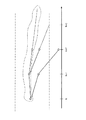
さらなるステップ(e)において、スイッチング状態シーケンスSSKaが選択され、関連するトルク軌道M及び(k+N)番目のサンプリング時間でのステータ磁束軌道φはそれぞれ所定値レンジ内にある。図3に示されるトルク軌道Mに基づいて、これは上部の2つのトルク軌道Mのみに適用されるが、下部のトルク軌道Mには適用されない。図3に示す所定値レンジは2つの点線で示された水平線で示される。ここで、それぞれの所定の値レンジは時間により変更され、回転電気機械のトルク及び回転電気機械1のステータ磁束に対する基準値から上流の閉ループ制御回路によって決定される。そのような閉ループ制御回路は当業者に既知である。他の実施形態として、次にスイッチング状態シーケンスSSKaが選択され、k番目のサンプリング時間から(k+N)番目のサンプリング時間に関する、関連するトルク軌道Mの軌道値MT,k、…、MT,k+Nと、関連するステータ磁束軌道φの軌道値φT,k、…、φT,k+Nは各所定の値レンジに近づく。
In a further step (e), the switching state sequence SSK a is selected and the associated torque trajectory M and the stator flux trajectory φ at the (k + N) th sampling time are each within a predetermined value range. Based on the torque trajectory M shown in FIG. 3, this applies only to the upper two torque trajectories M, but not to the lower torque trajectory M. The predetermined value range shown in FIG. 3 is indicated by a horizontal line indicated by two dotted lines. Here, each predetermined value range is changed by time, and is determined by a closed loop control circuit upstream from a reference value for the torque of the rotating electrical machine and the stator magnetic flux of the rotating
ステップ(f)において、選択されたスイッチング状態シーケンスSSKaに対して、回数nは、(k+N−1)番目のサンプリング時間と(k+N−1)番目のサンプリング時間に関する、関連するトルク軌道Mの軌道値MT,k+N-1、MT,k+N及びステータ磁束軌道φの軌道値φT,k+N-1及びφT,k+Nの外挿が各所定の値レンジの外になるまで、すなわち外挿値の1つがまず各所定の値レンジを越えるすなわち各所定の値レンジを横断するまで決定される。図3において、2つの上部の関連するトルク軌道Mに対する各外挿は点線で示されている。図3に示される1つの上部の関連するトルク軌道Mの外挿はk+3になるとすぐに所定の値レンジを越えるのに対して、より明確に示すために点線で規定されている、他の上部の関連するトルク軌道Mはk+3では依然として所定の値レンジ内にある。 In step (f), for the selected switching state sequence SSK a , the number n is the trajectory of the associated torque trajectory M with respect to the (k + N−1) th sampling time and the (k + N−1) th sampling time. Extrapolation of the values M T, k + N-1 , M T, k + N and the orbital values φ T, k + N-1 and φ T, k + N of the stator flux trajectory φ is outside the respective predetermined value ranges. Until one of the extrapolated values first exceeds each predetermined value range, i.e. crosses each predetermined value range. In FIG. 3, each extrapolation for the two upper associated torque trajectories M is indicated by dotted lines. The extrapolation of the associated torque trajectory M of one upper part shown in FIG. 3 exceeds the predetermined value range as soon as k + 3, whereas the other upper part, which is defined by a dotted line for more clearly showing The associated torque trajectory M is still within the predetermined value range at k + 3.
さらに、ステップ(g)において、選択されたスイッチング状態シーケンスSSKaのそれぞれに対して、関連する決定されたスイッチング遷移の組み合わせSKk、…、SKk+N-1が決定される。 Furthermore, in step (g), for each selected switching state sequence SSK a , the associated determined switching transition combinations SK k ,..., SK k + N−1 are determined.
さらに、ステップ(h)において、選択されたスイッチング状態シーケンスSSKaのそれぞれに対して、品質値cが回数nとスイッチング遷移sの全数から計算される。品質値cは好ましくはスイッチング遷移sの全数を回数nによって割り算することによって計算される。 Furthermore, in step (h), for each selected switching state sequence SSK a , a quality value c is calculated from the number n and the total number of switching transitions s. The quality value c is preferably calculated by dividing the total number of switching transitions s by the number n.
さらなるステップ(i)において、開始サンプリング時間kでの決定されたスイッチング状態組み合わせSKkは選択されたスイッチング状態組み合わせSKa,kとして設定され、このとき、関連する選択されたスイッチング状態シーケンスSSKaの品質値cが最小となる。 In a further step (i), the switching state combination SK k determined at the starting sampling time k is switching state combination SK a selected, is set as k, in this case, the associated selected switching state sequences SSK a The quality value c is minimized.
最後に、ステップ(j)において、ステップ(a)から(i)が反復され、k=k+1である。すなわちk=k+1に対してステップ(a)から(i)によって上記したシーケンスにしたがってスイッチング状態組み合わせSKa,kの選択が行なわれる。ここでNはステップ(a)から(j)のそれぞれに対して一定である。 Finally, in step (j), steps (a) to (i) are repeated, k = k + 1. That is, for k = k + 1, the switching state combination SK a, k is selected according to the sequence described above in steps (a) to (i). Here, N is constant for each of steps (a) to (j).
ステップ(b)から(j)によって、特に、外挿によって、全システムすなわち回転電気機械1および関連する変換器回路2のさらなるふるまいを予測することが可能である。先行する選択されたスイッチング状態組み合わせSKa,k-1に基づいて、先行する選択されたスイッチング状態組み合わせSKa,k-1から選択されたスイッチング状態組み合わせSKa,kへの遷移の数に関しておよび回転電気機械1のトルク及び回転電気機械1のステータ磁束に対する各所定の値レンジに関して最適なスイッチング状態組み合わせSKa,kを選択することは可能である。変換器回路2内のパワー半導体スイッチに対するスイッチング操作の数を低減してパワー半導体スイッチのスイッチング周波数を低減することは可能である。パワー半導体スイッチは有利なことにスイッチング周波数が低減されたことにより熱損失が少なくなるのでエネルギ消費が低くなる。これによって結果的にパワー半導体スイッチはよりゆっくりと劣化し、損失あるいは破壊に対する保護を大きくすることができる。
By means of steps (b) to (j), in particular by extrapolation, it is possible to predict further behavior of the entire system, i.e. the rotating
ステップ(a)から(j)はソフトウェアとして実装され、このソフトウェアは例えば特にデジタルシグナルプロセッサを用いてコンピュータシステム内に取り込み、当該コンピュータシステム上で動作させることができる。 Steps (a) to (j) are implemented as software, which can be taken into a computer system and operated on the computer system, for example using a digital signal processor.
上記したように、図1はm=3個の電圧レベルに対する変換器回路2を示し、DC電圧回路3がm−2個の副接続NPすなわち単一の副接続NPを有する。m(m≧3)個の電圧レベルを接続する変換器回路2の一般的な場合において、変換器回路2はDC電圧回路3でm−2個の副接続NPを有する。本発明による方法のステップ(d)に関連して、このことは、スイッチング状態シーケンスSSKのそれぞれに対してm−2個の副接続NPでの電位に対するm−2電位軌道UNPは、開始サンプリング時間kからサンプリング時間k+Nまでに対して回転電気機械1及び変換器回路2の決定された状態値セットXe,k、…、Xe,k+Nから計算される。さらに、m≧3のとき、ステップ(e)に関して、スイッチング状態シーケンスSSKaが選択され、加えて、(k+N)番目のサンプリング時間での関連するm−2の電位軌道UNPは各場合において所定の値レンジ内にあるか、あるいは、k番目のサンプリング値から(k+N)番目のサンプリング時間までに関する、関連するm−2個の電位軌道の軌道値UNP, k、…UNP, k+Nは、それぞれの所定の値レンジに近づく。さらに、m≧3のときに、ステップ(f)に関して、選択されたスイッチング状態シーケンスSSKaのそれぞれに対して、回数nは、(k+N−1)番目のサンプリング時間及び(k+N)番目のサンプリング時間に関して、関連するトルク軌道Mの軌道値MT,k+N-1及びMT,k+N、あるいはステータ磁束軌道φの軌道値φT,k+N-1及びφT,k+N、あるいはm−2個の電位軌道の軌道値の外挿が各所定の値レンジの外になるまで決定される。m≧3のとき、ステップ(a)から(c)及び(g)から(j)までが維持される。
As described above, FIG. 1 shows the
m≧3のとき、ステップ(b)から(j)によって、特に、外挿によって、全システムすなわち回転電気機械1及び関連する変換器回路2のさらなるふるまいを予測することが可能であり、したがって、先行する選択されたスイッチング状態組み合わせSKa,k-1に基づいてかつ先行する選択されたスイッチング状態組み合わせSKa,k-1から選択されたスイッチング状態組み合わせSKa,kへの遷移の数に関して、かつ、回転電気機械1のトルク、回転電気機械1のステータ磁束そしてm−2個の副接続NPでのm−2個の電位に対する、各所定の値レンジに関連して、最適なスイッチング状態組み合わせSKa,kを常に選択することが可能である。すなわち、上記したように、変換器回路2内のパワー半導体スイッチに対するスイッチング操作の数を低減し、これによって、パワー半導体スイッチのスイッチング周波数を低減することが可能である。
When m ≧ 3, it is possible to predict the further behavior of the entire system, ie the rotating
概して、ステップ(b)及び(c)は有利なことにステップ(k)において削除され、先行する選択されたスイッチング状態組み合わせSKa,k-1にたいするスイッチング状態シーケンスSSKが形成され、スイッチング状態シーケンスSSKはこの場合、一列内で互いに隣接された、N個先行する選択されたスイッチング状態組み合わせSKa,k-1の構成である。さらに、先行する選択されたスイッチング状態組み合わせSKa,k-1は選択されたスイッチング状態組み合わせSKa,kとして設定され、最後に、ステップ(d)が適用され、ステップ(e)から(i)は、関連するトルク軌道Mの軌道値MT,k、…、MT,k+N、及びk番目のサンプリング時間から(k+N)番目のサンプリング時間までに関する関連するステータ磁束軌道φの軌道値φT,k、…、φT,k+Nが各所定の値レンジ内にあるならば、省略できる。m≧3のとき、ステップ(k)において、ステップ(b)及び(c)が省略され、先行する選択されたスイッチング状態組み合わせSKa,k-1に対するスイッチング状態シーケンスSSKが形成され、スイッチング状態シーケンスSSKはこの場合、一列内に隣接された、N個の先行する選択されたスイッチング状態組み合わせSKa,k-1である。さらに、先行する選択されたスイッチング状態組み合わせSKa,kは選択されたスイッチング状態組み合わせSKa,kとして設定され、最後にステップ(d)が適用され、ステップ(e)から(i)は、k番目のサンプリング時間から(k+N)番目のサンプリング時間までに関連する、関連するトルク値MT,k、…、MT,k+Nと、関連するステータ磁束軌道φの軌道値φT,k、…、φT,k+Nと、関連するm−2個の電位軌道UNP軌道値UNP,k、…、UNP,k+Nが所定の値レンジ内にあるならば、省略される。 In general, steps (b) and (c) are advantageously deleted in step (k) to form a switching state sequence SSK for the preceding selected switching state combination SK a, k−1 and switching state sequence SSK. Is in this case the configuration of N preceding selected switching state combinations SK a, k−1 adjacent to each other in a row. Furthermore, the preceding selected switching state combination SK a, k-1 is set as the selected switching state combination SK a, k and finally step (d) is applied and steps (e) to (i) , M T, k ,..., M T, k + N of the associated torque trajectory M, and the orbital value φ of the associated stator magnetic flux trajectory φ with respect to the k th sampling time to the (k + N) th sampling time. If T, k ,..., Φ T, k + N are within each predetermined value range, they can be omitted. When m ≧ 3, in step (k), steps (b) and (c) are omitted, and a switching state sequence SSK for the preceding selected switching state combination SK a, k−1 is formed. The SSK is in this case the N preceding selected switching state combinations SK a, k−1 that are adjacent in a row. Furthermore, the preceding selected switching state combination SK a, k is set as the selected switching state combination SK a, k and finally step (d) is applied, and steps (e) to (i) are k th related to the sampling time to (k + N) -th sampling time, associated torque value M T, k, ..., M T, k + N and the associated trajectory values phi T, k of the stator flux trajectory phi, ..., o T, k + N and the associated m-2 potential orbital U NP orbital values U NP, k , ..., U NP, k + N are omitted if they are within a predetermined value range. .
このようにして、ステップ(b)及び(c)及びステップ(e)から(i)が省略できるので、計算時間が節約できる。軌道値MT,k、…、MT,k+N及びφT,k、…φT,k+N及びUNP,k、…、UNP,k+Nが満足されないならば、ステップ(b)から(i)が適用されるがステップ(k)は適用されない。 In this way, steps (b) and (c) and steps (e) to (i) can be omitted, so that calculation time can be saved. The trajectory values M T, k, ..., M T, k + N and φ T, k, ... φ T , k + N and U NP, k, ..., U NP, if k + N is not satisfied, the step ( b) to (i) are applied, but step (k) is not applied.
ステップ(k)は同様にしてソフトウェアとして実装され、このソフトウェアは例えば特にデジタルシグナルプロセッサを用いてコンピュータシステム内に取り込み、当該コンピュータシステム上で動作させることができる。 Step (k) is likewise implemented as software, which can be taken into a computer system and run on it, for example using a digital signal processor.
トルク軌道Mの軌道値MT,k+N-1、MT,k+Nの外挿として一次外挿(linear extrapolation)が好適し、ステータ磁束軌道φの軌道値φT,k+N-1、φT,k+Nの外挿として二次外挿(quadratic extrapolation)が好適することがわかった。この場合、ステータ磁束軌道φに対する二次外挿の選択と、トルク軌道Mに対する一次外挿の選択とを組み合わせることによって、全システムのふるまいを特に正確に予測することが可能になる。スイッチング状態組み合わせSKa,kの選択がより正確になり、その結果、パワー半導体スイッチのスイッチング周波数をさらに低減することが可能になる。一方、m≧3のとき、トルク軌道Mの軌道値MT,k+N-1、MT,k+N及びm−2個の電位軌道UNPの軌道値UNP,k+N-1及びUNP,k+Nの外挿としてそれぞれ一次外挿が選択可能であり、ステータ磁束軌道φの軌道値φT,k+N-1及びφT,k+Nの外挿としては二次外挿が選択可能であり、この場合、上記と同様の利点が得られる。 A linear extrapolation is suitable as an extrapolation of the trajectory values M T, k + N−1 and M T, k + N of the torque trajectory M, and the trajectory value φ T, k + N− of the stator magnetic flux trajectory φ. 1 It was found that quadratic extrapolation is suitable as an extrapolation of φ T, k + N. In this case, by combining the selection of secondary extrapolation with respect to the stator magnetic flux trajectory φ and the selection of primary extrapolation with respect to the torque trajectory M, it becomes possible to predict the behavior of the entire system particularly accurately. The selection of the switching state combination SK a, k becomes more accurate, and as a result, the switching frequency of the power semiconductor switch can be further reduced. On the other hand, when m ≧ 3, the trajectory values M T, k + N−1 and M T, k + N of the torque trajectory M and the trajectory values U NP, k + N−1 of the m−2 potential trajectories U NP And U NP, k + N can be selected as primary extrapolation, and stator flux trajectory φ trajectory values φ T, k + N-1 and φ T, k + N can be extrapolated as extrapolation. Extrapolation can be selected, in which case the same advantages as described above are obtained.
トルク軌道Mの軌道値MT,k+N-1、MT,k+N及びステータ磁束軌道φの軌道値φT,k+N-1、φT,k+Nの外挿として一次外挿を選択することも可能であり、この場合、m≧3である。トルク軌道Mの軌道値MT,k+N-1、MT,k+N及びステータ磁束軌道φの軌道値φT,k+N-1及びφT,k+Nの外挿としてそれぞれ一次外挿が選択されることに加えて、m−2個の電位軌道UNPの軌道値UNP,k+N-1、UNP,k+Nの外挿として一次外挿が選択される。
その他の可能性として、トルク軌道Mの軌道値MT,k+N-1、MT,k+N及びステータ磁束軌道φの軌道値φT,k+N-1及びφT,k+Nの外挿として二次外挿を選択することも可能であり、この場合、m≧3である。各場合において、トルク軌道Mの軌道値MT,k+N-1、MT,k+N及びステータ磁束軌道φの軌道値φT,k+N-1、φT,k+Nの外挿として二次外挿が選択されることに加えて、m−2個の電位軌道UNPの軌道値UNP,k+N-1、UNP,k+Nの外挿として一次外挿が選択される。
Extrapolation of the trajectory values M T, k + N-1 and M T, k + N of the torque trajectory M and the trajectory values φ T, k + N-1 and φ T, k + N of the stator magnetic flux trajectory φ It is also possible to select an insertion, in which case m ≧ 3. As an extrapolation of the trajectory values M T, k + N-1 and M T, k + N of the torque trajectory M and the trajectory values φ T, k + N-1 and φ T, k + N of the stator magnetic flux trajectory φ, respectively. In addition to selecting extrapolation, primary extrapolation is selected as extrapolation of orbital values U NP, k + N−1 , U NP, k + N of m−2 potential trajectories U NP .
As other possibilities, the trajectory values M T, k + N-1 and M T, k + N of the torque trajectory M and the trajectory values φ T, k + N-1 and φ T, k + N of the stator magnetic flux trajectory φ It is also possible to select a secondary extrapolation as an extrapolation of, where m ≧ 3. In each case, the trajectory values M T, k + N-1 and M T, k + N of the torque trajectory M and the trajectory values φ T, k + N-1 and φ T, k + N of the stator magnetic flux trajectory φ In addition to selecting the secondary extrapolation as the interpolation, the primary extrapolation is performed as the extrapolation of the orbital values U NP, k + N-1 and U NP, k + N of the m−2 potential trajectories U NP. Selected.
1 回転電気機械
2 3つの電圧レベルを接続するための変換機回路
3 DC電圧回路
4 一部変換器システム
5 第1のスイッチ群
6 第2のスイッチ群
7 第3のスイッチ群
DESCRIPTION OF
Claims (11)
(a)前記変換器回路の位相(u,v,w)を、前記変換器回路内のパワー半導体スイッチに対するスイッチング状態から選択されたスイッチング状態組み合わせ(SKa,k)にしたがってDC電圧回路に接続すること、を有し、前記スイッチング状態組み合わせ(SKa,k)の選択は以下のさらなるステップ
(b)サンプリング回数から選択可能な数Nに対する開始サンプリング時間がkのときに、N個のサンプリング時間(N≧1)のそれぞれにおいて取りうるすべてのスイッチング状態組み合わせ(SKk,…,SKk+N-1)を決定し、
(c)開始サンプリング時間kで各決定されたスイッチング状態組み合わせ(SKk)に対するスイッチング状態シーケンス(SSK)を形成し、各スイッチング状態シーケンス(SSK)は、一列内の互いに隣り合うN個のサンプリング時間の決定されたスイッチング状態組み合わせ(SKk,…,SKk+N-1)を構成し、前記スイッチング状態組み合わせ(SKk,…,SKk+N-1)は開始サンプリング時間kでの各スイッチング状態組み合わせ(SKk)に関連し、
(d)スイッチング状態シーケンス(SSK)のそれぞれに対して、開始サンプリング時間kからサンプリング時間k+Nまでについて、前記回転電気機械及び前記変換器回路の決定された状態値セット(Xe,k、…、Xe,k+N)から、前記回転電気機械のトルク軌道(M)と、前記回転電気機械のステータ磁束軌道(φ)を計算し、
(e)スイッチング状態シーケンス(SSKa)を選択し、この場合、(k+N)番目のサンプリング時間での関連するトルク軌道(M)と、ステータ磁束軌道(φ)はそれぞれ所定の値レンジ内にあるかあるいは、k番目のサンプリング時間から(k+N)番目のサンプリング時間までに関して、関連するトルク軌道(M)の軌道値(MT,k、…、MT,k+N)と、関連するステータ磁束軌道(φ)の軌道値(φT,k、…、φT,k+N)とは各所定の値レンジに近づき、
(f)選択されたスイッチング状態シーケンス(SSKa)のそれぞれに対して、(k+N−1)番目のサンプリング時間及び(k+N)番目のサンプリング時間に関して、関連するトルク軌道(M)の軌道値(MT,k+N-1、…、MT,k+N)の外挿あるいはステータ磁束軌道(φ)の軌道値(φT,k+N-1、…、φT,k+N)が各所定の値レンジ外になるまで、回数nを決定し、
(g)選択されたスイッチング状態シーケンス(SSKa)のそれぞれに対して、関連する決定されたスイッチング状態組み合わせ(SKk,…,SKk+N-1)のスイッチング遷移sの全体数を決定し、
(h)選択されたスイッチング状態シーケンス(SSKa)のそれぞれに対して、回数n及びスイッチング遷移sの全体数から品質値cを計算し、
(i)開始サンプリング時間kでの決定されたスイッチング状態組み合わせ(SKk)を、関連する選択されたスイッチング状態シーケンス(SSKa)の品質値cが最も小さくなる選択されたスイッチング状態組み合わせ(SKa,k)として設定し、
(j)ステップ(a)から(i)を反復する(k=k+1)ことを具備することを特徴とする方法。 Method of operating a rotating electrical machine, connected to a converter circuit having a DC voltage circuit in phase to connect m (m ≧ 2) voltage levels, the following step (a) said converter Connecting the phase (u, v, w) of the circuit to a DC voltage circuit according to a switching state combination (SK a, k ) selected from the switching states for power semiconductor switches in the converter circuit. The switching state combination (SK a, k ) is selected by the following further step (b): when N sampling times (N ≧ 1) when the starting sampling time is k for a selectable number N from the number of sampling times Determine all possible switching state combinations (SK k ,..., SK k + N−1 ) in each;
(C) forming a switching state sequence (SSK) for each determined switching state combination (SK k ) at a starting sampling time k, wherein each switching state sequence (SSK) is N sampling times adjacent to each other in a row; Of the determined switching states (SK k ,..., SK k + N−1 ), and the switching state combinations (SK k ,..., SK k + N−1 ) are switched at the start sampling time k. Related to the state combination (SK k ),
(D) For each switching state sequence (SSK), the determined state value sets (X e, k ,...) Of the rotating electrical machine and the converter circuit for the starting sampling time k to the sampling time k + N. X e, k + N ) to calculate the torque trajectory (M) of the rotating electrical machine and the stator magnetic flux trajectory (φ) of the rotating electrical machine,
(E) Select the switching state sequence (SSK a ), where the associated torque trajectory (M) and stator flux trajectory (φ) at the (k + N) th sampling time are each within a predetermined value range Or, from the kth sampling time to the (k + N) th sampling time, the associated torque trajectory (M) trajectory values (M T, k ,..., M T, k + N ) and the associated stator flux The orbital value (φ T, k , ..., φ T, k + N ) of the orbit (φ) approaches each predetermined value range,
(F) For each selected switching state sequence (SSK a ), for the (k + N−1) th sampling time and the (k + N) th sampling time, the trajectory value (M) of the associated torque trajectory (M). T, k + N-1 , ..., M T, k + N ) or the stator flux orbit (φ) orbital value (φ T, k + N-1 , ..., φ T, k + N ) The number of times n is determined until it falls outside each predetermined value range,
(G) For each selected switching state sequence (SSK a ), determine the total number of switching transitions s of the associated determined switching state combination (SK k ,..., SK k + N−1 ). ,
(H) for each selected switching state sequence (SSK a ), calculate a quality value c from the number n and the total number of switching transitions s;
(I) the determined switching state combination at the starting sampling time k to (SK k), associated selected quality value c is smallest selected switching state combination (SK a switching state sequence (SSK a) , k )
(J) repeating steps (a) to (i) (k = k + 1).
ステップ(d)に関連して、スイッチング状態シーケンス(SSK)のそれぞれに対してm−2個の副接続(NP)での電位に対するm−2個の電位軌道(UNP)は、開始サンプリング時間kからサンプリング時間k+Nまでについて前記回転電気機械及び前記変換器回路の決定された状態値セット(Xe,k、…、Xe,k+N)から計算され、
ステップ(e)に関して、スイッチング状態シーケンス(SSKa)が選択され、(k+N)番目のサンプリング時間での関連するm−2個の電位軌道(UNP)はそれぞれ、所定の値レンジ内にあるか、あるいは、k番目のサンプリング値から(k+N)番目のサンプリング時間までに関して、関連するm−2個の電位軌道(UNP)の軌道値(UNP, k、…UNP, k+N)は、それぞれの所定の値レンジに近づき、
ステップ(f)に関して、選択されたスイッチング状態シーケンス(SSKa)のそれぞれに対して、回数nは、(k+N−1)番目のサンプリング時間及び(k+N)番目のサンプリング時間に関して、関連するトルク軌道(M)の軌道値(MT,k+N-1)及び(MT,k+N)あるいはステータ磁束軌道φの軌道値(φT,k+N-1)及び(φT,k+N、)あるいはm−2個の電位軌道(UNP)の軌道値(UNP,k、…、UNP,k+N)の外挿が各所定の値レンジの外になるまで決定されることを特徴とする請求項1記載の方法。 When m ≧ 3, the converter circuit for connecting m voltage levels is a DC voltage circuit and has m−2 sub-connections (NP);
In connection with step (d), m−2 potential trajectories (U NP ) for potentials at m−2 sub-connections (NP) for each of the switching state sequences (SSK) calculated from a determined set of state values (X e, k ,..., X e, k + N ) of the rotating electrical machine and the converter circuit for k to sampling time k + N;
For step (e), a switching state sequence (SSK a ) is selected and whether the associated m−2 potential trajectories (U NP ) at the (k + N) th sampling time are each within a predetermined value range. Or, from the kth sampling value to the (k + N) th sampling time, the orbital values (U NP, k ,... U NP, k + N ) of the associated m−2 potential trajectories (U NP ) are , Approaching each predetermined value range,
For step (f), for each selected switching state sequence (SSK a ), the number n is the associated torque trajectory (with respect to the (k + N−1) th sampling time and the (k + N) th sampling time ( M) orbital values (M T, k + N-1 ) and (M T, k + N ) or stator flux orbits φ (φ T, k + N-1 ) and (φ T, k + N )) Or m-2 potential orbits (U NP ) orbital values (U NP, k ,..., U NP, k + N ) are determined until the extrapolation is outside each predetermined value range. The method of claim 1 wherein:
Applications Claiming Priority (2)
| Application Number | Priority Date | Filing Date | Title |
|---|---|---|---|
| EP04405767A EP1670135B1 (en) | 2004-12-10 | 2004-12-10 | Method of operating a rotary electrical machine |
| EP04405767.7 | 2004-12-10 |
Publications (2)
| Publication Number | Publication Date |
|---|---|
| JP2006174697A true JP2006174697A (en) | 2006-06-29 |
| JP4732883B2 JP4732883B2 (en) | 2011-07-27 |
Family
ID=34932401
Family Applications (1)
| Application Number | Title | Priority Date | Filing Date |
|---|---|---|---|
| JP2005357817A Expired - Fee Related JP4732883B2 (en) | 2004-12-10 | 2005-12-12 | Method for operating a rotating electrical machine |
Country Status (5)
| Country | Link |
|---|---|
| US (1) | US7256561B2 (en) |
| EP (1) | EP1670135B1 (en) |
| JP (1) | JP4732883B2 (en) |
| AT (1) | ATE428215T1 (en) |
| DE (1) | DE502004009328D1 (en) |
Cited By (11)
| Publication number | Priority date | Publication date | Assignee | Title |
|---|---|---|---|---|
| JP2009072058A (en) * | 2007-09-10 | 2009-04-02 | Abb Res Ltd | Method for operating rotary electric machine |
| JP2011519253A (en) * | 2007-12-20 | 2011-06-30 | アーベーベー・リサーチ・リミテッド | Electric rotating machine operation method |
| JP2011152038A (en) * | 2010-01-22 | 2011-08-04 | Abb Research Ltd | Control device for rotating electric machine |
| DE102011002510A1 (en) | 2010-01-11 | 2011-09-01 | Denso Corporation | Control device for a multi-phase rotary machine |
| DE102011001259A1 (en) | 2010-03-18 | 2012-01-19 | Denso Corporation | Regulating device for a rotating electrical machine |
| US8164311B2 (en) | 2009-04-10 | 2012-04-24 | Denso Corporation | Control device for electric rotating machine |
| US8310186B2 (en) | 2009-08-25 | 2012-11-13 | Denso Corporation | Apparatus for carrying out improved control of rotary machine |
| US8427088B2 (en) | 2009-07-08 | 2013-04-23 | Denso Corporation | Apparatus for carrying out improved control of rotary machine |
| US8686673B2 (en) | 2010-02-08 | 2014-04-01 | Denso Corporation | Control device for electric rotary machine |
| WO2019111372A1 (en) * | 2017-12-07 | 2019-06-13 | 三菱電機株式会社 | Power conversion device |
| US11489478B2 (en) | 2019-01-16 | 2022-11-01 | Mitsubishi Electric Corporation | Power conversion device |
Families Citing this family (7)
| Publication number | Priority date | Publication date | Assignee | Title |
|---|---|---|---|---|
| JP2008295161A (en) * | 2007-05-23 | 2008-12-04 | Daikin Ind Ltd | Power conversion device |
| PL2163955T3 (en) | 2008-09-11 | 2011-08-31 | Abb Research Ltd | State estimation method based on a Kalman filter for capacitive and inductive motor states |
| DE102011002657A1 (en) | 2011-01-13 | 2012-07-19 | Converteam Gmbh | Method for operating an inverter of an arrangement for generating electrical energy |
| JP5387614B2 (en) | 2011-05-16 | 2014-01-15 | 株式会社デンソー | Rotating machine control device |
| EP2546979A1 (en) | 2011-07-15 | 2013-01-16 | ABB Research Ltd. | Method for controlling harmonics and resonances in an inverter |
| EP2725706A1 (en) * | 2012-10-23 | 2014-04-30 | ABB Technology AG | Model predictive control with reference tracking |
| EP2733842B1 (en) * | 2012-11-15 | 2018-07-04 | ABB Schweiz AG | Controlling an electrical converter |
Citations (4)
| Publication number | Priority date | Publication date | Assignee | Title |
|---|---|---|---|---|
| JPH0556655A (en) * | 1991-08-26 | 1993-03-05 | Meidensha Corp | Pwm arithmetic method of voltage type inverter |
| JPH07170751A (en) * | 1993-12-13 | 1995-07-04 | Toyo Electric Mfg Co Ltd | Three-level inverter device |
| JPH10174453A (en) * | 1996-12-13 | 1998-06-26 | Toshiba Corp | Inverter control device |
| JP2004222421A (en) * | 2003-01-15 | 2004-08-05 | Fuji Electric Fa Components & Systems Co Ltd | Power conversion apparatus |
Family Cites Families (5)
| Publication number | Priority date | Publication date | Assignee | Title |
|---|---|---|---|---|
| JPH0669305B2 (en) * | 1986-03-05 | 1994-08-31 | サンケン電気株式会社 | Inverter motor controller |
| FR2749717B1 (en) * | 1996-06-06 | 1998-07-31 | Alsthom Cge Alcatel | CONTROL METHOD OF A ROTATING MACHINE, SERVO SYSTEM FOR IMPLEMENTING SAID METHOD, ROTATING MACHINE PROVIDED WITH SUCH A SYSTEM |
| FR2777399B1 (en) * | 1998-04-09 | 2000-06-09 | Centre Nat Rech Scient | METHOD AND DEVICE FOR CONTROLLING A STATIC CONVERTER SUPPLYING A CURRENT SOURCE |
| FR2791488B1 (en) * | 1999-03-25 | 2002-09-20 | Schneider Electric Sa | MONITORING SYSTEM OF A VOLTAGE INVERTER |
| US7128687B2 (en) * | 2004-03-19 | 2006-10-31 | Ford Global Technologies, Llc | Electromechanically actuated valve control for an internal combustion engine |
-
2004
- 2004-12-10 EP EP04405767A patent/EP1670135B1/en active Active
- 2004-12-10 DE DE502004009328T patent/DE502004009328D1/en active Active
- 2004-12-10 AT AT04405767T patent/ATE428215T1/en active
-
2005
- 2005-12-07 US US11/295,546 patent/US7256561B2/en active Active
- 2005-12-12 JP JP2005357817A patent/JP4732883B2/en not_active Expired - Fee Related
Patent Citations (4)
| Publication number | Priority date | Publication date | Assignee | Title |
|---|---|---|---|---|
| JPH0556655A (en) * | 1991-08-26 | 1993-03-05 | Meidensha Corp | Pwm arithmetic method of voltage type inverter |
| JPH07170751A (en) * | 1993-12-13 | 1995-07-04 | Toyo Electric Mfg Co Ltd | Three-level inverter device |
| JPH10174453A (en) * | 1996-12-13 | 1998-06-26 | Toshiba Corp | Inverter control device |
| JP2004222421A (en) * | 2003-01-15 | 2004-08-05 | Fuji Electric Fa Components & Systems Co Ltd | Power conversion apparatus |
Cited By (18)
| Publication number | Priority date | Publication date | Assignee | Title |
|---|---|---|---|---|
| KR101442843B1 (en) | 2007-09-10 | 2014-09-23 | 에이비비 리써치 리미티드 | Method for operating a rotating electrical machine |
| JP2009072058A (en) * | 2007-09-10 | 2009-04-02 | Abb Res Ltd | Method for operating rotary electric machine |
| JP2011519253A (en) * | 2007-12-20 | 2011-06-30 | アーベーベー・リサーチ・リミテッド | Electric rotating machine operation method |
| KR101520518B1 (en) | 2007-12-20 | 2015-05-14 | 에이비비 리써치 리미티드 | Method for operating a rotating electric machine |
| US8164311B2 (en) | 2009-04-10 | 2012-04-24 | Denso Corporation | Control device for electric rotating machine |
| US8427088B2 (en) | 2009-07-08 | 2013-04-23 | Denso Corporation | Apparatus for carrying out improved control of rotary machine |
| US8310186B2 (en) | 2009-08-25 | 2012-11-13 | Denso Corporation | Apparatus for carrying out improved control of rotary machine |
| DE102011002510A1 (en) | 2010-01-11 | 2011-09-01 | Denso Corporation | Control device for a multi-phase rotary machine |
| US8421386B2 (en) | 2010-01-11 | 2013-04-16 | Denso Corporation | Control apparatus for multi-phase rotary machine |
| RU2547807C2 (en) * | 2010-01-22 | 2015-04-10 | Абб Рисерч Лтд | Rotating electric machine control method |
| JP2011152038A (en) * | 2010-01-22 | 2011-08-04 | Abb Research Ltd | Control device for rotating electric machine |
| US8686673B2 (en) | 2010-02-08 | 2014-04-01 | Denso Corporation | Control device for electric rotary machine |
| US8466642B2 (en) | 2010-03-18 | 2013-06-18 | Denso Corporation | Control apparatus for electric rotating machine |
| DE102011001259A1 (en) | 2010-03-18 | 2012-01-19 | Denso Corporation | Regulating device for a rotating electrical machine |
| WO2019111372A1 (en) * | 2017-12-07 | 2019-06-13 | 三菱電機株式会社 | Power conversion device |
| JPWO2019111372A1 (en) * | 2017-12-07 | 2020-10-01 | 三菱電機株式会社 | Power converter |
| US11177757B2 (en) | 2017-12-07 | 2021-11-16 | Mitsubishi Electric Corporation | Power conversion device |
| US11489478B2 (en) | 2019-01-16 | 2022-11-01 | Mitsubishi Electric Corporation | Power conversion device |
Also Published As
| Publication number | Publication date |
|---|---|
| DE502004009328D1 (en) | 2009-05-20 |
| JP4732883B2 (en) | 2011-07-27 |
| EP1670135B1 (en) | 2009-04-08 |
| US7256561B2 (en) | 2007-08-14 |
| ATE428215T1 (en) | 2009-04-15 |
| US20060125435A1 (en) | 2006-06-15 |
| EP1670135A1 (en) | 2006-06-14 |
Similar Documents
| Publication | Publication Date | Title |
|---|---|---|
| JP4732883B2 (en) | Method for operating a rotating electrical machine | |
| US20170310263A1 (en) | Apparatus and methods of controlling electric drive with reconfigurable winding | |
| JP2006109579A (en) | Motor drive unit and drive method | |
| US4336484A (en) | Motor control | |
| Moreira et al. | Simulation of a four phase switched reluctance motor including the effects of mutual coupling | |
| Roux et al. | On the use of a simplified model for switched reluctance motors | |
| RU2721225C2 (en) | Multilevel high-speed adjustable drive | |
| US8222845B2 (en) | Method for operating a rotating electric machine | |
| JP5329158B2 (en) | Operation method of rotating electrical machine | |
| US6512342B2 (en) | Brushless motor driving device | |
| Zheng et al. | Current optimization for a multi-phase machine under an open circuit phase fault condition | |
| JPH11122978A (en) | Drive current control method for dc brushless motor with independent winding | |
| Mehta et al. | Decoupled modeling of mutually coupled SRM based on net flux method | |
| Wendel et al. | Flux linkage-based model predictive current control for nonlinear PMSM drives | |
| Stillwagon et al. | Continuous conduction operation for mutually coupled switched reluctance machines | |
| WO1997025770A1 (en) | Ac motor with reactor connected to power source | |
| Guiti et al. | Direct Torque Control with ANN hysteresis controller for PMSM | |
| JP6545388B2 (en) | Motor drive device, motor system and refrigeration cycle device | |
| JPS6188785A (en) | Brushless dc motor | |
| KR100258408B1 (en) | Apparatus for driving motor by space vector control | |
| RU2150781C1 (en) | Method for controlling speed of three-phase motor | |
| Al-Badi et al. | MATLAB and PSPICE Dynamic Model of Axial-Field Permanent-Magnet Motor | |
| Peresada et al. | Passivity–based design of the flux observers for induction motors | |
| Gonzalez et al. | Fpga modulator for matrix converter | |
| SU970579A1 (en) | Thyratron electric motor |
Legal Events
| Date | Code | Title | Description |
|---|---|---|---|
| A621 | Written request for application examination |
Free format text: JAPANESE INTERMEDIATE CODE: A621 Effective date: 20080918 |
|
| A01 | Written decision to grant a patent or to grant a registration (utility model) |
Free format text: JAPANESE INTERMEDIATE CODE: A01 Effective date: 20110322 |
|
| A61 | First payment of annual fees (during grant procedure) |
Free format text: JAPANESE INTERMEDIATE CODE: A61 Effective date: 20110421 |
|
| FPAY | Renewal fee payment (event date is renewal date of database) |
Free format text: PAYMENT UNTIL: 20140428 Year of fee payment: 3 |
|
| R150 | Certificate of patent or registration of utility model |
Free format text: JAPANESE INTERMEDIATE CODE: R150 |
|
| R250 | Receipt of annual fees |
Free format text: JAPANESE INTERMEDIATE CODE: R250 |
|
| R250 | Receipt of annual fees |
Free format text: JAPANESE INTERMEDIATE CODE: R250 |
|
| LAPS | Cancellation because of no payment of annual fees |