US841663A - Recuperative furnace. - Google Patents
Recuperative furnace. Download PDFInfo
- Publication number
- US841663A US841663A US28225305A US1905282253A US841663A US 841663 A US841663 A US 841663A US 28225305 A US28225305 A US 28225305A US 1905282253 A US1905282253 A US 1905282253A US 841663 A US841663 A US 841663A
- Authority
- US
- United States
- Prior art keywords
- combustion
- chamber
- furnace
- retorts
- flues
- Prior art date
- Legal status (The legal status is an assumption and is not a legal conclusion. Google has not performed a legal analysis and makes no representation as to the accuracy of the status listed.)
- Expired - Lifetime
Links
Images
Classifications
-
- F—MECHANICAL ENGINEERING; LIGHTING; HEATING; WEAPONS; BLASTING
- F23—COMBUSTION APPARATUS; COMBUSTION PROCESSES
- F23G—CREMATION FURNACES; CONSUMING WASTE PRODUCTS BY COMBUSTION
- F23G5/00—Incineration of waste; Incinerator constructions; Details, accessories or control therefor
- F23G5/02—Incineration of waste; Incinerator constructions; Details, accessories or control therefor with pretreatment
- F23G5/027—Incineration of waste; Incinerator constructions; Details, accessories or control therefor with pretreatment pyrolising or gasifying stage
Definitions
- This invention relates more particularly to apparatus for heating retorts, muflies, &c., in which air is supplied to the generators or iireboxes to produce fuel-gas for heating the retorts, &c., and a secondary supply of air is delivered to and mingled with the combustible gases which constitute a part of the products of combustion in said generators or hrechambers.
- the invention consists in certain novel features of construction and in the peculiar arrangement and combinations of parts as hereinafter particularly described, and deiined in the claims.
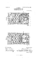
- Figure 1 is a vertical cross-section on the line 1 1, Figs. 3 and 4, through the front or iiring end of a furnace embodying the invention.
- Fig. 2 is a vertical cross-section on the line 2 3, Fig. 3, through the recuperator end of the furnace, the left-hand side being on the line 2 2 and the right-hand side on the line 3 3, Fig. 4.
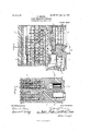
- Fig. 3 is a horizontal section at two different levels on the line ⁇ 4 5, Figs. 1 and 2, theleft-hand side being on the line4 4 and the right-hand side on the line 5 5, Fig. 4; and
- Fig. 4 is a vertical longitudinal section on the line 6 6, Figs. 1, 2, and 3.
- one generator or fire chamber is generally employed and if two are used they are arranged on opposite sides of the bench or at opposite ends of the furnace.
- the usual practice is to charge the generators or fire-boxes of these furnaces every time the retorts are drawn, the retorts being located directly above the feed-doors of the generators.
- the generators are ordinarily charged either ive or six times during a period of twenty-four hours. As the fuel in the generator burns down the gas resulting from its combustion will diiTer in composition, quantity, .and pressure from that pro- 5 cuted immediately after the generator is filled or charged.
- the generators of fire-boxes are arranged according to the present invention side by side, one on each side of the furnace, and are connected with each other in or adj acent to the gas zone or space. If now the generators are alternately filled or chargedfor example, one at two oclock and the other at four oclock-one generator will at all times be operating at a high capacity and the other at a low capacity, and the mingled gaseous products of both will be at all times of uniform composition, quantity, and pressure and an even heat will be obtained in theretort-chamber.
- recuperators-in the present instance four in numberkare located at the rear ends of the generators, and by this arrangement the supply of air to different parts of the furnace can be separately regulated so as to secure the most advantageous and economical results.
- c a designate the generators or fire-boxes, which are arranged side by side on opposite sides of the furnace and are connected with each other in or adjacent to the gas zone by openings b through the partition-wall between them.
- the generators are provided with grates c c.
- Flues d d extend horizontally from the rear ends of the generators a and are connected in like manner with each other by openings. b through the intervening Wall.
- the combustion or retort chamber e located above the generators and extensionflues d, communicates therewith through tapering nozzles or passages
- the retorts g g are supported at the ends by the walls of the furnace and at intermediate points by bridge walls or piers in the chamber e.
- h and 'i designate the gas-fines of the recuperators, the flues zfbeing arranged to take gas from the rear part of the bench or combus- IIO a, il, w, and as shown in Figs. l and 3.
- m, n, 0, and p designate the secondary airfiues of the recuperators.
- These air flues supply the necessary air to different parts of the bench or chamber c for complete combustion of the gas therein, the course of the air in its passage through said flues being indicated by arrows on the several figures of the drawing.
- the iiue m supplies the rear quarter of the bench, the iue n the next or second quarters, the flue o the third quarter, and the fiue p the fourth or front quarter.
- the upper iiues o and p communicate with the combustion chamber e through distributingducts g and r, while the upper fiue m communicates with said chamber through the duct s, and the upper flue n communicates with that part of the upper fiue m which is next to the center of the bench or furnace, as shown in Fig. 3.
- the upper flue m may be divided at the center by a partition t, as shown in Fig. 3, but this division is not essential, since by regulating the admission of air into the iiues m and n the quantity delivered to the different parts of the combustionchamber e supplied by said flues can be varied as desired.
- the primary air-supply is conducted to the generators below the grates c through fiues All the air-supply flues are provided with dampers or valves (not shown) for regulating the primary supply under the grate and the secondary supply to different parts of the combustion-chamber.
- dampers or valves not shown
- the furnace shown in the drawings there are four recuperators, two on each side of the furnace, and eight valves or dampers for the control and regulation of the primary air-supply and eight for the secondary air-supply; but any kind of recuperators-such, for example, as that shown and describedl in United States Letters Patent No. 659,602, issued to me October 9, 1900- with any suitable number and arrangement of flues for supplying air to the furnace, may be used.
- the generators, combustion or retort chamber, with the retorts and the recuperators, are all mounted in and inclosed by a vbrick setting or other suitable walls, substantially as shown in the drawings.
- the furnace constructed as herein shown and described operates as follows:
- the generators a are filled or charged at intervals with coke either direct from the retorts g by means of a charging-funnel or with cold coke or Iother fuel. Air is admitted under the grates c through the flues u, i), w, and fr, as indicated by arrows in Figs. l, 3, and 4, and passing through the hot coke or other fuel in the generators first produces carbon dioxid, which in contact with the incandescent fuel is partly converted into carbon monoxid.
- I claim- 1 In a recuperative furnace two generator or re chambers arranged side by side, and communicating with each other through openings in the wall between them, a combustion-chamber located above and communicating'with both generator or fire chambers through passages in the upper walls thereof, and retorts mounted in said combustionchamber, substantially as described.
- a combustion-chamber communicating with said generator-chambers, retorts mounted in said combustion-chamber7 and reeuperators having primary air-ducts leading into the communicating with each other through openings in the Wall between them, a comlbustion-ehamber located above and communicating with said generator-chambers, retorts mounted in said combustion-chamber, and recuperators having primary airilues leading into the generator-chambers, secondary air-fines leading into the combustion-chamber, and gas escape-dues leading from the combustion-chamber and adjoining the air-flues, said Chambers and recuperators being inclosed together, substantially as described.
Landscapes
- Engineering & Computer Science (AREA)
- Mechanical Engineering (AREA)
- General Engineering & Computer Science (AREA)
- Waste-Gas Treatment And Other Accessory Devices For Furnaces (AREA)
Description
No. 841,663. PATENTBD 11111.22, 1907.
RBRBDEL.
RECUPERATIVB PURNAGE. APPLICATION FILED 001.11. 1905.
2 SHEETS-s111121' 1.
rus Nomzls PETERS cn.. wAsmNaroN, D. c.
UNITED sTATEs PATENT oEErcE.
Specification of Letters Patent.
Patented Jan. 22, 1907'.
Application filed October 11, 1905. Serial No. 282.253.
To @ZZ whom 1f/.may concern: A
Be it known that I, FREDERICK BEEDEL, a
` citizen of the United States, residing at Milwaukee, in the county of Milwaukee and State of Wisconsin, have invented certain new and useful Improvements in Recuperative Furnaces, of which the following is a specification, reference being had to the accompanying drawings, forming a part thereof.
This invention relates more particularly to apparatus for heating retorts, muflies, &c., in which air is supplied to the generators or iireboxes to produce fuel-gas for heating the retorts, &c., and a secondary supply of air is delivered to and mingled with the combustible gases which constitute a part of the products of combustion in said generators or hrechambers.
The invention consists in certain novel features of construction and in the peculiar arrangement and combinations of parts as hereinafter particularly described, and deiined in the claims.
In the accompanying drawings like characters designate the same parts in the several` figures.
Figure 1 is a vertical cross-section on the line 1 1, Figs. 3 and 4, through the front or iiring end of a furnace embodying the invention. Fig. 2 is a vertical cross-section on the line 2 3, Fig. 3, through the recuperator end of the furnace, the left-hand side being on the line 2 2 and the right-hand side on the line 3 3, Fig. 4. Fig. 3 is a horizontal section at two different levels on the line`4 5, Figs. 1 and 2, theleft-hand side being on the line4 4 and the right-hand side on the line 5 5, Fig. 4; and Fig. 4 is a vertical longitudinal section on the line 6 6, Figs. 1, 2, and 3.
According to the ordinary method of building recuperative furnaces one generator or fire chamber is generally employed and if two are used they are arranged on opposite sides of the bench or at opposite ends of the furnace. The usual practice is to charge the generators or fire-boxes of these furnaces every time the retorts are drawn, the retorts being located directly above the feed-doors of the generators. The generators are ordinarily charged either ive or six times during a period of twenty-four hours. As the fuel in the generator burns down the gas resulting from its combustion will diiTer in composition, quantity, .and pressure from that pro- 5 duced immediately after the generator is filled or charged. To compensate for this variation in the composition, quantity, and pressure, the generators of fire-boxes are arranged according to the present invention side by side, one on each side of the furnace, and are connected with each other in or adj acent to the gas zone or space. If now the generators are alternately filled or chargedfor example, one at two oclock and the other at four oclock-one generator will at all times be operating at a high capacity and the other at a low capacity, and the mingled gaseous products of both will be at all times of uniform composition, quantity, and pressure and an even heat will be obtained in theretort-chamber.
For controlling and regulating the combustion by the secondary air-supply the recuperators-in the present instance four in numberkare located at the rear ends of the generators, and by this arrangement the supply of air to different parts of the furnace can be separately regulated so as to secure the most advantageous and economical results.
Referring noW to the drawings for specific explanation of one among various forms in which the invention may be embodied, c a designate the generators or fire-boxes, which are arranged side by side on opposite sides of the furnace and are connected with each other in or adjacent to the gas zone by openings b through the partition-wall between them. The generators are provided with grates c c. Flues d d extend horizontally from the rear ends of the generators a and are connected in like manner with each other by openings. b through the intervening Wall.
The combustion or retort chamber e, located above the generators and extensionflues d, communicates therewith through tapering nozzles or passages The retorts g g are supported at the ends by the walls of the furnace and at intermediate points by bridge walls or piers in the chamber e. In the present case there are twelve so-called Hthrough-retorts-7 arranged in three vertical tiers, each tier consisting of four retorts but the number and arrangement of the retorts may be varied, and in place of through-retorts what are known as back- IOO to-back retorts may be used, without materially affecting the operation of the apparatus so far as the improvements constituting the present invention are concerned.
h and 'i designate the gas-fines of the recuperators, the flues zfbeing arranged to take gas from the rear part of the bench or combus- IIO a, il, w, and as shown in Figs. l and 3.
tion-chamber e, while the ues i take gas from the front or generator part of the bench or combustion-chamber by way of the ducts j, lc, and l.
m, n, 0, and p designate the secondary airfiues of the recuperators. These air flues supply the necessary air to different parts of the bench or chamber c for complete combustion of the gas therein, the course of the air in its passage through said flues being indicated by arrows on the several figures of the drawing. The iiue m supplies the rear quarter of the bench, the iue n the next or second quarters, the flue o the third quarter, and the fiue p the fourth or front quarter. The upper iiues o and p communicate with the combustion chamber e through distributingducts g and r, while the upper fiue m communicates with said chamber through the duct s, and the upper flue n communicates with that part of the upper fiue m which is next to the center of the bench or furnace, as shown in Fig. 3. The upper flue m may be divided at the center by a partition t, as shown in Fig. 3, but this division is not essential, since by regulating the admission of air into the iiues m and n the quantity delivered to the different parts of the combustionchamber e supplied by said flues can be varied as desired.
The primary air-supply is conducted to the generators below the grates c through fiues All the air-supply flues are provided with dampers or valves (not shown) for regulating the primary supply under the grate and the secondary supply to different parts of the combustion-chamber. In the furnace shown in the drawings there are four recuperators, two on each side of the furnace, and eight valves or dampers for the control and regulation of the primary air-supply and eight for the secondary air-supply; but any kind of recuperators-such, for example, as that shown and describedl in United States Letters Patent No. 659,602, issued to me October 9, 1900- with any suitable number and arrangement of flues for supplying air to the furnace, may be used.
The generators, combustion or retort chamber, with the retorts and the recuperators, are all mounted in and inclosed by a vbrick setting or other suitable walls, substantially as shown in the drawings.
The furnace constructed as herein shown and described operates as follows: The generators a, are filled or charged at intervals with coke either direct from the retorts g by means of a charging-funnel or with cold coke or Iother fuel. Air is admitted under the grates c through the flues u, i), w, and fr, as indicated by arrows in Figs. l, 3, and 4, and passing through the hot coke or other fuel in the generators first produces carbon dioxid, which in contact with the incandescent fuel is partly converted into carbon monoxid. This carbon monoxid `passing freely through the openings b from either generator which for the time being is operating at a higher capacity mixes with the gas .in the other generator, thereby equalizing the pressure in both generators, so that an even supply of gas of uniform pressure and composition is supplied to the combustion or retort chamber l. through the nozzles or passages Meeting with the air from the several iiues leading into the combustion-chamber the gases are completely burned and passing upwardly and downwardly between and around the retorts g impart their heat thereto. rlhe waste or spent gases pass downwardly from the combustion-chamber directly into the flues 7L and through the ducts j, c, and Z into the flues i, from which they escape in the lower part of the furnace into a collecting flue or chimney, as indicated by arrows on the several figures of the drawings. The spent or waste gases in their passage through the flues 7L and i heat the air entering the furnace through the adjoining flues lm, n', o, p, u, v, w, and
Various changes other than those hereinbefore mentioned in details of construction and in the arrangement of parts of the furnace may be made without departing from the principle and intended scope of the invention.
I claim- 1. In a recuperative furnace two generator or re chambers arranged side by side, and communicating with each other through openings in the wall between them, a combustion-chamber located above and communicating'with both generator or fire chambers through passages in the upper walls thereof, and retorts mounted in said combustionchamber, substantially as described.
2. In a recuperative furnace two generae tor-chambers having extension-fines in the gas zone arranged side by side, a combustionchamber located above said flues, a wall between the flues and combustion-chamber which communicates wi th both iiues through passages in the intervening wall, and retorts in said combustion-chamber, substantially as described.
3. In a recuperative furnace two generator-chambers having horizontal extensionflues in the gas zone arranged side by side and communicating with each other through openings in the wall between them, a combustion-chamber communicating with both of said flues through passages in the intervening walls, and retorts in said combustionchamber, substantially as described.
4. In a recuperative furnace two generator or fire chambers arranged side by side and communicating with each other adjacent to their gas zone through openings in the wall between them, a combustion-chamber com- TIO municating through openings with the generator-chambers, retorts mounted in said combustion-Chamber7 and recuperators having primary air-flues leading into the generator-chambers and secondary air-dues leading into the combustion-chamber, substantially as described.
5. In a reeuperative furnace two generator or ire chambers arranged side by side, a combustion-chamber communicating with said generator-chambers, retorts mounted in said combustion-chamber7 and reeuperators having primary air-ducts leading into the communicating with each other through openings in the Wall between them, a comlbustion-ehamber located above and communicating with said generator-chambers, retorts mounted in said combustion-chamber, and recuperators having primary airilues leading into the generator-chambers, secondary air-fines leading into the combustion-chamber, and gas escape-dues leading from the combustion-chamber and adjoining the air-flues, said Chambers and recuperators being inclosed together, substantially as described.
In witness whereof I hereto affix my signature in presence of two witnesses.
` FREDERICK BREDEL. Witnesses:
ELINOR V. WRIGHT, CHAs` L. Goss.
Priority Applications (1)
| Application Number | Priority Date | Filing Date | Title |
|---|---|---|---|
| US28225305A US841663A (en) | 1905-10-11 | 1905-10-11 | Recuperative furnace. |
Applications Claiming Priority (1)
| Application Number | Priority Date | Filing Date | Title |
|---|---|---|---|
| US28225305A US841663A (en) | 1905-10-11 | 1905-10-11 | Recuperative furnace. |
Publications (1)
| Publication Number | Publication Date |
|---|---|
| US841663A true US841663A (en) | 1907-01-22 |
Family
ID=2910135
Family Applications (1)
| Application Number | Title | Priority Date | Filing Date |
|---|---|---|---|
| US28225305A Expired - Lifetime US841663A (en) | 1905-10-11 | 1905-10-11 | Recuperative furnace. |
Country Status (1)
| Country | Link |
|---|---|
| US (1) | US841663A (en) |
-
1905
- 1905-10-11 US US28225305A patent/US841663A/en not_active Expired - Lifetime
Similar Documents
| Publication | Publication Date | Title |
|---|---|---|
| US841663A (en) | Recuperative furnace. | |
| US971137A (en) | Coke-furnace. | |
| US756382A (en) | Boiler-furnace. | |
| US1214520A (en) | Process of operating gas-fired furnaces. | |
| US378097A (en) | Office | |
| US1183401A (en) | Coke-oven. | |
| US1291621A (en) | Regenerating coke-furnace. | |
| US962051A (en) | Gas-retort furnace. | |
| US385854A (en) | Retort gas-furnace | |
| US1028417A (en) | Recuperative zinc-smelting furnace. | |
| US514841A (en) | taylor | |
| US357030A (en) | radcliffe | |
| US50717A (en) | Improved furnace for treating ores | |
| US335558A (en) | Simeon bissell | |
| US542566A (en) | Apparatus for manufacture of water-gas | |
| US333122A (en) | Retort furnace | |
| US618751A (en) | Metallurgical furnace | |
| US852506A (en) | Recuperative muffle-furnace. | |
| US1145357A (en) | Method of conducting combustion. | |
| US1183234A (en) | Oven. | |
| US710284A (en) | Oven or furnace. | |
| US582491A (en) | Hugo stinnes | |
| US310745A (en) | Gas-furnace | |
| US413927A (en) | blanceard | |
| US703533A (en) | Continuous kiln. |