US8327660B2 - Production of very low-temperature refrigeration in a thermochemical device - Google Patents
Production of very low-temperature refrigeration in a thermochemical device Download PDFInfo
- Publication number
- US8327660B2 US8327660B2 US11/666,926 US66692605A US8327660B2 US 8327660 B2 US8327660 B2 US 8327660B2 US 66692605 A US66692605 A US 66692605A US 8327660 B2 US8327660 B2 US 8327660B2
- Authority
- US
- United States
- Prior art keywords
- gas
- reactor
- dipole
- temperature
- evaporator
- Prior art date
- Legal status (The legal status is an assumption and is not a legal conclusion. Google has not performed a legal analysis and makes no representation as to the accuracy of the status listed.)
- Active, expires
Links
- 238000005057 refrigeration Methods 0.000 title claims abstract description 68
- 238000004519 manufacturing process Methods 0.000 title claims abstract description 34
- 239000007789 gas Substances 0.000 claims description 77
- QGZKDVFQNNGYKY-UHFFFAOYSA-N Ammonia Chemical compound N QGZKDVFQNNGYKY-UHFFFAOYSA-N 0.000 claims description 30
- 230000008929 regeneration Effects 0.000 claims description 28
- 238000011069 regeneration method Methods 0.000 claims description 28
- 239000002594 sorbent Substances 0.000 claims description 24
- 230000002441 reversible effect Effects 0.000 claims description 20
- 229910000069 nitrogen hydride Inorganic materials 0.000 claims description 17
- BAVYZALUXZFZLV-UHFFFAOYSA-N Methylamine Chemical compound NC BAVYZALUXZFZLV-UHFFFAOYSA-N 0.000 claims description 15
- 238000009833 condensation Methods 0.000 claims description 15
- 230000005494 condensation Effects 0.000 claims description 15
- 230000008878 coupling Effects 0.000 claims description 15
- 238000010168 coupling process Methods 0.000 claims description 15
- 238000005859 coupling reaction Methods 0.000 claims description 15
- 238000000034 method Methods 0.000 claims description 15
- 238000001179 sorption measurement Methods 0.000 claims description 15
- 230000008020 evaporation Effects 0.000 claims description 14
- 238000001704 evaporation Methods 0.000 claims description 14
- 239000007788 liquid Substances 0.000 claims description 12
- 238000010521 absorption reaction Methods 0.000 claims description 10
- OKKJLVBELUTLKV-UHFFFAOYSA-N Methanol Chemical compound OC OKKJLVBELUTLKV-UHFFFAOYSA-N 0.000 claims description 9
- 238000003795 desorption Methods 0.000 claims description 9
- 229910021529 ammonia Inorganic materials 0.000 claims description 6
- 229910001626 barium chloride Inorganic materials 0.000 claims description 6
- WDIHJSXYQDMJHN-UHFFFAOYSA-L barium chloride Chemical compound [Cl-].[Cl-].[Ba+2] WDIHJSXYQDMJHN-UHFFFAOYSA-L 0.000 claims description 5
- 239000001110 calcium chloride Substances 0.000 claims description 5
- 229910001628 calcium chloride Inorganic materials 0.000 claims description 5
- 238000001816 cooling Methods 0.000 claims description 5
- 239000000126 substance Substances 0.000 claims description 5
- UXVMQQNJUSDDNG-UHFFFAOYSA-L Calcium chloride Chemical compound [Cl-].[Cl-].[Ca+2] UXVMQQNJUSDDNG-UHFFFAOYSA-L 0.000 claims description 4
- 238000001311 chemical methods and process Methods 0.000 claims description 4
- 230000001172 regenerating effect Effects 0.000 claims description 3
- 230000002269 spontaneous effect Effects 0.000 claims description 3
- 229910001631 strontium chloride Inorganic materials 0.000 claims description 3
- AHBGXTDRMVNFER-UHFFFAOYSA-L strontium dichloride Chemical compound [Cl-].[Cl-].[Sr+2] AHBGXTDRMVNFER-UHFFFAOYSA-L 0.000 claims description 3
- XLYOFNOQVPJJNP-UHFFFAOYSA-N water Substances O XLYOFNOQVPJJNP-UHFFFAOYSA-N 0.000 claims description 3
- VHUUQVKOLVNVRT-UHFFFAOYSA-N Ammonium hydroxide Chemical compound [NH4+].[OH-] VHUUQVKOLVNVRT-UHFFFAOYSA-N 0.000 claims description 2
- OKTJSMMVPCPJKN-UHFFFAOYSA-N Carbon Chemical compound [C] OKTJSMMVPCPJKN-UHFFFAOYSA-N 0.000 claims description 2
- VYPSYNLAJGMNEJ-UHFFFAOYSA-N Silicium dioxide Chemical compound O=[Si]=O VYPSYNLAJGMNEJ-UHFFFAOYSA-N 0.000 claims description 2
- 229910021536 Zeolite Inorganic materials 0.000 claims description 2
- 229910052799 carbon Inorganic materials 0.000 claims description 2
- HNPSIPDUKPIQMN-UHFFFAOYSA-N dioxosilane;oxo(oxoalumanyloxy)alumane Chemical compound O=[Si]=O.O=[Al]O[Al]=O HNPSIPDUKPIQMN-UHFFFAOYSA-N 0.000 claims description 2
- 239000000741 silica gel Substances 0.000 claims description 2
- 229910002027 silica gel Inorganic materials 0.000 claims description 2
- 239000010457 zeolite Substances 0.000 claims description 2
- 239000006193 liquid solution Substances 0.000 claims 1
- 239000007787 solid Substances 0.000 description 9
- 230000015572 biosynthetic process Effects 0.000 description 8
- 238000003786 synthesis reaction Methods 0.000 description 8
- 238000000354 decomposition reaction Methods 0.000 description 3
- 238000010438 heat treatment Methods 0.000 description 3
- 238000006243 chemical reaction Methods 0.000 description 2
- 239000002826 coolant Substances 0.000 description 2
- 239000000376 reactant Substances 0.000 description 2
- NLXLAEXVIDQMFP-UHFFFAOYSA-N Ammonium chloride Substances [NH4+].[Cl-] NLXLAEXVIDQMFP-UHFFFAOYSA-N 0.000 description 1
- FAPWRFPIFSIZLT-UHFFFAOYSA-M Sodium chloride Chemical compound [Na+].[Cl-] FAPWRFPIFSIZLT-UHFFFAOYSA-M 0.000 description 1
- XKMRRTOUMJRJIA-UHFFFAOYSA-N ammonia nh3 Chemical compound N.N XKMRRTOUMJRJIA-UHFFFAOYSA-N 0.000 description 1
- 235000011114 ammonium hydroxide Nutrition 0.000 description 1
- 230000003247 decreasing effect Effects 0.000 description 1
- 238000005516 engineering process Methods 0.000 description 1
- 239000000284 extract Substances 0.000 description 1
- 238000007710 freezing Methods 0.000 description 1
- 230000008014 freezing Effects 0.000 description 1
- 230000014509 gene expression Effects 0.000 description 1
- 238000009413 insulation Methods 0.000 description 1
- 230000005923 long-lasting effect Effects 0.000 description 1
- 239000011780 sodium chloride Substances 0.000 description 1
Images


Classifications
-
- F—MECHANICAL ENGINEERING; LIGHTING; HEATING; WEAPONS; BLASTING
- F25—REFRIGERATION OR COOLING; COMBINED HEATING AND REFRIGERATION SYSTEMS; HEAT PUMP SYSTEMS; MANUFACTURE OR STORAGE OF ICE; LIQUEFACTION SOLIDIFICATION OF GASES
- F25B—REFRIGERATION MACHINES, PLANTS OR SYSTEMS; COMBINED HEATING AND REFRIGERATION SYSTEMS; HEAT PUMP SYSTEMS
- F25B17/00—Sorption machines, plants or systems, operating intermittently, e.g. absorption or adsorption type
- F25B17/08—Sorption machines, plants or systems, operating intermittently, e.g. absorption or adsorption type the absorbent or adsorbent being a solid, e.g. salt
- F25B17/083—Sorption machines, plants or systems, operating intermittently, e.g. absorption or adsorption type the absorbent or adsorbent being a solid, e.g. salt with two or more boiler-sorbers operating alternately
-
- F—MECHANICAL ENGINEERING; LIGHTING; HEATING; WEAPONS; BLASTING
- F25—REFRIGERATION OR COOLING; COMBINED HEATING AND REFRIGERATION SYSTEMS; HEAT PUMP SYSTEMS; MANUFACTURE OR STORAGE OF ICE; LIQUEFACTION SOLIDIFICATION OF GASES
- F25B—REFRIGERATION MACHINES, PLANTS OR SYSTEMS; COMBINED HEATING AND REFRIGERATION SYSTEMS; HEAT PUMP SYSTEMS
- F25B17/00—Sorption machines, plants or systems, operating intermittently, e.g. absorption or adsorption type
-
- F—MECHANICAL ENGINEERING; LIGHTING; HEATING; WEAPONS; BLASTING
- F25—REFRIGERATION OR COOLING; COMBINED HEATING AND REFRIGERATION SYSTEMS; HEAT PUMP SYSTEMS; MANUFACTURE OR STORAGE OF ICE; LIQUEFACTION SOLIDIFICATION OF GASES
- F25B—REFRIGERATION MACHINES, PLANTS OR SYSTEMS; COMBINED HEATING AND REFRIGERATION SYSTEMS; HEAT PUMP SYSTEMS
- F25B2315/00—Sorption refrigeration cycles or details thereof
- F25B2315/005—Regeneration
Definitions
- the present invention relates to a thermochemical device for producing refrigeration at very low temperature.
- thermochemical dipole using two reversible thermochemical phenomena is a known means for producing refrigeration.
- the thermochemical dipole comprises an LT reactor, an HT reactor and means for exchanging a gas between LT and HT.
- the two reactors are the site of reversible thermochemical phenomena chosen so that, at a given pressure in the dipole, the equilibrium temperature in LT is below the equilibrium temperature in HT.
- the reversible phenomenon in the HT reactor involves a sorbent S and a gas G and may be:
- thermochemical phenomena currently used enable refrigeration to be produced at a negative temperature in LT, but they do not fulfill the above criteria with the objective of producing refrigeration at very low temperature (T f typically from ⁇ 20° C. to ⁇ 40° C.) for long-lasting foodstuff preserving and freezing applications from a heat source, with the thermal potential of which is around 60 to 80° C., the heat sink generally composed of the ambient medium being at a temperature T o of around 10° C. to 25° C.
- T c very low temperature
- Solar energy or geothermal energy are advantageous heat sources, but they supply heat at a low temperature level which is not, in general, above 60-70° C. when a low-cost collection technology is used, such as for example flat collectors conventionally used for producing domestic hot water.
- a low-cost collection technology such as for example flat collectors conventionally used for producing domestic hot water.
- the use of these types of energy consequently does not enable the intended aim to be achieved.
- the inventors have now found that it was possible to produce refrigeration at a temperature T f below ⁇ 20° C. from a heat source at a temperature T h between 60 and 80° C., and from a heat sink at the ambient temperature T o varying from 10° C. to 25° C., by combining two dipoles D 1 and D 2 so that:
- the object of the present invention is consequently to provide a method and a device for producing refrigeration at a temperature T f below ⁇ 20° C., from a heat source at a temperature T h of around 60-80° C. and from a heat sink at the ambient temperature T o of around 10° C. to 25° C.
- FIGS. 1 a and 1 b illustrate the method for producing refrigeration according to the first embodiment.
- FIGS. 1 a and 1 b represent the Clausius-Clapeyron plots respectively for the refrigeration production step ( FIG. 1 a ), and for the regeneration step ( FIG. 1 b ).
- FIGS. 2 a and 2 b illustrate the method for producing refrigeration according to the second embodiment.
- FIGS. 2 a and 2 b represent the Clausius-Clapeyron plot respectively for the refrigeration production step ( FIG. 2 a ), and for the regeneration step ( FIG. 2 b ).
- FIG. 3 provides a schematic representation of the device for producing refrigeration in which the dipoles interact by a thermal coupling of Example 1.
- FIG. 4 illustrates the parts of the device for producing refrigeration of Example 1 that are active during the refrigeration production step.
- FIG. 5 illustrates the parts of the device for producing refrigeration of Example 1 that are active during the regeneration step.
- FIG. 6 provides a schematic representation of the device for producing refrigeration in which the dipoles interact by mass coupling of Example 2.
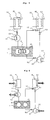
- FIG. 7 illustrates the parts of the device for producing refrigeration of Example 2 that are active during the refrigeration production step.
- FIG. 8 illustrates the parts of the device for producing refrigeration of Example 2 that are active during the regeneration step.
- FIG. 9 provides the equilibrium curves of the thermochemical phenomena for the operation of the device of Example 1.
- FIG. 10 provides the equilibrium curves of the thermochemical phenomena for the operation of the device of Example 2.
- the device for producing refrigeration according to the present invention comprises a refrigeration-producing dipole D 2 and an auxiliary dipole D 1 , and it is characterized in that:
- the expressions “the elements” of a dipole will be used to denote both the reactor and the evaporator/condenser of the dipole.
- thermochemical phenomena used in the present invention mention may be made of the L/G phase change of ammonia (NH 3 ), of methylamine (NH 2 CH 3 ) or of H 2 O in the evaporators/condensers.
- NH 3 ammonia
- NH 2 CH 3 methylamine
- H 2 O H 2 O
- the method for producing refrigeration at the temperature T f from a heat source at the temperature T h and from a heat sink at the ambient temperature T o consists in operating the device according to the invention from an initial state in which the dipole D 2 is in the regenerated state, and the dipole D 1 is to be regenerated, the two elements of a given dipole being isolated from one another, said method comprising a series of successive cycles made up of a refrigeration production step and a regeneration step;
- the dipoles therefore operate in phase opposition: one of the dipoles is in a phase of gas absorption in the sorbent, whereas the other is in a phase of gas desorption by the sorbent.
- the various steps may be carried out continuously or on demand.
- the elements of one and the same dipole must be connected, so that the thermochemical phenomena can occur.
- the device is intended to be operated in batch mode, it is sufficient to isolate the elements of each dipole by insulation means, at the end of a refrigeration production step or a regeneration step.
- the method may be implemented permanently if the heat at the temperature T h is available permanently, for example if it is geothermal energy.
- the operation will be in batch mode if the heat source is not permanent, for example if it is solar energy whose availability varies throughout a day.
- the coupling of the dipoles is carried out thermally between the evaporator/condenser EC 1 of the dipole D 1 and the evaporator/condenser EC 2 of the dipole D 2 , and the thermochemical phenomena are chosen such that, in this coupling phase, T(EC 1 ) ⁇ T(EC 2 ) ⁇ T(R 1 ) ⁇ T(R 2 ). In this case, G 1 and G 2 are different.
- the thermal coupling between EC 1 and EC 2 may be carried out, for example, by a coolant loop, by a heat pipe or by direct contact.
- the method of this first embodiment is characterized in that, during the second step, the evaporators/condensers EC 1 and EC 2 are thermally coupled, and at the same time heat at the temperature T h is supplied to the reactor R 2 to cause the endothermic desorption of G 2 in R 2 and the exothermic condensation of G 2 in EC 2 , the heat generated in EC 2 being transferred to the reactor EC 1 , which causes an endothermic evaporation of G 1 in EC 1 and a concomitant exothermic absorption of G 1 by S 1 in R 1 .
- the device produces refrigeration at the temperature T f during the refrigeration production step of the dipole D 2 concomitant to the regeneration step of the auxiliary dipole D 1 .
- refrigeration may be produced at the temperature T i below T o in EC 1 by the dipole D 1 , if the heat required during this step for the evaporation phase in EC 1 is greater than the heat supplied by the condensation phase in EC 2 .
- FIGS. 1 a and 1 b represent the Clausius-Clapeyron plot respectively for the refrigeration production step ( FIG. 1 a ), and for the regeneration step ( FIG. 1 b ).
- the straight lines 0 , 1 , 2 and 3 represent the equilibrium curve respectively for the L/G phase change of the gas G 1 , the reversible phenomenon G 1 +S 1 ⁇ (G 1 , S 1 ), the reversible phenomenon G 2 +S 2 ⁇ (G 2 , S 2 ) and the L/G phase change of the gas G 2 .
- heat at the temperature T h is supplied to R 2 (point R D2 on the straight line 2 ) which releases gaseous G 2 that will be condensed in EC 2 (point C 2 on the straight line 3 ) by releasing heat at the temperature T i , said heat being transferred toward EC 1 in order to trigger therein the release of gas G 1 (point E 1 on the curve 0 ), said gas G 1 flowing into R 1 for the synthesis step (point R 1S on the curve 1 ). If the heat supplied by EC 2 to EC 1 is insufficient to release all the gas in EC 1 , the heat is extracted from the environment, which will produce refrigeration at the temperature T i below the ambient temperature.
- each of the elements EC is composed of an assembly comprising an evaporator E and a condenser C connected by a line enabling the flow of gas or liquid. Furthermore, in order to limit the heat losses and to improve the efficiency of the regeneration of the dipole D 1 , the elements involved in the thermal coupling, that is to say E 1 and C 2 , are thermally isolated from the ambient medium.
- the two dipoles operate with the same gas G.
- the dipoles D 1 and D 2 of the device according to the invention are coupled, during the regeneration phase of the dipole D 1 , by a mass coupling which allows the flow of gas between the reactor R 1 of the dipole D 1 and the reactor R 2 of the dipole D 2 on the one hand, and between the evaporators/condensers EC 1 and EC 2 on the other hand.
- the method for producing refrigeration according to this second embodiment is characterized in that, at the beginning of the second step, the connection between EC 2 and R 2 is stopped, and R 1 and R 2 are connected, and at the same time heat at the temperature T h is supplied to the reactor R 2 , which causes the endothermic desorption of G by S 2 in R 2 , and by cooling the reactor R 1 , which causes absorption of the gas G in R 1 .
- Cooling may be carried out by using coolant circuits. Cooling may also be controlled by external conditions, for example by natural nighttime cooling, in the absence of the sun.
- EC 1 and EC 2 are connected to make G flow in liquid form from EC 1 toward EC 2 .
- This operation may be carried out during an additional step. It may, in addition, be carried out during the first or the second step, if the device comprises an expansion valve on the line connecting EC 1 and EC 2 .
- FIGS. 2 a and 2 b represent the Clausius-Clapeyron plotrespectively for the refrigeration production step ( FIG. 2 a ), and for the regeneration step ( FIG. 2 b ).
- the straight lines 0 , 1 and 2 represent the equilibrium curve respectively for the L/G phase change of the gas G, the reversible phenomenon G+S 1 ⁇ (G, S 1 ), and the reversible phenomenon G+S 2 ⁇ (G, S 2 ).
- This example illustrates a device for producing refrigeration, in which the dipoles interact by a thermal coupling.
- Each of the elements EC is composed of a condenser and an evaporator connected by a line enabling the flow of gas or liquid, and denoted by C 1 , C 2 , E 1 and E 2 .
- a schematic representation of the device is given in FIG. 3 .
- the dipole D 1 comprises a reactor R 1 , a condenser C 1 and an evaporator E 1 .
- R 1 and C 1 are connected by a line equipped with a valve 1 . 1
- C 1 and E 1 are connected by a single line.
- R 1 is equipped with heating means 2 . 1 and means 3 . 1 for extracting heat.
- C 1 is equipped with means 4 . 1 for extracting the heat of condensation.
- the dipole D 2 comprises a reactor R 2 , a condenser C 2 and an evaporator E 2 .
- R 2 and C 2 are connected by a line equipped with a valve 1 . 2
- R 2 and E 2 are connected by a line equipped with a valve 8 .
- E 2 is connected by a line equipped with an expansion valve 9 . 2 .
- R 2 is equipped with heating means 2 . 2 and means 3 . 2 for removing heat.
- E 2 is equipped with means 5 . 2 for extracting heat from the medium to be cooled.
- E 1 and C 2 are equipped with means 6 enabling heat to be exchanged between them and a device 7 which thermally insulates them from the environment.
- R 1 is the site of a reversible chemical sorption of methylamine (gas G 1 ) on CaCl 2 .2NH 2 CH 3 (the reactive solid S 1 ), C 1 and E 1 being the site of a condensation/evaporation phenomenon of methylamine (the gas G 1 ).
- R 2 is the site of a reversible chemical sorption of NH 3 (the gas G 2 ) on CaCl 2 .4NH 3 (the solid S 2 ), C 2 and E 2 being the site of a condensation/evaporation phenomenon of the gas NH 3 .
- thermochemical phenomena are as follows:
- FIG. 9 The operation of the device comprising these reactants is represented in FIG. 9 , which gives the equilibrium curves of the thermochemical phenomena in question.
- FIG. 4 The parts of the device that are active during the refrigeration production step are represented in FIG. 4 .
- the valves 1 . 1 and 1 . 2 are opened and the heat transfer means 6 are deactivated. Opening the valves 8 . 2 and 9 . 2 causes the spontaneous production of the gas G 2 in E 2 , the transfer of G 2 toward R 2 and through the valve 8 . 2 , which causes on the one hand the production of refrigeration around E 2 by the means for extracting heat 5 . 2 , and the synthesis in R 2 , with removal of the heat formed toward the atmosphere around R 2 using the means 3 . 2 . At the same time, the heating means 2 .
- the parts of the devices that are active during the regeneration step of the device are represented in FIG. 5 .
- the valves 1 . 1 and 1 . 2 remain open, R 2 is supplied with heat at the temperature T h by the means 2 . 2 , which releases the gas G 2 that flows into the condenser C 2 in which it is condensed before flowing simultaneously or subsequently into the evaporator E 2 , depending on the state of the valve 9 . 2 .
- the heat released by the condensation in C 2 is transferred toward E 1 by the means 6 .
- This supply of heat in E 1 causes an evaporation of G 1 which is transferred via C 1 and the valve 1 .
- the device is again ready to produce refrigeration. If the production must be immediate, the first step is restarted. If the production must be deferred, the device is kept in the regenerated state by closing the valves 1 . 1 , 1 . 2 and 8 . 2 .
- Such a device enables refrigeration to be produced at a temperature T i halfway between T o and T f during the regeneration step of the device. For example, referring to FIG. 9 , if the heat supplied by EC 2 by the condensation of NH 3 to EC 1 for the evaporation of NH 2 CH 3 is insufficient to release all the NH 2 CH 3 , heat is extracted from the environment, which will produce refrigeration at the temperature T i around 0° C.
- This example illustrates a device for producing refrigeration, in which the dipoles interact by mass coupling.
- EC 1 and EC 2 are respectively a condenser C 1 and an evaporator E 2 .
- a schematic representation of the device is given in FIG. 6 .
- the dipole D 1 comprises the reactor R 1 and the condenser C 1 connected by a line equipped with a valve 11 .
- R 1 comprises means 21 for introducing heat and means 31 for removing heat.
- C 1 comprises means 41 for removing heat.
- the dipole D 2 comprises the reactor R 2 and the evaporator E 2 connected by a line equipped with a valve 12 .
- R 2 comprises means 22 for introducing heat and means 32 for removing heat.
- E 2 comprises means 52 for supplying heat.
- R 1 and R 2 are connected by a line which is placed before the valves 11 and 12 , and which is equipped with a valve 8 .
- C 1 is connected by a line to a reservoir which is itself connected to E 2 by a line equipped with an expansion valve 9 which may be, for example, controlled and activated by a drop in the pressure or liquid level in E 2 .
- the active parts of the device during the refrigeration production step are represented in FIG. 7 .
- the valve 8 is closed, the expansion valve 9 is activated depending on the liquid level or the pressure in E 2 , and the valves 11 and 12 are opened. Opening the valve 12 causes the exothermic evaporation of gas in E 2 with production of refrigeration, and the exothermic synthesis in R 2 , the heat being extracted by 32.
- R 1 is supplied with heat at the temperature T f via 21, which causes the release of gas in R 1 , the transfer of this gas toward C in which it condenses, the heat of condensation being transferred toward the environment by 41.
- the condensed liquid in C is transferred into the reservoir 10 .
- FIG. 8 The active parts of the device during the regeneration step are represented in FIG. 8 .
- the valves 11 and 12 are closed, the valve 8 is opened and the expansion valve 9 is closed, considering the fact that the pressure or the liquid level in E 2 have not decreased.
- a supply of heat at the temperature T f to R 2 via 22 causes a release of gas in R 2 , the transfer of this gas toward R 1 via the valve 8 , and the exothermic synthesis in R 1 , the heat released being removed via 31.
- Such a device may be implemented using ammonia as gas G, CaCl 2 .4NH 3 as solid S 2 in R 2 and BaCl 2 as solid S 1 in R 1 .
- thermochemical phenomena are as follows: NH 3(gas) ⁇ NH 3(liquid) (CaCl 2 .4NH 3 )+4NH 3 ⁇ (CaCl 2 .8NH 3 ) (BaCl 2 )+8NH 3 ⁇ (BaCl 2 8NH 3 )
- FIG. 10 The operation of the device comprising these reactants is represented in FIG. 10 , which gives the equilibrium curves of the thermochemical phenomena in question. Similar curves would be obtained with a similar device, in which CaCl 2 .4NH 3 would be replaced with SrCl 2 .NH 3 .
- the refrigeration production step is embodied by the positions 1 and 2 of the dipoles D 1 and D 2 .
- D 2 is in refrigeration production phase, extracting heat from the medium to be cooled to a temperature T f of around ⁇ 30° C.
- the regeneration step of D 2 is embodied by the position 3 .
- the supply of the available heat at the temperature T h of around 70° C. causes the decomposition of (CaCl 2 .8NH 3 ) releasing NH 3 , which is transferred into R 1 to cause therein the synthesis of BaCl 2 .8NH 3 .
- the reactors R 1 and R 2 are in the state required for a regenerated device, and the opening of the valve 9 enables C 1 and E 2 to be put into the required state for complete regeneration of the device.
Landscapes
- Engineering & Computer Science (AREA)
- Physics & Mathematics (AREA)
- Mechanical Engineering (AREA)
- Thermal Sciences (AREA)
- General Engineering & Computer Science (AREA)
- Sorption Type Refrigeration Machines (AREA)
- Solid-Sorbent Or Filter-Aiding Compositions (AREA)
Applications Claiming Priority (3)
| Application Number | Priority Date | Filing Date | Title |
|---|---|---|---|
| FR0411766 | 2004-11-04 | ||
| FR0411766A FR2877426B1 (fr) | 2004-11-04 | 2004-11-04 | Production de froid a tres basse temperature dans un dispositif thermochimique. |
| PCT/FR2005/002748 WO2006048558A1 (fr) | 2004-11-04 | 2005-11-04 | Production de froid a tres basse temperature dans un dispositif thermochimique. |
Publications (2)
| Publication Number | Publication Date |
|---|---|
| US20090094996A1 US20090094996A1 (en) | 2009-04-16 |
| US8327660B2 true US8327660B2 (en) | 2012-12-11 |
Family
ID=34953523
Family Applications (1)
| Application Number | Title | Priority Date | Filing Date |
|---|---|---|---|
| US11/666,926 Active 2028-08-16 US8327660B2 (en) | 2004-11-04 | 2005-11-04 | Production of very low-temperature refrigeration in a thermochemical device |
Country Status (6)
| Country | Link |
|---|---|
| US (1) | US8327660B2 (fr) |
| EP (1) | EP1809955B1 (fr) |
| JP (1) | JP4889650B2 (fr) |
| ES (1) | ES2647901T3 (fr) |
| FR (1) | FR2877426B1 (fr) |
| WO (1) | WO2006048558A1 (fr) |
Families Citing this family (6)
| Publication number | Priority date | Publication date | Assignee | Title |
|---|---|---|---|---|
| CN102066854B (zh) | 2008-06-19 | 2016-07-13 | 索泰克股份公司 | 用于在交替工作的吸附器之间实施热传递的方法及设备 |
| CN101818967B (zh) * | 2010-05-20 | 2012-08-29 | 上海交通大学 | 热化学变温吸附冷热联供复合储能供能装置 |
| GB201402059D0 (en) * | 2014-02-06 | 2014-03-26 | Univ Newcastle | Energy Storage device |
| CN104132476B (zh) * | 2014-07-18 | 2017-02-01 | 上海交通大学 | 低品位热能驱动高效吸湿‑热化学反应单级变温器 |
| CN104110913B (zh) * | 2014-07-18 | 2016-04-13 | 上海交通大学 | 低品位废热驱动高效吸湿-热化学反应双级变温器 |
| FR3034179B1 (fr) * | 2015-03-23 | 2018-11-02 | Centre National De La Recherche Scientifique | Dispositif solaire de production autonome de froid par sorption solide-gaz. |
Citations (8)
| Publication number | Priority date | Publication date | Assignee | Title |
|---|---|---|---|---|
| US4623018A (en) | 1983-07-08 | 1986-11-18 | Matsushita Electric Industrial Co., Ltd. | Thermal system based on thermally coupled intermittent absorption heat pump cycles |
| US4944159A (en) | 1987-05-22 | 1990-07-31 | Faiveley Entreprises | Process for producing cold by solid-gas reaction and device pertaining thereto |
| US5083607A (en) | 1989-10-24 | 1992-01-28 | Societe Nationale Elf Aquitaine | Devices for producing cold and/or heat by solid-gas reaction managed by gravitational heat pipes |
| US5174367A (en) | 1989-03-13 | 1992-12-29 | Sanyo Electric Co., Ltd. | Thermal utilization system using hydrogen absorbing alloys |
| US5351493A (en) | 1991-12-10 | 1994-10-04 | Sanyo Electric Co., Ltd. | Thermally driven refrigeration system utilizing metal hydrides |
| WO1997040328A1 (fr) | 1996-04-25 | 1997-10-30 | Elf Aquitaine | Dispositif thermochimique pour produire du froid et/ou de la chaleur |
| US5857346A (en) | 1994-10-28 | 1999-01-12 | Elf Aquitaine | Reactant for thermochemical systems and thermochemical system intended to employ such a reactant |
| WO2005108880A1 (fr) * | 2004-05-11 | 2005-11-17 | Cyclect Singapore Pte Ltd | Systeme d'adsorption regeneratif |
-
2004
- 2004-11-04 FR FR0411766A patent/FR2877426B1/fr active Active
-
2005
- 2005-11-04 WO PCT/FR2005/002748 patent/WO2006048558A1/fr active Application Filing
- 2005-11-04 US US11/666,926 patent/US8327660B2/en active Active
- 2005-11-04 ES ES05814788.5T patent/ES2647901T3/es active Active
- 2005-11-04 EP EP05814788.5A patent/EP1809955B1/fr active Active
- 2005-11-04 JP JP2007539609A patent/JP4889650B2/ja active Active
Patent Citations (8)
| Publication number | Priority date | Publication date | Assignee | Title |
|---|---|---|---|---|
| US4623018A (en) | 1983-07-08 | 1986-11-18 | Matsushita Electric Industrial Co., Ltd. | Thermal system based on thermally coupled intermittent absorption heat pump cycles |
| US4944159A (en) | 1987-05-22 | 1990-07-31 | Faiveley Entreprises | Process for producing cold by solid-gas reaction and device pertaining thereto |
| US5174367A (en) | 1989-03-13 | 1992-12-29 | Sanyo Electric Co., Ltd. | Thermal utilization system using hydrogen absorbing alloys |
| US5083607A (en) | 1989-10-24 | 1992-01-28 | Societe Nationale Elf Aquitaine | Devices for producing cold and/or heat by solid-gas reaction managed by gravitational heat pipes |
| US5351493A (en) | 1991-12-10 | 1994-10-04 | Sanyo Electric Co., Ltd. | Thermally driven refrigeration system utilizing metal hydrides |
| US5857346A (en) | 1994-10-28 | 1999-01-12 | Elf Aquitaine | Reactant for thermochemical systems and thermochemical system intended to employ such a reactant |
| WO1997040328A1 (fr) | 1996-04-25 | 1997-10-30 | Elf Aquitaine | Dispositif thermochimique pour produire du froid et/ou de la chaleur |
| WO2005108880A1 (fr) * | 2004-05-11 | 2005-11-17 | Cyclect Singapore Pte Ltd | Systeme d'adsorption regeneratif |
Non-Patent Citations (2)
| Title |
|---|
| Imoto, T. et al., "Development of an F-Class Refrigeration System Using Hydrogen-Absorbing Alloys", Int. J. Hydrogen Energy, vol. 21, No. 6, pp. 451-455, 1996, Paris, France, XP000587901. |
| International Search Report dated Mar. 17, 2006 (Three (3) pages). |
Also Published As
| Publication number | Publication date |
|---|---|
| FR2877426B1 (fr) | 2007-03-02 |
| WO2006048558A1 (fr) | 2006-05-11 |
| US20090094996A1 (en) | 2009-04-16 |
| EP1809955B1 (fr) | 2017-08-16 |
| ES2647901T3 (es) | 2017-12-27 |
| JP4889650B2 (ja) | 2012-03-07 |
| JP2008519239A (ja) | 2008-06-05 |
| FR2877426A1 (fr) | 2006-05-05 |
| EP1809955A1 (fr) | 2007-07-25 |
Similar Documents
| Publication | Publication Date | Title |
|---|---|---|
| JP3159448B2 (ja) | 二重温度熱ポンプ装置およびシステム | |
| US8327660B2 (en) | Production of very low-temperature refrigeration in a thermochemical device | |
| US4055962A (en) | Hydrogen-hydride absorption systems and methods for refrigeration and heat pump cycles | |
| JP2664506B2 (ja) | 固体―気体間反応による冷却および/または加熱装置 | |
| KR102543809B1 (ko) | 에너지의 열화학적 저장 시스템 및 방법 | |
| Boubakri | A new conception of an adsorptive solar-powered ice maker | |
| CN107606816B (zh) | 低品位热驱动吸附式化学反应制冷热泵循环装置及方法 | |
| Vasil’ev et al. | Multisalt-carbon chemical cooler for space applications | |
| US20090199578A1 (en) | Production of Very Low-Temperature Refrigeration in a Thermochemical Device | |
| US5964097A (en) | Thermochemical device for producing cold and/or heat | |
| Li et al. | A conceptual design and performance analysis of a triple-effect solid–gas thermochemical sorption refrigeration system with internal heat recovery | |
| US20110126552A1 (en) | Producing Cold by a Thermochemical Method for Air-Conditioning a Building | |
| US7100398B2 (en) | Installation and method for producing cold or heat using a sorption system | |
| USRE30840E (en) | Hydrogen-hydride absorption systems and methods for refrigeration and heat pump cycles | |
| JP6061462B2 (ja) | 化学蓄熱装置 | |
| Li et al. | High-efficient thermochemical sorption refrigeration driven by low-grade thermal energy | |
| JPH06109388A (ja) | ケミカル蓄熱方法及び装置 | |
| EP3184932B1 (fr) | Tube composite à adsorption pour collecte de chaleur solaire, lit composite à adsorption pour collecte de chaleur solaire composé de tubes composites à adsorption pour collecte de chaleur solaire, et système de refroidissement et de chauffage formé du lit composite à adsorption pour collecte de chaleur solaire | |
| CN117704672A (zh) | 一种热化学储热和空气源热泵耦合系统及其运行方法 | |
| JPH0268463A (ja) | ケミカルヒートポンプ | |
| Vasiliev Jr et al. | Resorption Heat Pumps—Energy Saving Technology | |
| Vasiliev | Heat pumps and heat pipes for applications in cold regions | |
| JPH05288485A (ja) | 排熱昇温回収装置 | |
| JPS61134551A (ja) | 金属水素化物ヒ−トポンプ装置 | |
| JPH0126461B2 (fr) |
Legal Events
| Date | Code | Title | Description |
|---|---|---|---|
| AS | Assignment |
Owner name: CENTRE NATIONAL DE LA RECHERCHE SCIENTIFIQUE, FRAN Free format text: ASSIGNMENT OF ASSIGNORS INTEREST;ASSIGNORS:STITOU, DRISS;MAZET, NATHALIE;SPINNER BROSSARD, CAROLINE;AND OTHERS;REEL/FRAME:021717/0351;SIGNING DATES FROM 20070702 TO 20070919 Owner name: CENTRE NATIONAL DE LA RECHERCHE SCIENTIFIQUE, FRAN Free format text: ASSIGNMENT OF ASSIGNORS INTEREST;ASSIGNORS:STITOU, DRISS;MAZET, NATHALIE;SPINNER BROSSARD, CAROLINE;AND OTHERS;SIGNING DATES FROM 20070702 TO 20070919;REEL/FRAME:021717/0351 |
|
| STCF | Information on status: patent grant |
Free format text: PATENTED CASE |
|
| FPAY | Fee payment |
Year of fee payment: 4 |
|
| MAFP | Maintenance fee payment |
Free format text: PAYMENT OF MAINTENANCE FEE, 8TH YEAR, LARGE ENTITY (ORIGINAL EVENT CODE: M1552); ENTITY STATUS OF PATENT OWNER: LARGE ENTITY Year of fee payment: 8 |