US822971A - Valve-adjuster for oil-wells. - Google Patents
Valve-adjuster for oil-wells. Download PDFInfo
- Publication number
- US822971A US822971A US29563306A US1906295633A US822971A US 822971 A US822971 A US 822971A US 29563306 A US29563306 A US 29563306A US 1906295633 A US1906295633 A US 1906295633A US 822971 A US822971 A US 822971A
- Authority
- US
- United States
- Prior art keywords
- adjuster
- valve
- oil
- screw
- wells
- Prior art date
- Legal status (The legal status is an assumption and is not a legal conclusion. Google has not performed a legal analysis and makes no representation as to the accuracy of the status listed.)
- Expired - Lifetime
Links
Images
Classifications
-
- F—MECHANICAL ENGINEERING; LIGHTING; HEATING; WEAPONS; BLASTING
- F16—ENGINEERING ELEMENTS AND UNITS; GENERAL MEASURES FOR PRODUCING AND MAINTAINING EFFECTIVE FUNCTIONING OF MACHINES OR INSTALLATIONS; THERMAL INSULATION IN GENERAL
- F16C—SHAFTS; FLEXIBLE SHAFTS; ELEMENTS OR CRANKSHAFT MECHANISMS; ROTARY BODIES OTHER THAN GEARING ELEMENTS; BEARINGS
- F16C7/00—Connecting-rods or like links pivoted at both ends; Construction of connecting-rod heads
- F16C7/06—Adjustable connecting-rods
-
- Y—GENERAL TAGGING OF NEW TECHNOLOGICAL DEVELOPMENTS; GENERAL TAGGING OF CROSS-SECTIONAL TECHNOLOGIES SPANNING OVER SEVERAL SECTIONS OF THE IPC; TECHNICAL SUBJECTS COVERED BY FORMER USPC CROSS-REFERENCE ART COLLECTIONS [XRACs] AND DIGESTS
- Y10—TECHNICAL SUBJECTS COVERED BY FORMER USPC
- Y10T—TECHNICAL SUBJECTS COVERED BY FORMER US CLASSIFICATION
- Y10T74/00—Machine element or mechanism
- Y10T74/21—Elements
- Y10T74/2142—Pitmans and connecting rods
- Y10T74/2151—Longitudinally adjustable
Definitions
- This invention relates to adjusters for the .valve of oil-well pumps, and has for an object to provide a device of the class embodying new and improved features of convenience, durability, economy, and efficiency.
- a further object of the invention is to provide a device of the class embodying improved means for fastening to a walkingbeam or j ack-arm.
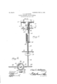
- Figure 1 is a view of the improved adjuster in side elevation with part of the tube broken away to show the operation and disposition of the adjusting-screw.
- Fig. 2 is a transverse sectional view taken on line 2 2 of Fig. 1.
- the improved adjusting device forming the subject-matter of this application comprises a tube 10, provided at its upper end w1th the walking-beam engaging the cross-head 11 and lifting-eye 12. At its lower end the tube is provided with a rigidly-secured block 13, bored axially to the tube and screw-threaded to engage the adjusting-screw 14.
- the screw 14 is provided with handle-bars 15, by which it may be rotated, and a set-screw 16 is inserted through the block 13 to engage the screw 14.
- the split sleeve 20 Upon the tu e 10 is slidably mounted the split sleeve 20, having outstanding ears 21 and 22, through which is inserted a clamping-bolt 23, provided with a tension-nut 24.
- handle-bars 25 and 26 Upon the sleeve, and diametrically extended therefrom, are handle-bars 25 and 26 for engaging a j ack-arm for pumping.
- a device of the character described comprising an arm-engaging cross-head, a tube extending from the cross-head, an internallyscrew-threaded block secured within one end of the tube, a clamp adjustably mounted on the tube, arms radiating therefrom, a threaded stem engaging the block and extending into the tube, means extending through the block and tube for binding the stem to hold it against rotation, a polish-rod, a link adjustably connected thereto and swiveled on the stem, arms radiating from the stem, and means extending through the link for binding upon the stem to hold the link and stem against rotation.
Description
No. 822,97l. PATENTED JUNE 12, 1906, E. E. MATTHEWS.
VALVE ADJUSTER EOE OIL WELLS.
APPLICATION FILED JAN.11,1906.
INVENTOR A TTORNE VS UNITED STATES PATENT OFFICE.
Specification of Letters Patent.
Patented June 12, 1906.
Application filed January 11, 1906. Serial No. 295,633-
To all whom it may concern:
Be it known that I, ELMER RAYMOND MAT- THEWS, a citizen of the United States, residing at Hohman, in the county of Washington and State of Ohio, have invented a new and useful Valve-Adjuster for Oil-Wells, of which the following is a specification.
This invention relates to adjusters for the .valve of oil-well pumps, and has for an object to provide a device of the class embodying new and improved features of convenience, durability, economy, and efficiency.
A further object of the invention is to provide a device of the class embodying improved means for fastening to a walkingbeam or j ack-arm.
With these and other objects in view the present invention consists in the combination and arrangement of parts, as will be hereinafter fully described, shown in the accompanying drawings, and particularly pointed out in the appended claim, it being understood that changes in the form, proportion, size, and minor details may be made without departing from the spirit or sacrificing any of the advantages of this invention.
In the drawings, Figure 1 is a view of the improved adjuster in side elevation with part of the tube broken away to show the operation and disposition of the adjusting-screw. Fig. 2 is a transverse sectional view taken on line 2 2 of Fig. 1.
Like characters of reference indicate corresponding parts inboth figures of the drawings.
In its preferred embodiment the improved adjusting device forming the subject-matter of this application comprises a tube 10, provided at its upper end w1th the walking-beam engaging the cross-head 11 and lifting-eye 12. At its lower end the tube is provided with a rigidly-secured block 13, bored axially to the tube and screw-threaded to engage the adjusting-screw 14. The screw 14 is provided with handle-bars 15, by which it may be rotated, and a set-screw 16 is inserted through the block 13 to engage the screw 14.
Upon the lower end of the screw 14 is swiveled the link 17, in which the polish-rod 18 is rigidly secured, and a set-screw 19 is inserted in the link 17 to engage the screw 14 and hold the screw and olish-rod in rigid alinement.
Upon the tu e 10 is slidably mounted the split sleeve 20, having outstanding ears 21 and 22, through which is inserted a clamping-bolt 23, provided with a tension-nut 24.
Upon the sleeve, and diametrically extended therefrom, are handle-bars 25 and 26 for engaging a j ack-arm for pumping.
From the foregoing description it is believed the use, operation, and advantages of the improved valve-adjuster will be clearly understood and fully ap reciated.
Having thus describe the invention, what is claimed is A device of the character described, comprising an arm-engaging cross-head, a tube extending from the cross-head, an internallyscrew-threaded block secured within one end of the tube, a clamp adjustably mounted on the tube, arms radiating therefrom, a threaded stem engaging the block and extending into the tube, means extending through the block and tube for binding the stem to hold it against rotation, a polish-rod, a link adjustably connected thereto and swiveled on the stem, arms radiating from the stem, and means extending through the link for binding upon the stem to hold the link and stem against rotation.
In testimony that I claim the foregoing as my own I have hereto affixed my signature in the presence of two witnesses.
I ELMER RAYMOND MATTHEWS Witnesses:
S. F. JOY, R. L. HANLON.
Priority Applications (1)
| Application Number | Priority Date | Filing Date | Title |
|---|---|---|---|
| US29563306A US822971A (en) | 1906-01-11 | 1906-01-11 | Valve-adjuster for oil-wells. |
Applications Claiming Priority (1)
| Application Number | Priority Date | Filing Date | Title |
|---|---|---|---|
| US29563306A US822971A (en) | 1906-01-11 | 1906-01-11 | Valve-adjuster for oil-wells. |
Publications (1)
| Publication Number | Publication Date |
|---|---|
| US822971A true US822971A (en) | 1906-06-12 |
Family
ID=2891450
Family Applications (1)
| Application Number | Title | Priority Date | Filing Date |
|---|---|---|---|
| US29563306A Expired - Lifetime US822971A (en) | 1906-01-11 | 1906-01-11 | Valve-adjuster for oil-wells. |
Country Status (1)
| Country | Link |
|---|---|
| US (1) | US822971A (en) |
-
1906
- 1906-01-11 US US29563306A patent/US822971A/en not_active Expired - Lifetime
Similar Documents
| Publication | Publication Date | Title |
|---|---|---|
| US1802499A (en) | Hose clamp | |
| US822971A (en) | Valve-adjuster for oil-wells. | |
| US300501A (en) | Stop-cock clamp | |
| US368408A (en) | Clutch-clamp | |
| US712486A (en) | Antifriction device for sucker-rods. | |
| US789994A (en) | Clamp for pump-rods. | |
| US787621A (en) | Adjuster for deep-well sucker-rods. | |
| US448573A (en) | Thomas g | |
| US778163A (en) | Pump-stand. | |
| US210618A (en) | Improvement in rod-adjusters for oil-wells | |
| US1212962A (en) | Swivel-socket for oil and gas well drills. | |
| US1270538A (en) | Swivel connection. | |
| US898377A (en) | Combined stop and check. | |
| US266365A (en) | Adjustable piston-packing | |
| US196564A (en) | Improvement in sucker-rod adjusters | |
| US643972A (en) | Adjustable pump. | |
| US445100A (en) | Mordecai turtox | |
| US1083858A (en) | Rod-clamp. | |
| US1071360A (en) | Packing-head for deep wells. | |
| US1409022A (en) | Swivel for pipes | |
| US244151A (en) | Apparatus for pumping artesian wells | |
| US196231A (en) | Improvement in pump-rod adjusters for oil-wells | |
| US192048A (en) | Improvement in adjusting-clamps | |
| US297456A (en) | Book drills | |
| US858647A (en) | Oil and water well valve. |