CROSS-REFERENCE TO RELATED APPLICATIONS
This patent application claims the benefit of, under Title 35, United States Code, Section 119(e), U.S. Provisional Patent Application No. 60/871,691, filed Dec. 22, 2006.
FIELD OF THE INVENTION
The present invention relates generally to the field of electrical discharge machining (“EDM machining”), and more particularly to a system and method which incorporates ultrasonics to assist in the formation of parts, such as turbine blades, using EDM machining.
BACKGROUND OF THE INVENTION
The machining of small holes in an alloy steel turbine blade is often currently being done using an EDM machining process, in which the electrolyte used is typically deionized water (DI water). While such process provides several advantages over other known alternatives, as is known, the process can be quite slow. For example, in a typical turbine blade, there are as many as 50-100 holes required for each blade, and the time required to drill them is quite long. However, it has been shown that when ultrasonic energy is added to an EDM machining process the speed of material removal is increased. Therefore, applying ultrasonic energy to the turbine blade reduces the EDM machining time.
However, the problem exists as to how to efficiently couple ultrasonic energy to the blade. One alternative is to clamp the blade to the face of a half wavelength resonant horn. However, this is a very difficult task to accomplish because the combination of the horn, blade and clamp must sustain the ultrasonic vibrations. Problematically, the forces from the ultrasonic vibration tend to shake the clamp and horn apart after only a few seconds of operation.
Another alternative to vibrate the blade is to place the blade in a cavity machined into the horn face and pour epoxy into the cavity in order to hold the blade in place after the epoxy is cured. However, this requires that the horn, blade and epoxy all have to be at a set resonant frequency, which is not easily accomplished. Also, after one is finished with the machining operation the epoxy must be removed, also not an easy task to accomplish.
A more effective method of coupling the blade to the horn is to first determine the resonant half wavelength of the blade and directly drive it with a matching horn of the same frequency. However, the problem still exists as to how to attach the blade to the horn. The present invention addresses this problem.
SUMMARY OF THE INVENTION
More specifically, in accordance with a first aspect of the present invention, a system for ultrasonic assisted electrical discharge machining of a component part having a longitudinal axis, a half wavelength resonant frequency along the longitudinal axis and an attachment portion, is provided. The system includes an ultrasonic horn having a longitudinal axis, a half wavelength resonant frequency along the longitudinal axis and an attachment portion. The half wavelength resonant frequency of the ultrasonic horn is the same as the half wavelength resonant frequency of the component part. Additionally, one of the attachment portion of the component part and the attachment portion of the ultrasonic horn comprises a male part and the other one of the attachment portion of the component part and the attachment portion of the ultrasonic horn comprises a female part sized and shaped to mate and engage one another when the component part and the ultrasonic horn are at generally the same temperature.
In some embodiments, the female part has generally the same shape as and smaller dimensions than the male part when the component part and the ultrasonic horn are at generally the same temperature.
In some embodiments, the one of the component part and the ultrasonic horn whose attachment portion comprises the female part is formed of a material having a greater coefficient of thermal expansion than does the one of the component part and the ultrasonic horn whose attachment portion comprises the male part. In certain of these embodiments, the attachment portion of the component part comprises the male part and the attachment portion of the ultrasonic horn comprises the female part. In certain of these embodiments, the component part comprises a turbine blade and the male part comprises a tang. In certain embodiments, the component part is formed from steel and the ultrasonic horn is formed from titanium or aluminum.
In some embodiments, the attachment portion of the component part is disposed along the longitudinal axis of the component part. In certain of these embodiments, the attachment portion of the ultrasonic horn is disposed along the longitudinal axis of the ultrasonic horn. In certain of these embodiments, the longitudinal axis of the component part and the longitudinal axis of the ultrasonic horn are coaxial.
In some embodiments, the system further includes a source of ultrasonic energy which imparts ultrasonic vibrations to the ultrasonic horn.
In accordance with another aspect of the present invention, a method for ultrasonic assisted electrical discharge machining comprises the steps of: (i) providing a component part having a longitudinal axis, a half wavelength resonant frequency along the longitudinal axis and an attachment portion; (ii) providing an ultrasonic horn having a longitudinal axis, a half wavelength resonant frequency along the longitudinal axis and an attachment portion, wherein the half wavelength resonant frequency of the ultrasonic horn is the same as the half wavelength resonant frequency of the component part, and wherein one of the attachment portion of the component part and the attachment portion of the ultrasonic horn comprises a male part and the other one of the attachment portion of the component part and the attachment portion of the ultrasonic horn comprises a female part sized and shaped to mate and engage one another when the component part and the ultrasonic horn are at generally the same temperature; (iii) mating the male part and the female part together to join the component part and the ultrasonic horn; and (iv) ultrasonically vibrating the ultrasonic horn and the component part joined thereto at the half wavelength resonant frequency of the ultrasonic horn and the component part.
In some embodiments, the female part has generally the same shape as and smaller dimensions than the male part when the component part and the ultrasonic horn are at generally the same temperature.
In some embodiments, the one of the component part and the ultrasonic horn whose attachment portion comprises the female part is formed of a material having a greater coefficient of thermal expansion than does the one of the component part and the ultrasonic horn whose attachment portion comprises the male part, and the mating step comprises the steps of: (a) heating the component part and the ultrasonic horn such that the female part expands to a greater extent that the male part expands; (b) fitting the male part into the female part; and (c) cooling the component part and the ultrasonic horn such that the female part and the male part shrink such that the male part is engaged within the female part.
In certain of these embodiments, the attachment portion of the component part comprises the male part and wherein the attachment portion of the ultrasonic horn comprises the female part. In certain embodiments, the component part comprises a turbine blade and the male part comprises a tang. In certain embodiments, the component part is formed from steel and the ultrasonic horn is formed from titanium or aluminum.
In some embodiments, the attachment portion of the component part is disposed along the longitudinal axis of the component part. In certain of these embodiments, the attachment portion of the ultrasonic horn is disposed along the longitudinal axis of the ultrasonic horn. In certain embodiments, the longitudinal axis of the component part and the longitudinal axis of the ultrasonic horn are coaxial.
In some embodiments, the step of ultrasonically vibrating the ultrasonic horn is performed by a source of ultrasonic energy which imparts ultrasonic vibrations to the ultrasonic horn.
The invention and its particular features and advantages will become more apparent from the following detailed description considered with reference to the accompanying drawings.
BRIEF DESCRIPTION OF THE DRAWINGS
FIG. 1 is a schematic view of a component part, particularly a turbine blade, in connection with which the system of the present invention may be used for ultrasonic assisted electrical discharge machining.
FIG. 2 is a schematic view of an ultrasonic horn portion of the system for ultrasonic assisted electrical discharge machining of the present invention.
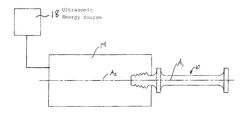
FIG. 3 is a schematic view of the component part of FIG. 1 joined with the ultrasonic horn of FIG. 2, as well as additional portions of the system for ultrasonic assisted electrical discharge machining of the present invention.
DETAILED DESCRIPTION OF THE INVENTION
The present invention stems from the fact that every turbine blade 10 (shown schematically in FIG. 1) has tangs 12 at one end that are used to attach it to a rotating shaft (not shown) after manufacture of the blade 10. Applicant has discovered that attachment of the blade 10 to a horn can be accomplished by making a horn 14 (shown schematically in FIG. 2) having the same resonant frequency as the turbine blade 10 with slightly smaller mating female tangs 16, as compared to the male tangs 14 of the blade 12, which are then heated to capture the tangs 12 of the blade 10 by fitting the blade 10 at the output end of the horn 14.
The horn 14 may be made from either titanium or aluminum, for example, since both of these metals have a greater coefficient of expansion than the steel turbine blades 10. To accomplish the inventive attachment method, the horn 14 is heated up to expand the mating section thereof (i.e., the female tangs 16) so that the mating section of the blade 10 (i.e., the male tangs 12) can be slipped into place, and then the horn 14 is cooled to get a shrink fit on the turbine tangs 12 (as shown schematically in FIG. 3). This holds the blade 10 in place during the machining operation.
After machining, heating the horn 14 expands the horn 14 and allows the blade 10 to be easily removed. All of the methods described would typically involve the blade 10 and horn 14 being submerged in DI water.
Preferably, the blade 10 has a longitudinal axis A1, and the horn 14 has a longitudinal axis A2. Most preferably, the male tang 12 of the blade 10 is disposed along the longitudinal axis A1 of the blade 10, and the female tang 16 of the horn 14 is disposed along the longitudinal axis A2 of the horn 14. It is also preferable if the longitudinal axis A1 of the blade 10 and the longitudinal axis A2 of the horn 14 are coaxial when the two are joined (as shown in FIG. 3).
As will be immediately recognized by those skilled in the art, the system further includes a source of ultrasonic energy 18 which imparts ultrasonic vibrations to the horn 14 (also as shown schematically in FIG. 3).
Although the invention has been described with reference to a particular arrangement of parts, features and the like, these are not intended to exhaust all possible arrangements or features, and indeed many other modifications and variations will be ascertainable to those of skill in the art. For example, although the component part is described above as being a blade 10, the system of the present invention could readily be adapted to work with various other component parts.