US809889A - Churn. - Google Patents
Churn. Download PDFInfo
- Publication number
- US809889A US809889A US27463305A US1905274633A US809889A US 809889 A US809889 A US 809889A US 27463305 A US27463305 A US 27463305A US 1905274633 A US1905274633 A US 1905274633A US 809889 A US809889 A US 809889A
- Authority
- US
- United States
- Prior art keywords
- churn
- uprights
- dasher
- cranks
- rods
- Prior art date
- Legal status (The legal status is an assumption and is not a legal conclusion. Google has not performed a legal analysis and makes no representation as to the accuracy of the status listed.)
- Expired - Lifetime
Links
Images
Classifications
-
- F—MECHANICAL ENGINEERING; LIGHTING; HEATING; WEAPONS; BLASTING
- F04—POSITIVE - DISPLACEMENT MACHINES FOR LIQUIDS; PUMPS FOR LIQUIDS OR ELASTIC FLUIDS
- F04B—POSITIVE-DISPLACEMENT MACHINES FOR LIQUIDS; PUMPS
- F04B9/00—Piston machines or pumps characterised by the driving or driven means to or from their working members
- F04B9/02—Piston machines or pumps characterised by the driving or driven means to or from their working members the means being mechanical
-
- Y—GENERAL TAGGING OF NEW TECHNOLOGICAL DEVELOPMENTS; GENERAL TAGGING OF CROSS-SECTIONAL TECHNOLOGIES SPANNING OVER SEVERAL SECTIONS OF THE IPC; TECHNICAL SUBJECTS COVERED BY FORMER USPC CROSS-REFERENCE ART COLLECTIONS [XRACs] AND DIGESTS
- Y10—TECHNICAL SUBJECTS COVERED BY FORMER USPC
- Y10T—TECHNICAL SUBJECTS COVERED BY FORMER US CLASSIFICATION
- Y10T74/00—Machine element or mechanism
- Y10T74/18—Mechanical movements
- Y10T74/18056—Rotary to or from reciprocating or oscillating
- Y10T74/18208—Crank, pitman, and slide
Definitions
- Our invention relates to flasher-churns in which the dashers are actuated up and down by cranks and pitrnen.
- the invention consists of a flasher-churn in which the dashers are operated vertically by two half-round rods passing through a round hole in the top of the churn.
- Two slotted uprights rest on the top of the churn, and a head-block is arranged between the tops of the uprights, which with the top ends of the uprights torni a hearing for the cranks which are connected with the dasher-rods through the medium of pitinen.
- the dashers are half-round, and one is carried by each rod.
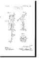
- Figure l shows a front view of the improvements, the churn-body being omitted.
- Eig. 2 is a side elevation.
- Fig. 3 is a bottom view, the cranks and pitmen being omitted.
- F designates the top or head of the churn, from which there extend two uprights A, slotted, as at a, from near the bottom to near the top.
- the standards are spaced by a substantial block I, which with the upper ends of the uprights have a groove formed therein for the straight connecting part of the two cranks C to lie in as a bearing.
- the block I may be made in two parts, as shown, each part being securely bolted to its upright. This secures a iirm construction at the top and enables us to operate the cranks and pitmen outside of the uprights and their bearings.
- C C designate the cranks by which the machine is driven, there being one on each side and the straight connecting part resting in a bearing on the upper ends ofthe uprights and blocks.
- each half-round rod D is secured to one part of the dasher E, which is halfround, so that when the inner sides are brought together the dasher will be a round disk with holes made therethrough, just as it should be to constitute a good dasher-agitator in a round churn.
- the lower ends of the pitmen are connected to the upper ends of the dasher-rods through the intervention of two slides G, grooved on their inner sides to fit the uprights, one being adapted to slide on the outside of its upright and the other on the inside, the two being joined by a screw or bolt and nut I-I.
- the lower end of each pitman B is pivoted, and the upper end of the dasher-rod D is connected to the inner slide-block, the construction being the same on each side.
- the bolt I-I which connects the two slide-blocks, is used also to clamp the upper end oi the dasher-rod D to the block.
- the construction at this point secures an easy operation of the cranks and pitmen and a positive unvarying action of the dasher-rods.
- the churn-body may be made of wood or other material in any shape and of any strength that may be thought best. It constitutes no part of our invention, and hence has not been shown. It may be noted, however, as a mere suggestion that it may consist ot a kind of barrel, the dashers operating through the end, as is common, and the barrel may, if ⁇ thought best, be made larger at the bottoin than at the top.
- the cranks on the outside of the uprights, provided with a straight part having its bearing in the said head blocks, the dasher-rods vertically movable inside of the uprights, the pitmen connected to the cranks, and slide-blocks on the uprights through the intervention of which the pitInen are connected to the dasher-rods.
Landscapes
- Engineering & Computer Science (AREA)
- Mechanical Engineering (AREA)
- General Engineering & Computer Science (AREA)
- Fencing (AREA)
Description
PATENTED JAN. 9, 1906.
No. 809,889.V
D. AYERS 5: J. D. SLOAN.
CHURN.
APPLIGATION FILED AUG.17, 1905.
Ell@
wi busses:
@uA/Md@ Gitana# TINTTED STATES PATENT OTTETCEe DEE AYERS AND JAMES DANIEL SLOAN, OF MOUNT VERNON, MISSOURI.
CHURN.
Specification of Letters Patent.
Patented Jan. 9, 1906.
T0 all wir/0771, t may concern:
Be it known that we, DEE AYERs and Janus DANIEL SLoaN, citizens of the United States, residing at the city of Mount Vernon, in the county of Lawrence and State of Missouri, have invented a new Attachment to Churns, of which the following is `a specification.
Our invention relates to flasher-churns in which the dashers are actuated up and down by cranks and pitrnen.
It is the object of the invention to strengthen the structure, thus rendering it more durable, and simplify the construction so as to make it more simple and handy in usc.
The invention consists of a flasher-churn in which the dashers are operated vertically by two half-round rods passing through a round hole in the top of the churn. Two slotted uprights rest on the top of the churn, and a head-block is arranged between the tops of the uprights, which with the top ends of the uprights torni a hearing for the cranks which are connected with the dasher-rods through the medium of pitinen. The dashers are half-round, and one is carried by each rod.
The drawings hereto annexed form a part of this specification and are to be referred to as such.
Figure l shows a front view of the improvements, the churn-body being omitted. Eig. 2 is a side elevation. Fig. 3 is a bottom view, the cranks and pitmen being omitted.
The same letters designate the same parts or features wherever they occur.
In the drawings, F designates the top or head of the churn, from which there extend two uprights A, slotted, as at a, from near the bottom to near the top. At the top the standards are spaced by a substantial block I, which with the upper ends of the uprights have a groove formed therein for the straight connecting part of the two cranks C to lie in as a bearing. The block I may be made in two parts, as shown, each part being securely bolted to its upright. This secures a iirm construction at the top and enables us to operate the cranks and pitmen outside of the uprights and their bearings.
C C designate the cranks by which the machine is driven, there being one on each side and the straight connecting part resting in a bearing on the upper ends ofthe uprights and blocks.
B B designate pitrnen, one on each side of the uprights, which connect the arms of the crank with the vertical dasher arms or rods D D half-round and together forming a substantially round wooden or, it may be, metal- -lic rod which extends through a substantially round hole in the base F, which may serve as the top or lid to the churn. The lower end of each half-round rod D is secured to one part of the dasher E, which is halfround, so that when the inner sides are brought together the dasher will be a round disk with holes made therethrough, just as it should be to constitute a good dasher-agitator in a round churn. The lower ends of the pitmen are connected to the upper ends of the dasher-rods through the intervention of two slides G, grooved on their inner sides to fit the uprights, one being adapted to slide on the outside of its upright and the other on the inside, the two being joined by a screw or bolt and nut I-I. In the outer slide the lower end of each pitman B is pivoted, and the upper end of the dasher-rod D is connected to the inner slide-block, the construction being the same on each side. The bolt I-I, which connects the two slide-blocks, is used also to clamp the upper end oi the dasher-rod D to the block. The construction at this point secures an easy operation of the cranks and pitmen and a positive unvarying action of the dasher-rods.
A person conveniently seated at any point where he may operate the cranks with his feet or his hands will actuate the dashers to e'llect churning with the machine inthe most etlicient manner. The churn-body may be made of wood or other material in any shape and of any strength that may be thought best. It constitutes no part of our invention, and hence has not been shown. It may be noted, however, as a mere suggestion that it may consist ot a kind of barrel, the dashers operating through the end, as is common, and the barrel may, if `thought best, be made larger at the bottoin than at the top.
We are aware that our invention is confined to improvements on existing machines and is not a pioneer in the sense of presenting an entirely new organization in churning mechanism; but, nevertheless, the features of our construction are eilicient, durable, and handy and may be carried into eliect economically.
We claim" 1. The combination, with the dashers and vertically-movable dasher-rods, of the upright supports, the head-blocks between the IOO IIO
upper ends thereof to which they are rmly bolted, the cranks on the outside of the uprights, provided with a straight part having its bearing in the said head blocks, the dasher-rods vertically movable inside of the uprights, the pitmen connected to the cranks, and slide-blocks on the uprights through the intervention of which the pitInen are connected to the dasher-rods.
2. The combination, With the dashers and vertically-movable daslier-rods, of Athe upright supports, the head-blocks between the upper ends thereof to which they are firmly bolted, the cranks on the outside of the uprights, provided With a straight part having its bearing in the said head-blocks, the
DEE AYERS. JAMES DANIEL SLOAN.
Witnesses:
WILLIAM N. DAvIs, WILLIS S. PORTER.
Priority Applications (1)
| Application Number | Priority Date | Filing Date | Title |
|---|---|---|---|
| US27463305A US809889A (en) | 1905-08-17 | 1905-08-17 | Churn. |
Applications Claiming Priority (1)
| Application Number | Priority Date | Filing Date | Title |
|---|---|---|---|
| US27463305A US809889A (en) | 1905-08-17 | 1905-08-17 | Churn. |
Publications (1)
| Publication Number | Publication Date |
|---|---|
| US809889A true US809889A (en) | 1906-01-09 |
Family
ID=2878370
Family Applications (1)
| Application Number | Title | Priority Date | Filing Date |
|---|---|---|---|
| US27463305A Expired - Lifetime US809889A (en) | 1905-08-17 | 1905-08-17 | Churn. |
Country Status (1)
| Country | Link |
|---|---|
| US (1) | US809889A (en) |
-
1905
- 1905-08-17 US US27463305A patent/US809889A/en not_active Expired - Lifetime
Similar Documents
| Publication | Publication Date | Title |
|---|---|---|
| US809889A (en) | Churn. | |
| US261019A (en) | Joseph meyeick | |
| US6777A (en) | Churn | |
| US1004147A (en) | Mechanical movement. | |
| US296630A (en) | Churn | |
| US569925A (en) | Churn | |
| US251956A (en) | shaffer | |
| US722908A (en) | Boat. | |
| US616830A (en) | Churn-power | |
| US297482A (en) | Churn | |
| US518605A (en) | Oar-propeller for boats | |
| US1016474A (en) | Churn. | |
| US71029A (en) | Improvement in churns | |
| US117629A (en) | Improvement in churns | |
| US645324A (en) | Foot-power. | |
| US204049A (en) | Improvement in churn-motors | |
| US341893A (en) | Churn-power | |
| US130477A (en) | Improvement in churns | |
| US314399A (en) | Churn | |
| US223258A (en) | sweet | |
| US119387A (en) | Improvement in churns | |
| US437100A (en) | Churn-power | |
| US568499A (en) | Propeller for boats | |
| US217892A (en) | Improvement in hand-powers for operating churns | |
| US204008A (en) | Improvement in churns |