US809885A - Impact-fuse. - Google Patents
Impact-fuse. Download PDFInfo
- Publication number
- US809885A US809885A US26245505A US1905262455A US809885A US 809885 A US809885 A US 809885A US 26245505 A US26245505 A US 26245505A US 1905262455 A US1905262455 A US 1905262455A US 809885 A US809885 A US 809885A
- Authority
- US
- United States
- Prior art keywords
- fuse
- balls
- strips
- securing
- bolt
- Prior art date
- Legal status (The legal status is an assumption and is not a legal conclusion. Google has not performed a legal analysis and makes no representation as to the accuracy of the status listed.)
- Expired - Lifetime
Links
- 239000002184 metal Substances 0.000 description 4
- 230000035939 shock Effects 0.000 description 3
- 239000013013 elastic material Substances 0.000 description 1
- 238000010304 firing Methods 0.000 description 1
- 239000003517 fume Substances 0.000 description 1
- 230000000717 retained effect Effects 0.000 description 1
Images
Classifications
-
- F—MECHANICAL ENGINEERING; LIGHTING; HEATING; WEAPONS; BLASTING
- F42—AMMUNITION; BLASTING
- F42C—AMMUNITION FUZES; ARMING OR SAFETY MEANS THEREFOR
- F42C15/00—Arming-means in fuzes; Safety means for preventing premature detonation of fuzes or charges
- F42C15/20—Arming-means in fuzes; Safety means for preventing premature detonation of fuzes or charges wherein a securing-pin or latch is removed to arm the fuze, e.g. removed from the firing-pin
- F42C15/22—Arming-means in fuzes; Safety means for preventing premature detonation of fuzes or charges wherein a securing-pin or latch is removed to arm the fuze, e.g. removed from the firing-pin using centrifugal force
Definitions
- Patented J an. 9, 1906.
- the present invention relates to impactfuses provided with a securing device, whichis withdrawn by the centrifugal force during the rotation of theshot; and the object of the invention is to prevent the return. of the withdrawn securing device when t ye shot hits the target.
- the means which I employ for the said purpose are of simple construc- I' tion and reliably hold the securing devicein the withdrawn osition, thereby excluding the possibility'o blind shots.
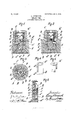
- FIG. l is an axial longitudinal section of the secured fuse of one embodiment of the invention and part of the base of the shot.
- Fig. 2 is a view corresponding to Fig. 1, the securing device being withdrawn.
- Fig. 3 is a section on line 3 3 of Fig. 1 seen from above.
- Figs. 4 and 5 are detail views, and Fig. 6 shows a part oi a second embodiment of the invention in a view corresponding to Fig.v 1.
- the sleeve D fits by the Aneedle-carrier C.
- the sleeve D has two perforations d,.located diamet-l rically opposite each otlierfand the cylinvdrie wall of the primer-bolt E is provided with an annular groove e of rectangular cross-section.
- the diameter of the perfo-- rations d corresponds to the width of the .groove e', (measured in the direction of the .ongitudinal axis of the fuse.)
- the location rom rebounding from 'the strips of the groove e is such that the groove registers with the perforations d when the primerbolt E is in the position of transport.
- each of the perforations cl registers with a perforation bin .the fusebody.
- The' perforations b are c oaxial with the perforations d and are preferably of slightly greater diameter than the perforations d.
- each of the balls F is retained in the securing position by the free end of a-sheet-metal strip Gr (See valso Fig. 5.)
- the strips G are integral with a ring G which is jammedbetween the sleeve D and theneedle-carrier C.
- the thickness of the wall of the sleeve D is such that when the balls are in the i securing position they lie against thebottom of the groove e and the strips G and the strips assame the straight position shown in Figs. 1 and 5.
- the strips are of such elastic material and such dimensions that when the balls move outwardly under the action ofthe centrifugal force the strips can be bent by the balls to such an extent.that the balls can reach the position shown in Fig. 2 and that the strips after they balls rebound to assume a lposition such'as that shown in Fig. 2.
- Figs- 1 and 2 The free ends of the strips are. therefore a sort of s ring-naps, which can swing on an axis whic is located m the roximity of the upper edge of the recesses
- Theoperation of the securing device is as follows: When the gun is discharged, the cetriiu al force causes the balls F to move outwardly to the position shown in Fig. 2. The primer-bolt E is thus released and the fuse is ready for ignition. During their outward movement the balls F bend the ends of the sheet-metal stri s G so far outwardly until the balls allow the elasticity of the strips to return the strips to the position shown in Fig. 2.
- the ,sheet-metal strips prevent the balls F from returning to the securing position under the action of lateral shocks to secure the primerbolt E against forward movement. Such shocks may be caused by the shot hitting the target sidewise.
- the sheet-metal strips G thus form both a transport-securing means for the balls and a means for preventing blind shots.
- the ring G and the strips G are replaced by a flap H, which is hinged to the sleeve D in the prox-g ⁇ imity of the upper edge. of the recesses b2 and which is under the action of a spring 71', that is secured to the fuse-body B.
- the mode of operation of this embodiment is similar to that of the embodiment shown in Figs. 1 to 5 with relation to the securing of the balls in the position of transport, Fig. 6, and in the withdrawn position.
Landscapes
- Engineering & Computer Science (AREA)
- General Engineering & Computer Science (AREA)
- Fuses (AREA)
Description
No. 809,885. l-ATBNTED JAN. 9, 1906.
' L. ABENDROTH.
IMPACT FUSE.
APPLICATION FILED Muze, 1995.
D69# F l I a .5.a F
\\\ vAW 2 n0. d a a F DU nn. HFfef nzd g ...0 FFA M i. 4%- l l f Je Ea\\ \\.F F\\\ af 3. @k H la /A .L m
UN rTED STATES PATENT oEE-roE.
' Louis ABENDRoTH, or ETTENsoHEm,
NEAR EssEaoN-THE-RUHE,
GERMANY. AssreNoR To EETED. KEUPP AKTIENGESELLSCHAFT, or EssEN-oN-THEEUHE., GERMANY., A
l Immo-fumes.
l N0. 809,885. l
Patented J an. 9, 1906.
Application iiled May 26, 1905. Serial No. 262,455.
:all whom t may concern.-
-Be it known that I, LOUIS ABENDROTH, a subject of the German Emperor, and a resi-v dent of Andreasstrasse,4 lRi'ittenscheid,
near Essen-on-the-R'uhr, Germany, have Jn` vented certain new and useful Improvements in ImpactFuses, of which the following isa specification. I The present inventionrelates to impactfuses provided with a securing device, whichis withdrawn by the centrifugal force during the rotation of theshot; and the object of the invention is to prevent the return. of the withdrawn securing device when t ye shot hits the target. The means which I employ for the said purpose are of simple construc- I' tion and reliably hold the securing devicein the withdrawn osition, thereby excluding the possibility'o blind shots.
Two embodiments i of the invention are shown as applied to a basefuse in the accompanying drawings, in which- Figure l is an axial longitudinal section of the secured fuse of one embodiment of the invention and part of the base of the shot. Fig. 2 is a view corresponding to Fig. 1, the securing device being withdrawn. Fig. 3 is a section on line 3 3 of Fig. 1 seen from above.
Figs. 4 and 5 are detail views, and Fig. 6 shows a part oi a second embodiment of the invention in a view corresponding to Fig.v 1.
- the fuse-body. The
The fuse-body B, Figs. 1 to 3 and Fig; 6, which is screwed into the base A of the shot, provided with a central bore receiving a cylindric sleeve D (see also Fig. 4) and closed The sleeve D fits by the Aneedle-carrier C.
tightly within the fuse-body B and cannot move in the direction of the axis, and it is held from rotation within the fuse-body by means of a. stud d2, which projects into a recess in cylindric primer-bolt E is slidably arranged in the sleeve D. In order to secure the primer-bolt in the position of transport shown in the drawings, the following arrangement is provided: The sleeve D has two perforations d,.located diamet-l rically opposite each otlierfand the cylinvdrie wall of the primer-bolt E is provided with an annular groove e of rectangular cross-section.
The diameter of the perfo-- rations d corresponds to the width of the .groove e', (measured in the direction of the .ongitudinal axis of the fuse.) The location rom rebounding from 'the strips of the groove e is such that the groove registers with the perforations d when the primerbolt E is in the position of transport. When the fuse is in the secured position, Figs. 1, 3, and 6, each oi the perforations cl', withthe adjacent parts of the annular groove e', receives a ball F, which is of same diameter as the periorations, while the depth of the groove e is equal to the radius of the balls. The balls F, which rest on the bottom of the groove e', prevent the primerebolt'E from moving toward the needle during the transport of the fuse and also prevent the bolt tom oi' the fuse-body B) under the reaction of the shock caused by the firing. The balls F constitute the moving part of the securing device to be withdrawn by 'the centrifugal torce. In orderl to provide for. the withdrawing of the balls, each of the perforations cl registers with a perforation bin .the fusebody. The' perforations b are c oaxial with the perforations d and are preferably of slightly greater diameter than the perforations d. Furthermore, the wall of the bore of the base A, which receives the fuse, is provided with an annular groove a. In the embodiment shown in Figs. l to 5 each of the balls F is retained in the securing position by the free end of a-sheet-metal strip Gr (See valso Fig. 5.) The strips G are integral with a ring G which is jammedbetween the sleeve D and theneedle-carrier C. The
portion of the strips that is located between the perforation d and the ring Grests in a groove d3, Fig. 4', in the which corresponds Vto the thickness of the strips Gr. The thickness of the wall of the sleeve D is such that when the balls are in the i securing position they lie against thebottom of the groove e and the strips G and the strips assame the straight position shown in Figs. 1 and 5. The strips are of such elastic material and such dimensions that when the balls move outwardly under the action ofthe centrifugal force the strips can be bent by the balls to such an extent.that the balls can reach the position shown in Fig. 2 and that the strips after they balls rebound to assume a lposition such'as that shown in Fig. 2. In order to ermit of G being bent by its support (the bot! sleeve, the depth of have been bent by the the bals F, re-
IOC
cesses bzare provided in the fuse-bodyB, as
shown in Figs- 1 and 2. The free ends of the strips are. therefore a sort of s ring-naps, which can swing on an axis whic is located m the roximity of the upper edge of the recesses Theoperation of the securing device is as follows: When the gun is discharged, the cetriiu al force causes the balls F to move outwardly to the position shown in Fig. 2. The primer-bolt E is thus released and the fuse is ready for ignition. During their outward movement the balls F bend the ends of the sheet-metal stri s G so far outwardly until the balls allow the elasticity of the strips to return the strips to the position shown in Fig. 2. Inv this position the ,sheet-metal strips prevent the balls F from returning to the securing position under the action of lateral shocks to secure the primerbolt E against forward movement. Such shocks may be caused by the shot hitting the target sidewise. The sheet-metal strips G thus form both a transport-securing means for the balls and a means for preventing blind shots. A
In the embodiment shown in Fig. 6 the ring G and the strips G are replaced by a flap H, which is hinged to the sleeve D in the prox-g` imity of the upper edge. of the recesses b2 and which is under the action of a spring 71', that is secured to the fuse-body B. The mode of operation of this embodiment is similar to that of the embodiment shown in Figs. 1 to 5 with relation to the securing of the balls in the position of transport, Fig. 6, and in the withdrawn position.
Without departing from the scope of my invention Imight substitute a short bolt having round ends For the balls F.
Having described my invention, what I claim as new is- 1. In an im act-fuse, the combination with a longitudina y-movable primer-bolt, of cen,- trifugally-operated securing means movable transversely of the bolt to release said bolt, and means projecting into the path of travel of said securingmeans and constructed to be moved out of the path of said securing means, when said securing means is moved by c entrifugal force, to Ipermit the securing'means to unlock the primer-bolt, and to move again into the path of the securing means to prevent the said securing means again locking the primer-bolt.
2. The combination Withthe centrifugallyoperated securing means of a fuse, of means moved by the securing means during its outward travel and adapted to enter the path of travel of the securing means after the passage of said securing means to prevent the return thereof.
3. The combination with the centrifugallyoperated securing device of a fuse, ofmeansprojecting into the path of travel of the mov able part of said'securing device and holding said part in the secured position said means being adapted to be displaced by the movable part of the securing device lto permit the outward movement thereof and rebounding to secure said part in its outer position.
The foregoing specification signed at Dsseldoxf this 13th day of May, 1905.
LOUIS ABENDROTH.A
In presence of- PETER LIEBER, E. HERBER.
Priority Applications (1)
| Application Number | Priority Date | Filing Date | Title |
|---|---|---|---|
| US26245505A US809885A (en) | 1905-05-26 | 1905-05-26 | Impact-fuse. |
Applications Claiming Priority (1)
| Application Number | Priority Date | Filing Date | Title |
|---|---|---|---|
| US26245505A US809885A (en) | 1905-05-26 | 1905-05-26 | Impact-fuse. |
Publications (1)
| Publication Number | Publication Date |
|---|---|
| US809885A true US809885A (en) | 1906-01-09 |
Family
ID=2878366
Family Applications (1)
| Application Number | Title | Priority Date | Filing Date |
|---|---|---|---|
| US26245505A Expired - Lifetime US809885A (en) | 1905-05-26 | 1905-05-26 | Impact-fuse. |
Country Status (1)
| Country | Link |
|---|---|
| US (1) | US809885A (en) |
Cited By (1)
| Publication number | Priority date | Publication date | Assignee | Title |
|---|---|---|---|---|
| US2966856A (en) * | 1946-02-07 | 1961-01-03 | Howard E Tatel | Magnetic detonator |
-
1905
- 1905-05-26 US US26245505A patent/US809885A/en not_active Expired - Lifetime
Cited By (1)
| Publication number | Priority date | Publication date | Assignee | Title |
|---|---|---|---|---|
| US2966856A (en) * | 1946-02-07 | 1961-01-03 | Howard E Tatel | Magnetic detonator |
Similar Documents
| Publication | Publication Date | Title |
|---|---|---|
| KR870000572A (en) | Self-destructive fuses for secondary bullets fired from rockets | |
| US809885A (en) | Impact-fuse. | |
| US3410214A (en) | Percussion fuze | |
| US1043074A (en) | Trajectory regulator for projectiles. | |
| US813641A (en) | Automatic prick-punch. | |
| US720775A (en) | Firearm. | |
| US2362987A (en) | Fuse | |
| US1369401A (en) | Magazine-pistol | |
| US511069A (en) | Terlinus | |
| US752893A (en) | evensen | |
| US535174A (en) | Powder-charger for blast-holes | |
| US785846A (en) | Impact-fuse. | |
| US7572A (en) | Improvement in gun harpoons and lances | |
| US988846A (en) | Impact-fuse. | |
| US35611A (en) | Improvement in concussion-fuse for explosive shells | |
| US1319693A (en) | Toy pistol and projectile | |
| US410434A (en) | Toy gun | |
| US480142A (en) | Projectile | |
| US533101A (en) | Breech mechanism for ordnance | |
| US763229A (en) | Shell-fuse. | |
| US859610A (en) | Centrifugal percussive fuse for projectiles. | |
| US505568A (en) | Breech-block | |
| US1958A (en) | Improvement in the manner of discharging fire-arms of various kinds | |
| US1333777A (en) | Fuse | |
| US1105848A (en) | Projectile |