US80930A - durfee - Google Patents
durfee Download PDFInfo
- Publication number
- US80930A US80930A US80930DA US80930A US 80930 A US80930 A US 80930A US 80930D A US80930D A US 80930DA US 80930 A US80930 A US 80930A
- Authority
- US
- United States
- Prior art keywords
- crane
- shaft
- chains
- pulleys
- pulley
- Prior art date
- Legal status (The legal status is an assumption and is not a legal conclusion. Google has not performed a legal analysis and makes no representation as to the accuracy of the status listed.)
- Expired - Lifetime
Links
- 230000003028 elevating effect Effects 0.000 description 2
- 101100016398 Danio rerio hars gene Proteins 0.000 description 1
- 238000009432 framing Methods 0.000 description 1
Images
Classifications
-
- B—PERFORMING OPERATIONS; TRANSPORTING
- B66—HOISTING; LIFTING; HAULING
- B66C—CRANES; LOAD-ENGAGING ELEMENTS OR DEVICES FOR CRANES, CAPSTANS, WINCHES, OR TACKLES
- B66C23/00—Cranes comprising essentially a beam, boom, or triangular structure acting as a cantilever and mounted for translatory of swinging movements in vertical or horizontal planes or a combination of such movements, e.g. jib-cranes, derricks, tower cranes
- B66C23/18—Cranes comprising essentially a beam, boom, or triangular structure acting as a cantilever and mounted for translatory of swinging movements in vertical or horizontal planes or a combination of such movements, e.g. jib-cranes, derricks, tower cranes specially adapted for use in particular purposes
- B66C23/20—Cranes comprising essentially a beam, boom, or triangular structure acting as a cantilever and mounted for translatory of swinging movements in vertical or horizontal planes or a combination of such movements, e.g. jib-cranes, derricks, tower cranes specially adapted for use in particular purposes with supporting couples provided by walls of buildings or like structures
Definitions
- This invention relates to al new and improved crane, designed more especially'to be operated by steam or horse-power, and for raising'and lowering heavy bodies.
- the object ot' theinvention is to obtain a crane of the kind specified,'whieh may be operated or manipu lated with 'the greatest facility, be simplein construction, not liable ⁇ to get out of repair, and which may be constructed at an underrate cost.
- the frame of the crane is composed'of two uprights, a a, two horizontal' bars, b Z1, and two diagonal brace- -v bars, c e, all framed together, and4 secured irxnly by properiron-work at their connections.
- the form or shape of the crane is shown clearly in'g. 1.
- the lower end ofthe crane is fitted in a proper step, d, and the upper'end is fitted on a head-piece, e, the crane being allowed to turn freely, and the step andihead-piece attached toa suitahleframing, A.
- thiscross-'bar there areiitted loosely two pulleys, D D, aroundwhichchains E E pass.
- These chains are attachedat ⁇ one end to a cross-bar, g, at the outer ends of the horizontalbars'lffb of the crane, and the opposite ends of said chains are attached to a lever, F, which is secured-in a cap, G, on the upper ends of the uprights a a, the chains also passing over suitable guide-pulleys, a, near the rear of. the bars bb.
- VH is acarriage, which runs on ways on the horizontal hars b b, and has two pairs ⁇ of pendent pulleys, I, attached, over which the chains E E pass, and on the loop ot'. thc'ehains, between the pulleys I, two pulleys, d', are fitted, which are in a frame, having a hook, K, attached, ('see iig. 1.) The article to be raised or lowered is suspended toI this hook.
- This shaft has a sp'irally-groovcd. pulley, M, upon it, and a worm-wheel, N, at one end,lsai'd worm-wheel-N gearing into a screw, ⁇ O, having a pulley, P, on Aits outer end.
- ⁇ Q is a rope or chain, which passes around the pulley M on'shaft L, with severaltconvolutions, and also passes around a pulley, R, at the outer side ot' thecross-bar gf This rope or chain is attached to the front 'and rear ends of ⁇ the carriage H, as shown clearly in lig. 1.
- pulleys V V havel belts Y Y passing over them fronn a driving-shaft, Z; Y being a straight belt,l and passing over pulley V, and Y a cross-belt, and passing over ⁇ pulley V', (see iig. 2:)
- v 4On the lower part of thc screw B'therc is keyed a bevel-wheel, 7L, into which a bevel-pinion, z', on a horizontal shaft, A', gears, said shaft having aband-wheel, B', on itsV outer end.
- the article suspended to hook K may he raised and lowered by the. revolution of the screw B, the latter being turned in either direction by engaging the clutchW with pulley V or V.
- the latter In elevating' or lowering the article on hook K of the carriageH, the latter is at thc outer part of the bars b b, andvin elevating articles, when the latter are fully raised, the carriage, when necessary, may be drawn inward on the bars b b by turning the shaft L, and the elevated article lowered;
- the crane By turning the shaft A', the cranemay be moved to the right or left with the greatest facility.
- This crane may be operated with the greatest facility, it is very compact, may be worked by steam or horse-power, and constructed at a reasonable cost.
Landscapes
- Engineering & Computer Science (AREA)
- Civil Engineering (AREA)
- Structural Engineering (AREA)
- Mechanical Engineering (AREA)
- Jib Cranes (AREA)
Description
W. F. DURFEE, e OF' NEW BEDFORD, MASSACHUSETTS Lam Patent No. 80,930, daad anymail, '1868.
'iMPRovsMBNr 1N POWER-casus.'
@la tlgehule referat la 'in tipa-Estate @that mit 'nuttig gaat ut tige smite,
To ALL WHOM rr MAYeoNenn-N; Y
Be it known that I,"W. F. DURFEE, of New Bedford, in 'the county of Bristol,v and State of Massachusetts,- have invented a new andi-improved Power-Crane; andrI do hereby declare that the following is a'iull, clear, and exact description' thereof, whiehnwill enable others skilled in the art to make and use the same, reference being had to the accompanying drawin'gaforming part of this specification. v
This invention relates to al new and improved crane, designed more especially'to be operated by steam or horse-power, and for raising'and lowering heavy bodies.
The object ot' theinvention is to obtain a crane of the kind specified,'whieh may be operated or manipu lated with 'the greatest facility, be simplein construction, not liable` to get out of repair, and which may be constructed at an underrate cost. A
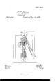
In the accompanying sheet of d'rawingsl `Figure 1,.Sheet No. 1, is aside sectional view of my invention, taken in the line x x, iig'. 2.
Figure'2, lSheet No. 2, a'vertical section of thesame, taken in the line`y y, hg. 1.
`Similar.Iette'rsof reference indicate corresponding parts.l
The frame of the crane is composed'of two uprights, a a, two horizontal' bars, b Z1, and two diagonal brace- -v bars, c e, all framed together, and4 secured irxnly by properiron-work at their connections. The form or shape of the crane is shown clearly in'g. 1.
The lower end ofthe crane is fitted in a proper step, d, and the upper'end is fitted on a head-piece, e, the crane being allowed to turn freely, and the step andihead-piece attached toa suitahleframing, A.
B is ascrew, which is tted vertically in the framing A, and passes down between the uprights a a of the crane. 4This screw passes through a nut, e, ina cross-har, G, which is allowed to rise and `fall freely between the uprights a a, the ends of said cross-bar being fitted in guidesf, at the inner sides ot'said uprights.
0n thiscross-'bar there areiitted loosely two pulleys, D D, aroundwhichchains E E pass. These chains are attachedat` one end to a cross-bar, g, at the outer ends of the horizontalbars'lffb of the crane, and the opposite ends of said chains are attached to a lever, F, which is secured-in a cap, G, on the upper ends of the uprights a a, the chains also passing over suitable guide-pulleys, a, near the rear of. the bars bb.
VH is acarriage, which runs on ways on the horizontal hars b b, and has two pairs` of pendent pulleys, I, attached, over which the chains E E pass, and on the loop ot'. thc'ehains, between the pulleys I, two pulleys, d', are fitted, which are in a frame, having a hook, K, attached, ('see iig. 1.) The article to be raised or lowered is suspended toI this hook. y l i i v v v Lis a shaft, which -pas'ses horizontally through the barsb bei' the crane, near thfuprights a ca This shaft has a sp'irally-groovcd. pulley, M, upon it, and a worm-wheel, N, at one end,lsai'd worm-wheel-N gearing into a screw, `O, having a pulley, P, on Aits outer end.
` Q is a rope or chain, which passes around the pulley M on'shaft L, with severaltconvolutions, and also passes around a pulley, R, at the outer side ot' thecross-bar gf This rope or chain is attached to the front 'and rear ends of` the carriage H, as shown clearly in lig. 1. v
0n Vthe upper part ofthe screw B there is keyed a bevel-wheel, S, into which a bevel-pinion, T, on a. horizontal shaft, U, gears, the latter having two loose-pulleys, V V', placed on it, with either of which a clutch may hemade to engage by adjusting a band=lever, X.
These pulleys V V havel belts Y Y passing over them fronn a driving-shaft, Z; Y being a straight belt,l and passing over pulley V, and Y a cross-belt, and passing over `pulley V', (see iig. 2:)
v 4On the lower part of thc screw B'therc is keyed a bevel-wheel, 7L, into which a bevel-pinion, z', on a horizontal shaft, A', gears, said shaft having aband-wheel, B', on itsV outer end.
It will be seen, from the above description, that the article suspended to hook K may he raised and lowered by the. revolution of the screw B, the latter being turned in either direction by engaging the clutchW with pulley V or V. In elevating' or lowering the article on hook K of the carriageH, the latter is at thc outer part of the bars b b, andvin elevating articles, when the latter are fully raised, the carriage, when necessary, may be drawn inward on the bars b b by turning the shaft L, and the elevated article lowered;
By turning the shaft A', the cranemay be moved to the right or left with the greatest facility. v
j In consequence of'havi'ng one end of the chains E E attached to the lever F, any difference in the tension of the `two chains will he compensated for. v
This crane may be operated with the greatest facility, it is very compact, may be worked by steam or horse-power, and constructed at a reasonable cost.
I claim asnew, and desire to secure'by Letters Patent- T 1. The screw B, with the nut eand pulleys D D attached, in connection with the chains E E and carriage H, all arranged and applied to the crane, to operate in the manner substantially as` and for the purpose set forth.. 2, The lever Fin combination with the chains E E, for the purpose of compensating for any inequality of. tension between the two chains, as herein set forth and shown.
3. The spirally-grooved pulley M on the shaft L, rope or chain Q, andthe shaft L, operated by the screii gear, all 'arranged for moving the earriage'H on the bars 6 b, substantially as set forth.
4. The bevel-wheelh on the screw B, and pinion e on shaft A', arranged substantially as shown and described, lfor turning or adjusting the crane.
W; F. DURFEE. Witnesses Gao. A. Bourne, CHAs. H. BoUnNn.
Publications (1)
| Publication Number | Publication Date |
|---|---|
| US80930A true US80930A (en) | 1868-08-11 |
Family
ID=2150425
Family Applications (1)
| Application Number | Title | Priority Date | Filing Date |
|---|---|---|---|
| US80930D Expired - Lifetime US80930A (en) | durfee |
Country Status (1)
| Country | Link |
|---|---|
| US (1) | US80930A (en) |
Cited By (1)
| Publication number | Priority date | Publication date | Assignee | Title |
|---|---|---|---|---|
| CN110775835A (en) * | 2019-11-08 | 2020-02-11 | 北京特种机械研究所 | Rotatable manual hoisting mechanism for shelter |
-
0
- US US80930D patent/US80930A/en not_active Expired - Lifetime
Cited By (1)
| Publication number | Priority date | Publication date | Assignee | Title |
|---|---|---|---|---|
| CN110775835A (en) * | 2019-11-08 | 2020-02-11 | 北京特种机械研究所 | Rotatable manual hoisting mechanism for shelter |
Similar Documents
| Publication | Publication Date | Title |
|---|---|---|
| US80930A (en) | durfee | |
| US96718A (en) | Improved belt-tightener | |
| US71990A (en) | Improvement in machine foe steetohiig cloth | |
| US47773A (en) | Chakles k | |
| US99913A (en) | Improvement in machine for smoothing spokes | |
| US78646A (en) | Improvement in eieyatoes | |
| US61835A (en) | Jambs ingram | |
| US105359A (en) | Improved stone-sawing machine | |
| US70412A (en) | Hentet chatfibld | |
| US83970A (en) | Improvement in hand-spinning machine | |
| US92531A (en) | Improvement in door-clamp | |
| US41779A (en) | Improvement in hoisting-machines | |
| US80164A (en) | Michael g | |
| US43234A (en) | Improvement in windlasses | |
| US83362A (en) | Improvement in jio-saws | |
| US101745A (en) | Improvement in belt-shifters | |
| US327588A (en) | Planing-machine | |
| US319603A (en) | Half to mer win mckaig | |
| US66722A (en) | lyman | |
| US74173A (en) | tuttle | |
| US68001A (en) | Potter | |
| US126093A (en) | Improvement in swinging saws | |
| US84577A (en) | Improvement in apparatus for raising weights | |
| US78093A (en) | Improvement in machines foe polishing wood | |
| US79503A (en) | James see |