US809243A - Mop-holder. - Google Patents
Mop-holder. Download PDFInfo
- Publication number
- US809243A US809243A US19919204A US1904199192A US809243A US 809243 A US809243 A US 809243A US 19919204 A US19919204 A US 19919204A US 1904199192 A US1904199192 A US 1904199192A US 809243 A US809243 A US 809243A
- Authority
- US
- United States
- Prior art keywords
- stick
- spring
- lever
- bail
- shaped bends
- Prior art date
- Legal status (The legal status is an assumption and is not a legal conclusion. Google has not performed a legal analysis and makes no representation as to the accuracy of the status listed.)
- Expired - Lifetime
Links
- 238000010276 construction Methods 0.000 description 1
- 229920000136 polysorbate Polymers 0.000 description 1
Images
Classifications
-
- A—HUMAN NECESSITIES
- A47—FURNITURE; DOMESTIC ARTICLES OR APPLIANCES; COFFEE MILLS; SPICE MILLS; SUCTION CLEANERS IN GENERAL
- A47L—DOMESTIC WASHING OR CLEANING; SUCTION CLEANERS IN GENERAL
- A47L13/00—Implements for cleaning floors, carpets, furniture, walls, or wall coverings
- A47L13/10—Scrubbing; Scouring; Cleaning; Polishing
- A47L13/42—Details
- A47L13/46—Securing scouring or polishing cloths or sponges to the handles by gripping means, tongs, or the like
Definitions
- HARRY BITNER OF BERWYN, ILLINOIS, ASSIGNOR TO ARCADE MANU- FAOTURING COMPANY, OF FREEPORT, ILLINOIS, A CORPORATION OF ILLINOIS.
- My invention relates to improvements in mop-holders, the purpose of which is to put certain parts thereof into simple and convenient form and to cheapen the cost, at the same time improving so far as possible the general makeup of the device.
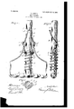
- Figure 1 is a front view of. the lower portion of the mop-holder, including all of the working parts thereof.
- Fig. 2 is a side view of the same, and
- Fig. 3 is a horizontal section in the line 3 3 of Fig. 1 looking downward.
- a stick A, a cross-head B, secured thereon at the lower end, and a bail O, guided on the crosshead and extending therefrom along the stick, are preferably arranged as is customary in similar devices.
- a spring D is placed upon the stick above the crosshead, and one of the upper coils thereof, d, has oppositely-extending U shaped bends d (1 which afford a simple, convenient, and effective means by which an opening and closing lever E may be pivoted at its lower end to the spring by means of eyes 6 e, encircling, respectively, one of the sides of the U-shaped bends in the spring.
- the portion of the wire of the spring adjacent to the U shaped bend d which is farther up the coil of the spring than the bend d is preferably brought downward to ward the next lower coil, as at (i to furnish a bearing against said coil, avoiding any ossibility of an unequal thrust of the end 0 the lever upon the two sides of the spring.
- the lever E is preferably formed of wire bent at its middle portion 6 to form the upper end of the lever, the two parts of the wire being brought down and pivoted to the spring by means of the eyes aboye referred to. Be-
- my improved device follows similar devices of the same class, the opening and closing of the aws of the mop being effected by the swinging of the lever upon its pivotal connection with the spring and its pivotal connection with the bail passing through the plane of the cross-head and the springpivots, so as to lock the lever when closed.
- the spring is adapted to yield to such an extent as is desirable to permit of the movements of the lever and to accommodate the mop holder to various thicknesses of cloths.
Landscapes
- Cleaning Implements For Floors, Carpets, Furniture, Walls, And The Like (AREA)
Description
PATENTED JAN. 2-, 1906.
H. BITNER.
P HOLDER.
IUAT
UNITED STATES PATENT OFFICE.
HARRY BITNER, OF BERWYN, ILLINOIS, ASSIGNOR TO ARCADE MANU- FAOTURING COMPANY, OF FREEPORT, ILLINOIS, A CORPORATION OF ILLINOIS.
MOP-HOLDER.
Specification of Letters Patent.
Patented. 'J' an. 2, 1906.
To all whom it may concern.-
Be it known that I, HARRY BITNER, a citizen of the United States of America, residing at Berwyn, in the county of Cook and State of Illinois, have invented certain new and useful Improvements in MopI-Iolders, of which the following is a specification.
' My invention relates to improvements in mop-holders, the purpose of which is to put certain parts thereof into simple and convenient form and to cheapen the cost, at the same time improving so far as possible the general makeup of the device.
To these ends it consists in certain novel features or characteristics of the various parts, which will be. fully described in connection with the preferred construction and the essential portions thereof be clearly pointed out in the claims appended hereto.
In the drawings, Figure 1 is a front view of. the lower portion of the mop-holder, including all of the working parts thereof. Fig. 2 is a side view of the same, and Fig. 3 is a horizontal section in the line 3 3 of Fig. 1 looking downward.
In the preferred form of my device a stick A, a cross-head B, secured thereon at the lower end, and a bail O, guided on the crosshead and extending therefrom along the stick, are preferably arranged as is customary in similar devices. A spring D is placed upon the stick above the crosshead, and one of the upper coils thereof, d, has oppositely-extending U shaped bends d (1 which afford a simple, convenient, and effective means by which an opening and closing lever E may be pivoted at its lower end to the spring by means of eyes 6 e, encircling, respectively, one of the sides of the U-shaped bends in the spring. The portion of the wire of the spring adjacent to the U shaped bend d which is farther up the coil of the spring than the bend d is preferably brought downward to ward the next lower coil, as at (i to furnish a bearing against said coil, avoiding any ossibility of an unequal thrust of the end 0 the lever upon the two sides of the spring. The lever E is preferably formed of wire bent at its middle portion 6 to form the upper end of the lever, the two parts of the wire being brought down and pivoted to the spring by means of the eyes aboye referred to. Be-
tween the upper and lower ends of the lever the latter has opposite outwardly-extending U-shaped bends e e, upon one of the sides of which the upper ends of the bail O are respectively pivoted by means of eyes 0 0. These opposite outwardly or laterally extending U- shaped bends of the lever furnish an exceedingly simple, cheap, and convenient means of pivoting the upper ends of the bail there-- to. They are easy to make, afford an excellent pivotal connection, and do not interfere with making the lever in a neat and attractive form.
In operation my improved device follows similar devices of the same class, the opening and closing of the aws of the mop being effected by the swinging of the lever upon its pivotal connection with the spring and its pivotal connection with the bail passing through the plane of the cross-head and the springpivots, so as to lock the lever when closed. The spring is adapted to yield to such an extent as is desirable to permit of the movements of the lever and to accommodate the mop holder to various thicknesses of cloths.
I claim as new and desire to secure by Letters Patent 1. The combination with a stick, a crosshead on the end of the stick, and a bail guided on the cross-head and extending therefrom along the stick, of a spring on the stick above the cross-head, one of the upper coils of said spring being provided with oppositely-extending U-shaped bends, and a lever pivoted upon said U-shapedbends and connected with the upper ends of the bail.
2. The combination with a stick, a crosshead on the lower end thereof, and a bail guided on the cross-head and extending therefrom along the stick, of a lever pivotally supported at its lower end adjacent to the stick, said lever being formed of wire having oppositely-extending U-shaped bends and suitable connections with the bail pivoted I upon said U-shaped bends.
3. The combination with a stick, a crosshead on the lower end thereof, and a bail guided on the cross-head and extending therefrom along the stick, of a lever pivotally supported at its lower end adjacent to the stick, said lever being formed of wire having oppositely-extending U-shaped bends and eyes upon the upper ends of the bail, pivoted upon said U-shaped bends.
4. The combination with a stick, a crosshead on the end of the stick and a bail guided on the cr0ss-head and extending therefrom along the stick, of a spring on the stick above the cross-head, a lever bent into approximately U shape, having a bearing at its lower end upon the upper portion of the spring, and having laterally-extending U-shaped bends by means of which it is pivoted to the upper ends of the bail.
5. The combination with a stick, a crosshead on the end of the stick, and a bail guided on the crosshead and extending therefrom along the stick, of a spring on the stick above the cross-head, one'of the upper coils of said spring having laterally-extending U- shaped bends and the wire adjacent to the upper bend brought down toward the next coil of the spring to afl'ord a bearing thereon, and alever pivoted upon said U-shaped bends and connected to the upper end of the bail.
6. The combination with a stick, a crosshead on the end of the stick, and a bail guided on the cross-head and extending therefrom along the stick, of a spring on the stick above the cross-head, one of the upper coils of said spring being formed with oppositelyextending U-shaped bends, and an approximately U-shaped wire lever pivoted by means of the ends of the. wire upon the U- shaped bends, and having, between its ends, laterallyextending U-shaped bends upon which the upper ends of the bail are pivoted.
In witness whereof I have signed the above application for Letters Patent, at Chicago, in the county of Cook and State of Illinois, this 1st day of March, 1904.
HARRY BITNER.
Witnesses:
CHAS. O. SHERVEY, RUssELL WILES.
Priority Applications (1)
| Application Number | Priority Date | Filing Date | Title |
|---|---|---|---|
| US19919204A US809243A (en) | 1904-03-21 | 1904-03-21 | Mop-holder. |
Applications Claiming Priority (1)
| Application Number | Priority Date | Filing Date | Title |
|---|---|---|---|
| US19919204A US809243A (en) | 1904-03-21 | 1904-03-21 | Mop-holder. |
Publications (1)
| Publication Number | Publication Date |
|---|---|
| US809243A true US809243A (en) | 1906-01-02 |
Family
ID=2877724
Family Applications (1)
| Application Number | Title | Priority Date | Filing Date |
|---|---|---|---|
| US19919204A Expired - Lifetime US809243A (en) | 1904-03-21 | 1904-03-21 | Mop-holder. |
Country Status (1)
| Country | Link |
|---|---|
| US (1) | US809243A (en) |
-
1904
- 1904-03-21 US US19919204A patent/US809243A/en not_active Expired - Lifetime
Similar Documents
| Publication | Publication Date | Title |
|---|---|---|
| US899084A (en) | Box-fastener. | |
| US809243A (en) | Mop-holder. | |
| EP1764557A2 (en) | Compact hinge device for a door | |
| US910648A (en) | Handle. | |
| US57149A (en) | Improvement in lamp-chimney cleaners | |
| US361852A (en) | File-case | |
| US322151A (en) | beaumont | |
| US504887A (en) | Broom or brush holder | |
| US685858A (en) | Mop-head. | |
| US1240427A (en) | Cooking utensil. | |
| US833291A (en) | Mop-head. | |
| US749940A (en) | A corpo | |
| US654501A (en) | Attachment for carriage-boots. | |
| US2116799A (en) | Barrette | |
| US952303A (en) | Line-chalking device. | |
| US984793A (en) | Equalizer. | |
| US948171A (en) | Sash-weight. | |
| US1003842A (en) | Clothes-pin. | |
| US550449A (en) | Mop head | |
| US943920A (en) | Adjustable chairs. | |
| US1004613A (en) | Brush-holder. | |
| US964117A (en) | Document-file. | |
| US1651853A (en) | Mop holder | |
| US1196465A (en) | Mop. | |
| US733555A (en) | Mop-head. |