US809051A - Invalid-bed. - Google Patents
Invalid-bed. Download PDFInfo
- Publication number
- US809051A US809051A US26154705A US1905261547A US809051A US 809051 A US809051 A US 809051A US 26154705 A US26154705 A US 26154705A US 1905261547 A US1905261547 A US 1905261547A US 809051 A US809051 A US 809051A
- Authority
- US
- United States
- Prior art keywords
- bed
- plate
- link
- pan
- mattress
- Prior art date
- Legal status (The legal status is an assumption and is not a legal conclusion. Google has not performed a legal analysis and makes no representation as to the accuracy of the status listed.)
- Expired - Lifetime
Links
- 239000004744 fabric Substances 0.000 description 2
- 210000000707 wrist Anatomy 0.000 description 2
- 238000010276 construction Methods 0.000 description 1
- 210000004247 hand Anatomy 0.000 description 1
- 239000002184 metal Substances 0.000 description 1
- 230000000284 resting effect Effects 0.000 description 1
- 230000000717 retained effect Effects 0.000 description 1
- 239000011435 rock Substances 0.000 description 1
Images

Classifications
-
- A—HUMAN NECESSITIES
- A61—MEDICAL OR VETERINARY SCIENCE; HYGIENE
- A61G—TRANSPORT, PERSONAL CONVEYANCES, OR ACCOMMODATION SPECIALLY ADAPTED FOR PATIENTS OR DISABLED PERSONS; OPERATING TABLES OR CHAIRS; CHAIRS FOR DENTISTRY; FUNERAL DEVICES
- A61G7/00—Beds specially adapted for nursing; Devices for lifting patients or disabled persons
- A61G7/02—Beds specially adapted for nursing; Devices for lifting patients or disabled persons with toilet conveniences, or specially adapted for use with toilets
Definitions
- This invention relates to improvements inV beds for invalids or bedridden persons, designed vto facilitate attendance upon such persons.
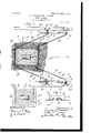
- Figure 1 is a side elevation of a bed structure embodying our improvements.
- Fig. 2 is a detail plan view of the structure with mattress removed and 'frame broken away, showing the devices for operating the bed-pan and pad.
- Fig. 3 is a 'section at the line 3 3 on Fig. 2, showing the mattress and pad in position.
- Fig. 4 is a detail section at the line 4 4 on Fig. 1.
- Fig. 5 is a longitudinal vertical section of the bed- Fig. 6 is a bottom plan view of the same.
- Fig. 7 is a detail section through the bottom portion of the bed-pan and the plate on which it is carried, showing the means of securing the parts together.
- Fig. 8 is a plan view of the pan-supporting plate.
- Fig. 9 is a longitudinal section of the pan and carrying-plate in a modified form.
- Fig. 1() is a transverse section of the same at the line 10 V10 on Fig. 9.
- the mattress 1 which rests upon a suitable spring support of so-called woven-wire mattress 2, has an aperture 1a registering with a corthe woven-wire spring or mattress, and it is carried and supported by a perforated sheetmetal plate 4.
- This plate is made longitudinally rigid by any suitable means and is mounted upon the wrists 5fL at the ends of the crank-arms 5b of the crank-shafts 5.
- These crank-shafts are provided with bearings 6, in which they rock, supported by the side rails 7 of the frame of the bed or woven-wire mat- The aperture 1a in the mattress tress 2.
- the j ournal-bearings for the crankshaftS are at a distance apart on' the side rail 7 equal to the distance between the wrists 5a on the perforated plate 4, said plate constituting a link which connects the crank-wrists holding the crank-arms parallel in the rocking movement of the shafts.
- the shafts are journaled at such position that when the crank-arms are substantially horizontal the plug 3, resting on the link plate 4, is in position, entering through the apertures 2a and la, to bring the plug into position to close the aperture 1ab of the upper mattress.
- the rock-shafts are connected by additional parallel lever-arms 9 9 at an oblique angle to the crank-arms 5 5, and these lever-arms 9 9a are connected by linkbars 10 10, pivotedat opposite ends to the lever-arms'9 9a, at equal distances from the two rock-shaft-journal bearings, so that said links 10 are parallel to the side rails 7.
- the lever-arms 9 are extended down from the pivotal connection of the link 10, preferably, as shown, at anV angle to the preceding eX- tending of the link 10, and to one of these lever-arms 9 there is pivotally connected a ratchet link-bar 11 having a slot 11a, through which passes the pivot-bolt 9C, which connects the lever-arm 9a with the link 10, and at the upper side of the slot the link-bar is provided with ratchet-teeth 11b for engaging the pivot-bolt 90.
- this structure adapts the ratchet-link 11 to lock the rock-shafts and their connected leverarms in position, upholding the plug 3 in the position shown in Fig. S-that is, closing the aperture in the mattress-and that by releasing the ratchet-bar the plug can be lowered to any distance and locked in any position within the range of the ratchet-notches.
- the bed-pan 12 is adapted to be substituted for the plug 3 on the link-plate 4 and is therefore of suitable dimensions to be passed up through the apertures 1L and 2a to bring its IOO upper margin substantially level with the top are adapted to be retained in position on the lIO link plate by means adapted to prevent lateral movement of the plug or pan.
- the preferred means for this purpose adapted to leave the pan with a flat bottom consists in forming on the plate an upward protrusion, as the upstruck boss 4b, which enters a corresponding recess 14, formed in the bottom of the pan or plug.
- this recess may be struck up in the bottom sheet of the pan itself, andin the case of aplug abottom metal sheet 14UL is provided, having the recess 14 similarly struck up in it.
- the upstruck boss 4b of the plate has a slot 4, and from the bottom of the recess 14 a stud 15 is provided, projecting downward, having at its lower end a turn-button 15, adapted to pass through the slot 4C and to be turned ninety degrees across the same.
- Another form of means for engaging the pan or plug with the plate so as to prevent lateral movement is shown in Figs. 9 and 10.
- This means consists of a longitudinal tongue 4C, mounted upon the upper side of the plate 4 and oHset upwardly therefrom, said tongue being adapted to enter a longitudinal pocket 14X, formed on the bottom of the pan and on the bottom of th bottom plate 14a of the plug.
- a longitudinal pocket 14X formed on the bottom of the pan and on the bottom of th bottom plate 14a of the plug.
- two longitudinal ribs 14y 14y are also formed on the bottom plate of the pan or plug.
- the plate 4 has a stop 4", in which there is an adjustable clamp 4*', against which the end of the pocket is stopped.
- These posts are conveniently made each of asingle piece of wire folded upon itself at the middle point, as may be understood from Figs. 2 and 3, to form the upstanding terminal, the two ends being bent out horizontally at right angles to each other (see Fig.
- fittings are made in the form seen in Fig. 2 and shown in section in Fig. 4.
- the fitting 18 is bored for the rock-shaft and keyed fast thereto by the cross-pin 19, (see Fig. 4,) and it has the lug 20,formed to seat the lever-arm 9 or 9u, which is secured in its seat in said lug by a single bolt 21, one bolt being sufficient to render rigid because of the lateral flanges 20a, between which the bearing is lodged in the lug.
- an invalid-bed in combination with the bed-frame, a mattress and mattress-support thereon; parallel cranked rock-shafts mounted on the bed-frame; a link plate connecting their crank-wrists, said rock-shafts having parallel lever-arms and a link connecting them, one of the arms being extended past the pivot of the link; a ratchet-bar pivotally connected with said extended leverarm, and a stud for engagement with the ratchet-bar carried by the other lever-arm.
- a bed-pan and an apparatus for raising and lowering the same comprising a plate for supporting the bedpan which has an upwardlystruck and downwardly-open boss, in combination with a bed-pan having a corresponding recess struck upwardly from thebottom adapted to receive the boss, and means protruding into the cavity of the downwardly-open boss for securing the plate and pan together at the said corresponding boss and recess.
- An invalid-bed having an apparatus for raising and lowering a mattress-plug or bed-pan, said apparatus comprising a plate for supporting the plug or bed-pan, in combination with such plug or pan adapted to be lodged on the plate, the plate having a boss struck from it protruding upwardly, the bottom of the pan or plug havingv a corresponding recess struck upwardly from the bottom adapted to receive the boss of the plate.
- An invalid-bed having an apparatus for raising and lowering a mattress-plug or bed-pan, said apparatus comprising .a plate 4 for supporting the plug or bed-pan, 1n combination with such plug or bed-pan adapted to be lodged on the plate, the plate having a boss struck from it, protruding upwardly, and downwardly hollow, the bottom of the plug or bed-pan having a corresponding recess struck upwardly to receive the boss, the boss having an oblong slot, and a turn-button projecting from the bottom of the recess through such slot adapted to be turned across the same.
- an invalidbed in combination with a woven-wire-mattress support, a mattress thereon, said support and mattress having registering apertures for a plug or bedpan; corner posts or guides at the corners of the aperture in the mattress-support for engaging the corners of the aperture in the mattress, said corner-posts being made of a rod or wire folded upon itself and having the two branches bent at right angles to the folded portion and at an angle to each other; and a corner-plate lodged on one surface of the woven-wire mattress and secured thereto and to the terminal feet of the bent-wire post.
Landscapes
- Health & Medical Sciences (AREA)
- Nursing (AREA)
- Life Sciences & Earth Sciences (AREA)
- Animal Behavior & Ethology (AREA)
- General Health & Medical Sciences (AREA)
- Public Health (AREA)
- Veterinary Medicine (AREA)
- Invalid Beds And Related Equipment (AREA)
Description
No. 809,051. y PATBNTBD JAN. z, 1906. L. A. GoonsoN @L W. A. NAsoN.
INVALID BBD. APPLIGATION FILED 11H22, 1905.
No. 809,051. PATEN'I'ED JAN. 2, 1906. L. A. GOODSON da W. A. NASON. INVALID BED.
APPLIATION FILED MAYZZ, 1905. j@ 2,
2 SHEETS-SHEET 2.
pan.
UNITED sTATEs PATENT OFFICE.
LYDIA A. GOODSON, OF ELGIN, ANI) WILLIAM A. NASON, OF ALGONQUIN,
' ILLINOIS. l
INVALID-BED.
Specification of Letters Patent.
Patented Jan. 2, 1906.
This invention relates to improvements inV beds for invalids or bedridden persons, designed vto facilitate attendance upon such persons.
It consists of the features of construction set out in the claims.
In the drawings, Figure 1 is a side elevation of a bed structure embodying our improvements. Fig. 2 is a detail plan view of the structure with mattress removed and 'frame broken away, showing the devices for operating the bed-pan and pad. Fig. 3 is a 'section at the line 3 3 on Fig. 2, showing the mattress and pad in position. Fig. 4 is a detail section at the line 4 4 on Fig. 1. Fig. 5 is a longitudinal vertical section of the bed- Fig. 6 is a bottom plan view of the same. Fig. 7 is a detail section through the bottom portion of the bed-pan and the plate on which it is carried, showing the means of securing the parts together. Fig. 8 is a plan view of the pan-supporting plate. Fig. 9 is a longitudinal section of the pan and carrying-plate in a modified form. Fig. 1() is a transverse section of the same at the line 10 V10 on Fig. 9.
In the structure shown in the drawings the mattress 1,which rests upon a suitable spring support of so-called woven-wire mattress 2, has an aperture 1a registering with a corthe woven-wire spring or mattress, and it is carried and supported by a perforated sheetmetal plate 4. This plate is made longitudinally rigid by any suitable means and is mounted upon the wrists 5fL at the ends of the crank-arms 5b of the crank-shafts 5. These crank-shafts are provided with bearings 6, in which they rock, supported by the side rails 7 of the frame of the bed or woven-wire mat- The aperture 1a in the mattress tress 2. The j ournal-bearings for the crankshaftS, respectively, are at a distance apart on' the side rail 7 equal to the distance between the wrists 5a on the perforated plate 4, said plate constituting a link which connects the crank-wrists holding the crank-arms parallel in the rocking movement of the shafts. The shafts are journaled at such position that when the crank-arms are substantially horizontal the plug 3, resting on the link plate 4, is in position, entering through the apertures 2a and la, to bring the plug into position to close the aperture 1ab of the upper mattress. In order that the plug may be carried and held securely, the rock-shafts are connected by additional parallel lever-arms 9 9 at an oblique angle to the crank-arms 5 5, and these lever-arms 9 9a are connected by linkbars 10 10, pivotedat opposite ends to the lever-arms'9 9a, at equal distances from the two rock-shaft-journal bearings, so that said links 10 are parallel to the side rails 7. The lever-arms 9 are extended down from the pivotal connection of the link 10, preferably, as shown, at anV angle to the preceding eX- tending of the link 10, and to one of these lever-arms 9 there is pivotally connected a ratchet link-bar 11 having a slot 11a, through which passes the pivot-bolt 9C, which connects the lever-arm 9a with the link 10, and at the upper side of the slot the link-bar is provided with ratchet-teeth 11b for engaging the pivot-bolt 90. It will be seen that this structure adapts the ratchet-link 11 to lock the rock-shafts and their connected leverarms in position, upholding the plug 3 in the position shown in Fig. S-that is, closing the aperture in the mattress-and that by releasing the ratchet-bar the plug can be lowered to any distance and locked in any position within the range of the ratchet-notches.
The bed-pan 12 is adapted to be substituted for the plug 3 on the link-plate 4 and is therefore of suitable dimensions to be passed up through the apertures 1L and 2a to bring its IOO upper margin substantially level with the top are adapted to be retained in position on the lIO link plate by means adapted to prevent lateral movement of the plug or pan. The preferred means for this purpose adapted to leave the pan with a flat bottom consists in forming on the plate an upward protrusion, as the upstruck boss 4b, which enters a corresponding recess 14, formed in the bottom of the pan or plug. In the case of the pan this recess may be struck up in the bottom sheet of the pan itself, andin the case of aplug abottom metal sheet 14UL is provided, having the recess 14 similarly struck up in it. For securely locking the plug or pan to the plate the upstruck boss 4b of the plate has a slot 4, and from the bottom of the recess 14 a stud 15 is provided, projecting downward, having at its lower end a turn-button 15, adapted to pass through the slot 4C and to be turned ninety degrees across the same. Another form of means for engaging the pan or plug with the plate so as to prevent lateral movement is shown in Figs. 9 and 10. This means consists of a longitudinal tongue 4C, mounted upon the upper side of the plate 4 and oHset upwardly therefrom, said tongue being adapted to enter a longitudinal pocket 14X, formed on the bottom of the pan and on the bottom of th bottom plate 14a of the plug. Preferably, in order to cause the pan to stand steady notwithstanding the longitudinal upraise formed on the bottom by the longitudinal pocket, two longitudinal ribs 14y 14y are also formed on the bottom plate of the pan or plug. In this form of the device it is desirable to provide a stopl for the pan and the plug when they are thrust onto the tongue, and for this purpose the plate 4 has a stop 4", in which there is an adjustable clamp 4*', against which the end of the pocket is stopped.
For causing the mattress to retain its proper position on the woven-wire spring with the aperture 1a properly registered with the aperture 2a I provide corner-posts 16, projecting upward from the woven-wire mattress at the corners of the aperture therein, which, entering the aperture in the mattress and engaging it at the corners, prevent the mattress from slipping up or down or cross- Wise, as it is liable to do in the movements of the patient. These posts are conveniently made each of asingle piece of wire folded upon itself at the middle point, as may be understood from Figs. 2 and 3, to form the upstanding terminal, the two ends being bent out horizontally at right angles to each other (see Fig. 2) above the woven-wire fabric and secured firmly thereto by staples 16a, passing through the woven wire and through a baseplate 16b,lodged under the woven wire into which the staples are riveted, clamping the woven-wire fabric between the wire terminal 16a and said plate.
For conveniently mounting the crankshafts 5 on the side rail 7 and for securing to these crank-shafts the lever- arms 9 and 9,
above described, fittings are made in the form seen in Fig. 2 and shown in section in Fig. 4. The fitting 6, havinglugs 6a for bolting it to the horizontal flange of the side rail, constitutes the journal-bearing ofthe rockshaft and projects inward far enough to clear the horizontal ilange of the side rail. The fitting 18 is bored for the rock-shaft and keyed fast thereto by the cross-pin 19, (see Fig. 4,) and it has the lug 20,formed to seat the lever-arm 9 or 9u, which is secured in its seat in said lug by a single bolt 21, one bolt being sufficient to render rigid because of the lateral flanges 20a, between which the bearing is lodged in the lug.
1. In an invalid-bed, in combination with the mattress and the support for the same having registering apertures; a plug adapted to be entered through the aperture in the support and occupy the aperture in the mattress; a plate on which such support is mounted; parallel crank rock-shafts mounted on the bed-frame having their crank-wrists connected by the plate and havingparallel leverarms and a link connecting them, the ratchetbar, 11, connected to one of the lever-arms and a stud for engagement with the ratchetbar.
2. ln an invalid-bed, in combination with the bed-frame, a mattress and mattress-support thereon; parallel cranked rock-shafts mounted on the bed-frame; a link plate connecting their crank-wrists, said rock-shafts having parallel lever-arms and a link connecting them, one of the arms being extended past the pivot of the link; a ratchet-bar pivotally connected with said extended leverarm, and a stud for engagement with the ratchet-bar carried by the other lever-arm.
3. In an invalid-bed, in combination with the bed frame, two parallel crank shafts mounted thereon having their cranks extending downwardly; a link plate connecting their crank-wrists, said rock-shafts having each a lever-arm at both ends; links connecting the two arms at each end, one of the lever-arms at one end being extended beyond the link-pivot; a ratchet-bar connected to said extended arm, and a stud for engagement of the ratchet-bar carried by the corresponding arm of the other rock-shaft. l
4. In an invalid-bed, in combination with the bed-frame, two parallel crank-shafts journaled in the side bars of the frame and cranked between the bars 5 a link plate connecting their crank-wrists, said rock-shafts having each a rigid lever-arm other than the crank-arms and extending at a considerable angle to said crank-arms; a link connecting said lever-arms, one of the lever-arms being extended beyond the pivot of the link a bar having pivotal connection to one of the arms `and sliding connection with the other arm at different distances from the crank-shafts,
IOO
IIO
and means for releasably securing said bar at said sliding connection.
5. In an invalid-bed, in combination with the bed-frame, parallel shafts mounted in the side bars thereof and cranked downwardly between the side bars; a link plate connecting their crank-wrists; said rock-shafts having parallel lever-arms extending at an angle to their crank-arms respectively; a link connecting said lever-arms at equal distances from their respective crank-shafts, and a second link having a pivotal connection with one ofthe arms and a sliding connection with the other at different distances from the crank-shaft, and means for releasably engaging said second link at its said sliding connection.
6. In an invalid-bed, in combination with the bed-frame, parallel rock-shafts journaled on the side bars and cranked downwardly between said bars; a link plate connecting the crank-wrists, said shafts having parallel lever-arms extending at an angle to the crankarms respectively; a link connecting said parallel arms. at equal distances from their respective rock-shafts; a second link connecting one of the lever-arms with the iirst link, one of said connections being a sliding connection, and means for releasably engaging it at said sliding connection.
7. In an invalid-bed, in combination with the bedframe, two parallel rockshafts mounted on the side bars thereof; a link plate connecting the crank-wrists, each rockshaft having a lever-arm extending at an angle to the crank-arm; a link connecting the two lever-arms at equal distances from the crank-shafts, one of the lever-arms being extended below the link connection, and a second link pivoted to said extended lever-arm and notched for engagement with the pivot of the link to the other arm.
8. In an invalid-bed, in combination with the bedframe, two parallel rockshafts mounted on the side bars thereof; a link plate connecting the crank-wrists, each rockshaft having a lever-arm extending at an angle to the crank-arm; a link connecting the two lever-arms at-equal distances from the crank-shafts, one of the lever-arms being extended below the link connection, and a secondlink pivoted to said extended lever-arm below the pivot of the first link and slotted and notched for engagement with the pivot of said first link to the other lever-arm.
9. In an invalid-bed in combination with a mattress-plug or bed-pan and apparatus for raising and lowering the same, comprising a plate for supporting the plug or bed-pan having an upwardly-struck boss forming a cavity in the lower side of the plate, the bottom of the plug or bed-pan having a recess to receive such protruding element.
10. In an invalid-bed, a bed-pan and an apparatus for raising and lowering the same comprising a plate for supporting the bedpan which has an upwardlystruck and downwardly-open boss, in combination with a bed-pan having a corresponding recess struck upwardly from thebottom adapted to receive the boss, and means protruding into the cavity of the downwardly-open boss for securing the plate and pan together at the said corresponding boss and recess.
11. An invalid-bed having an apparatus for raising and lowering a mattress-plug or bed-pan, said apparatus comprising a plate for supporting the plug or bed-pan, in combination with such plug or pan adapted to be lodged on the plate, the plate having a boss struck from it protruding upwardly, the bottom of the pan or plug havingv a corresponding recess struck upwardly from the bottom adapted to receive the boss of the plate.
12. An invalid-bed having an apparatus for raising and lowering a mattress-plug or bed-pan, said apparatus comprising .a plate 4 for supporting the plug or bed-pan, 1n combination with such plug or bed-pan adapted to be lodged on the plate, the plate having a boss struck from it, protruding upwardly, and downwardly hollow, the bottom of the plug or bed-pan having a corresponding recess struck upwardly to receive the boss, the boss having an oblong slot, and a turn-button projecting from the bottom of the recess through such slot adapted to be turned across the same.
13. In an invalid-bed, in combination with a woven-wire-mattress support, a mattress mounted thereupon, the support and the mattress having registering apertures for a plug or bed-pan; corner posts or guides at the corners of the aperture in the mattress-support in position to enter the corners IOO of the aperture in the mattress, said posts being bound rigidly to the woven-wire-mattress support.
14. In an invalidbed, in combination with a woven-wire-mattress support, a mattress thereon, said support and mattress having registering apertures for a plug or bedpan; corner posts or guides at the corners of the aperture in the mattress-support for engaging the corners of the aperture in the mattress, said corner-posts being made of a rod or wire folded upon itself and having the two branches bent at right angles to the folded portion and at an angle to each other; and a corner-plate lodged on one surface of the woven-wire mattress and secured thereto and to the terminal feet of the bent-wire post.
In testimony whereof we have hereunto set our hands, at Chicago, Illinois, this 15th day of May, A. D. 1905.
LYDIA A. GOODSON. WM. A. NASON. In presence of- CHAs. S. BURTON, J. S. ABBOTT.
IIO
Priority Applications (1)
| Application Number | Priority Date | Filing Date | Title |
|---|---|---|---|
| US26154705A US809051A (en) | 1905-05-22 | 1905-05-22 | Invalid-bed. |
Applications Claiming Priority (1)
| Application Number | Priority Date | Filing Date | Title |
|---|---|---|---|
| US26154705A US809051A (en) | 1905-05-22 | 1905-05-22 | Invalid-bed. |
Publications (1)
| Publication Number | Publication Date |
|---|---|
| US809051A true US809051A (en) | 1906-01-02 |
Family
ID=2877532
Family Applications (1)
| Application Number | Title | Priority Date | Filing Date |
|---|---|---|---|
| US26154705A Expired - Lifetime US809051A (en) | 1905-05-22 | 1905-05-22 | Invalid-bed. |
Country Status (1)
| Country | Link |
|---|---|
| US (1) | US809051A (en) |
Cited By (1)
| Publication number | Priority date | Publication date | Assignee | Title |
|---|---|---|---|---|
| US2500738A (en) * | 1945-07-03 | 1950-03-14 | Beem Foundation | Invalid's bed |
-
1905
- 1905-05-22 US US26154705A patent/US809051A/en not_active Expired - Lifetime
Cited By (1)
| Publication number | Priority date | Publication date | Assignee | Title |
|---|---|---|---|---|
| US2500738A (en) * | 1945-07-03 | 1950-03-14 | Beem Foundation | Invalid's bed |
Similar Documents
| Publication | Publication Date | Title |
|---|---|---|
| US1259650A (en) | Bed. | |
| US33192A (en) | Improved cot, lounge, and chair | |
| US809051A (en) | Invalid-bed. | |
| US1082043A (en) | Operating adjustable table. | |
| US1434100A (en) | Folding cot | |
| US467017A (en) | Invalid-bed | |
| US29913A (en) | Bedstead | |
| US253768A (en) | Wardrobe-bedstead | |
| US367053A (en) | Combined lounge and operating-table | |
| US1341483A (en) | Comfort-frame | |
| US46091A (en) | Improved crib and cradle | |
| US503196A (en) | Bedstead | |
| US641988A (en) | Folding bed. | |
| US1891599A (en) | Invalid bed | |
| US408299A (en) | Oallixte either | |
| US131488A (en) | Improvement in invalid-bed bottoms | |
| US806091A (en) | Adjustable bed. | |
| US1263911A (en) | Folding cot. | |
| US1266268A (en) | Hospital-bed. | |
| US1284356A (en) | Bed. | |
| US372891A (en) | Kaemell bbooks | |
| US555380A (en) | Operating-table | |
| US303056A (en) | William t | |
| US218117A (en) | Improvement in bed-bottoms | |
| US533482A (en) | Folding or knockdown bedstead |