US809003A - Carrier for barrels and the like. - Google Patents
Carrier for barrels and the like. Download PDFInfo
- Publication number
- US809003A US809003A US26200405A US1905262004A US809003A US 809003 A US809003 A US 809003A US 26200405 A US26200405 A US 26200405A US 1905262004 A US1905262004 A US 1905262004A US 809003 A US809003 A US 809003A
- Authority
- US
- United States
- Prior art keywords
- handles
- sets
- barrels
- carrier
- members
- Prior art date
- Legal status (The legal status is an assumption and is not a legal conclusion. Google has not performed a legal analysis and makes no representation as to the accuracy of the status listed.)
- Expired - Lifetime
Links
- 238000010276 construction Methods 0.000 description 3
- 235000009754 Vitis X bourquina Nutrition 0.000 description 1
- 235000012333 Vitis X labruscana Nutrition 0.000 description 1
- 240000006365 Vitis vinifera Species 0.000 description 1
- 235000014787 Vitis vinifera Nutrition 0.000 description 1
- 239000000969 carrier Substances 0.000 description 1
- 239000004568 cement Substances 0.000 description 1
- 238000004519 manufacturing process Methods 0.000 description 1
- 239000000463 material Substances 0.000 description 1
- 239000004576 sand Substances 0.000 description 1
Images
Classifications
-
- B—PERFORMING OPERATIONS; TRANSPORTING
- B65—CONVEYING; PACKING; STORING; HANDLING THIN OR FILAMENTARY MATERIAL
- B65G—TRANSPORT OR STORAGE DEVICES, e.g. CONVEYORS FOR LOADING OR TIPPING, SHOP CONVEYOR SYSTEMS OR PNEUMATIC TUBE CONVEYORS
- B65G7/00—Devices for assisting manual moving or tilting heavy loads
- B65G7/12—Load carriers, e.g. hooks, slings, harness, gloves, modified for load carrying
-
- Y—GENERAL TAGGING OF NEW TECHNOLOGICAL DEVELOPMENTS; GENERAL TAGGING OF CROSS-SECTIONAL TECHNOLOGIES SPANNING OVER SEVERAL SECTIONS OF THE IPC; TECHNICAL SUBJECTS COVERED BY FORMER USPC CROSS-REFERENCE ART COLLECTIONS [XRACs] AND DIGESTS
- Y10—TECHNICAL SUBJECTS COVERED BY FORMER USPC
- Y10S—TECHNICAL SUBJECTS COVERED BY FORMER USPC CROSS-REFERENCE ART COLLECTIONS [XRACs] AND DIGESTS
- Y10S294/00—Handling: hand and hoist-line implements
- Y10S294/902—Gripping element
Definitions
- This invention relates to carriers for barrels and'the like; and it consists substantially in the details of construction and combinations of parts hereinafter more particularly described, and pointed out in the claims.
- One of the-principal. objects of the invention is to provide a structure of this kind of an embodiment to overcome numerous disadvantages and objections encountered in the use of many other structures hitherto devised for similar purposes.
- a further object is toprovide a' device or structure of the character referred to which is exceedingly simple in construction and comparatively inexpensive to manufacture, besides being strong and durable and not liable to get out of order, thoroughly effective and reliable for its purposes, and possessing the capacity for long and repeated service.
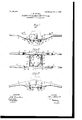
- Figure 1 is a side view of a carrier for barrels and the like embodying my improvements.
- Fig. 2 is a bottom plan view thereof, and
- Fig. 3 is also a side view showing the duplicate sets of handles in the position to which they are carried for the purpose of causing the clamping 'or grappling devices of the structure to take upon the sides of a barrel or the like for the purpose of lifting the same and carrying it from one place to another.
- I provide the carrier with duplicate sets of speciallyconstructed handles, with which are cooperatively organized specially-constructed clamping or grappling devices, between which the sides of a barrel or the like are received and tightly embraced for the purpose of enabling the barrel to be lifted from the ground or other support and carried from one place to another.
- the device or structure is admirably adapted for use by bricklayers, masons,
- 1 and 2 represent handles of duplicate sets, those of each set being preferably connected at 3 by means of a rung or in any other suitable way, while the adjacent ends of the handles of the two sets are pivotally joined together in any suitable way at 4, by which they may be carried either to substantially a true horizontal position with reference toeach other, as indicated in Fig. 1, or to a downward inclination with reference to each other, as indicated in Fig.
- connection herein shown being preferably by means of .a tenon 5, formed at the inner end of one of the handles of each set, fitting and working in a corresponding mortise 6, formed in the inner end of the corresponding handle of the other set, pivots 7 being employed for uniting the corresponding handles, as shown.
- suitable pins or other devices 11 to which are fastened or secured in any suitable manner oppositely-disposed curved or segmental members 12, the extremities of which have connected thereto at 13 the crossed inner extremities of sets of suitable rods 14, the outer ends of which are loosely connected at 15 to the under sides or edges of the handles of the two sets, hereinbefore referred to.
- the inner edges of each of the said handles in which is formed the mortise is beveled downwardly and outwardly in the direction of the free ends of the handles, as indicated at 16, although it is apparent that other means may be resorted to for this purpose.
- the sets of parallel rods 14 may be substituted by strong wires, if desired; ut for purposes of strength and certainty of operation I prefer the use of said rods, it being noted in Fig. 2' that in order to derive a free and uninterrupted working between the sets thereof the rods of one of the sets arebent outwardly, as indicated at 17, by which to provide a clearance for the portions of the rods of the other set crossing therewith.
- a carrier for barrels and the like comprising duplicate sets of pivotally-connected handles adapted to be carried to a downward inclination with reference to each other, segmental grappling members loosely suspended therefrom, and sets of rods crossing each other and movably connected at their ends to the ends of said segmental members and the under sides of the handles of each set, respectively.
- a carrier for barrels and the like comprising duplicate sets of handles constructed at their adjacent ends with mortise-and-tenon joints and connected by a pivot, the inner ends of the handles of one set being beveled downwardly and outwardly, loosely supported segmental grappling members occupying a position beneath the lower edges of the handles, and means loosely connecting the ends of each of said members with the under side of the handles of the set opposite thereto.
- a carrier for barrels and the like comprising duplicate sets .of handles constructed at their adjacent ends with mortise-and-tenon joints and connected by a pivot, the inner ends of the handles of one set being beveled downwardly and outwardly, loosely supported segmental grappling members occupying a position beneath the lower edges of the handles, and crossed rods loosely connecting the ends of each of said members with the under side of the handles of the set opposite thereto.
- a carrier for barrels and the like comprising duplicate sets of handles constructed at their adjacent ends with mortise-and-tenon joints and connected by a pivot, the inner ends of the handles of one set being beveled downwardly and outwardly, loosely supported segmental grappling members occupying a position beneath the lower edges of the handles, and'crossed rods loosely connecting the .ends of each of said members with the under side of the handles of the set opposite thereto, portions of the rods of one set being bent to provide clearance for corresponding portions of the rods of the other set.
Landscapes
- Table Equipment (AREA)
Description
PATENTED JAN. 2, 1906.
J. MITCHELL. CARRIER FOR BARRELS AND THE LIKE.
APPLICATION FILED MAY 24, 1905.
INVE/V T0? .272 22 Jfiicie'ZZ WITNESSES.
ATTORNEYS UNITED STATES PATENT OFFICE.
Specification of Letters Patent.
Patented Jan. 2, 1906.
Application filed May 24, 1905. Serial No- 262,004.
T0 to whom it may concern:
Be it known that I, J oHN MrrcHELL, a citizen of the United States, and a resident of Dannemora, in the county of Clinton and State of New York, have invented a new and Improved Carrier for Barrels and the Like,
of which the following is a full, clear, and eX- act description.
This invention relates to carriers for barrels and'the like; and it consists substantially in the details of construction and combinations of parts hereinafter more particularly described, and pointed out in the claims.
One of the-principal. objects of the invention is to provide a structure of this kind of an embodiment to overcome numerous disadvantages and objections encountered in the use of many other structures hitherto devised for similar purposes.
A further object is toprovide a' device or structure of the character referred to which is exceedingly simple in construction and comparatively inexpensive to manufacture, besides being strong and durable and not liable to get out of order, thoroughly effective and reliable for its purposes, and possessing the capacity for long and repeated service.
The above and additional objects are attained by means substantially such as are illustrated in the accompanying drawings, forming a part of this specification, in which similar characters of reference indicate corresponding parts in all the views.
Figure 1 is a side view of a carrier for barrels and the like embodying my improvements. Fig. 2 is a bottom plan view thereof, and Fig. 3 is also a side view showing the duplicate sets of handles in the position to which they are carried for the purpose of causing the clamping 'or grappling devices of the structure to take upon the sides of a barrel or the like for the purpose of lifting the same and carrying it from one place to another.
Before proceeding with a more detailed description it may be stated that in the form of my improvements herein shown I provide the carrier with duplicate sets of speciallyconstructed handles, with which are cooperatively organized specially-constructed clamping or grappling devices, between which the sides of a barrel or the like are received and tightly embraced for the purpose of enabling the barrel to be lifted from the ground or other support and carried from one place to another. The device or structure is admirably adapted for use by bricklayers, masons,
and other mechanics having to carry barrels of sand, cement, and simllar materials from place to place under the ordinaryrequirements of their tradesas, for instance, when engaged in the erection of a building or the construction of a sewer, &c.
While I, have herein represented my improvements in a certain preferred emb0di-. ment, it will be understood, of course, that I do not limit myself thereto in precise detail, since immaterial changes therein may be resorted to coming within the scope of my invention.
Reference being had to the drawings by the designating characters thereon, 1 and 2 represent handles of duplicate sets, those of each set being preferably connected at 3 by means of a rung or in any other suitable way, while the adjacent ends of the handles of the two sets are pivotally joined together in any suitable way at 4, by which they may be carried either to substantially a true horizontal position with reference toeach other, as indicated in Fig. 1, or to a downward inclination with reference to each other, as indicated in Fig. 3, the form of connection herein shown being preferably by means of .a tenon 5, formed at the inner end of one of the handles of each set, fitting and working in a corresponding mortise 6, formed in the inner end of the corresponding handle of the other set, pivots 7 being employed for uniting the corresponding handles, as shown.
Suspended from each of the rungs 3 by means of pins 8 passing therethrough (see Figs. 1 and 3) is a pair or set of links 9, to the lower ends of which are loosely connected at 10 suitable pins or other devices 11, to which are fastened or secured in any suitable manner oppositely-disposed curved or segmental members 12, the extremities of which have connected thereto at 13 the crossed inner extremities of sets of suitable rods 14, the outer ends of which are loosely connected at 15 to the under sides or edges of the handles of the two sets, hereinbefore referred to. To permit of the handles of the two sets being carried to a downward inclination with respect to each other, Fig. 3, the inner edges of each of the said handles in which is formed the mortise is beveled downwardly and outwardly in the direction of the free ends of the handles, as indicated at 16, although it is apparent that other means may be resorted to for this purpose.
From the foregoing it will be seen that when the sets of handles are carried to inclined positions with relation to each other the segmental members 12 will be carried apart or separated from each other for some distance, and then by slipping the structure downwardly over a barrel or the like, so as to bring the said segmental members on opposite sides thereof, the said barrel will be firmly clamped between or grappled by the segmental members on carrying the sets of handles upwardly to the horizontal position. (Shown in Fig. 1.) To transport the barrel from one place to another, it is simply necessary to carry it in the ordinary way by grasping the free ends of the handles thereof, and to again deposit the barrel upon the ground or other supporting-surface it is simply necessary to seat the same thereon at its lower end and again carry the sets .of handles downwardly, which'releases the clamping or grape pling devices and enables the structure to be lifted entirely free of the barrel, all of which, it is thought, will be quite apparent from the drawings.
The sets of parallel rods 14 ma be substituted by strong wires, if desired; ut for purposes of strength and certainty of operation I prefer the use of said rods, it being noted in Fig. 2' that in order to derive a free and uninterrupted working between the sets thereof the rods of one of the sets arebent outwardly, as indicated at 17, by which to provide a clearance for the portions of the rods of the other set crossing therewith.
As a means for enabling the structure to be raised or elevated to any desired height with a barrel clamped between the segmental members 12 thereof I prefer in some instances to'provide the handles 1 and 2 with pulleys or rings 17, Fig. 1, around or throu h which hoisting cables or chains may be passed in an obvious manner.
Having thus described my invention, I claim as new and desire to secure by Letters Patent 1 1 1. A carrier for barrels and the like comprising duplicate sets of pivotally-connected handles adapted to be carried to a downward inclination with reference to each other, segmental grappling members loosely suspended therefrom, and sets of rods crossing each other and movably connected at their ends to the ends of said segmental members and the under sides of the handles of each set, respectively.
2. A carrier for barrels and the like comprising duplicate sets of handles constructed at their adjacent ends with mortise-and-tenon joints and connected by a pivot, the inner ends of the handles of one set being beveled downwardly and outwardly, loosely supported segmental grappling members occupying a position beneath the lower edges of the handles, and means loosely connecting the ends of each of said members with the under side of the handles of the set opposite thereto.
3. A carrier for barrels and the like comprising duplicate sets .of handles constructed at their adjacent ends with mortise-and-tenon joints and connected by a pivot, the inner ends of the handles of one set being beveled downwardly and outwardly, loosely supported segmental grappling members occupying a position beneath the lower edges of the handles, and crossed rods loosely connecting the ends of each of said members with the under side of the handles of the set opposite thereto. j
4. A carrier for barrels and the like comprising duplicate sets of handles constructed at their adjacent ends with mortise-and-tenon joints and connected by a pivot, the inner ends of the handles of one set being beveled downwardly and outwardly, loosely supported segmental grappling members occupying a position beneath the lower edges of the handles, and'crossed rods loosely connecting the .ends of each of said members with the under side of the handles of the set opposite thereto, portions of the rods of one set being bent to provide clearance for corresponding portions of the rods of the other set.
In testimony whereof I have signed my name to this specification in the presence of two subscribing witnesses.
' JOHN MITCHELL.
Witnesses:
AMos T. BAKER, FRANK J. WEIGAND.
Priority Applications (1)
| Application Number | Priority Date | Filing Date | Title |
|---|---|---|---|
| US26200405A US809003A (en) | 1905-05-24 | 1905-05-24 | Carrier for barrels and the like. |
Applications Claiming Priority (1)
| Application Number | Priority Date | Filing Date | Title |
|---|---|---|---|
| US26200405A US809003A (en) | 1905-05-24 | 1905-05-24 | Carrier for barrels and the like. |
Publications (1)
| Publication Number | Publication Date |
|---|---|
| US809003A true US809003A (en) | 1906-01-02 |
Family
ID=2877484
Family Applications (1)
| Application Number | Title | Priority Date | Filing Date |
|---|---|---|---|
| US26200405A Expired - Lifetime US809003A (en) | 1905-05-24 | 1905-05-24 | Carrier for barrels and the like. |
Country Status (1)
| Country | Link |
|---|---|
| US (1) | US809003A (en) |
Cited By (4)
| Publication number | Priority date | Publication date | Assignee | Title |
|---|---|---|---|---|
| US2416483A (en) * | 1944-12-01 | 1947-02-25 | Jack I Hope | Milk can truck |
| US5009558A (en) * | 1989-11-16 | 1991-04-23 | Savedra Jr Emilio | Tree lifter |
| US20050057056A1 (en) * | 2003-09-19 | 2005-03-17 | Davis Daniel M. | Object lifting device that converts opposing angled lifting forces to girthing forces |
| US20140265383A1 (en) * | 2013-03-15 | 2014-09-18 | Michael James | Landscaping Carrier |
-
1905
- 1905-05-24 US US26200405A patent/US809003A/en not_active Expired - Lifetime
Cited By (6)
| Publication number | Priority date | Publication date | Assignee | Title |
|---|---|---|---|---|
| US2416483A (en) * | 1944-12-01 | 1947-02-25 | Jack I Hope | Milk can truck |
| US5009558A (en) * | 1989-11-16 | 1991-04-23 | Savedra Jr Emilio | Tree lifter |
| US20050057056A1 (en) * | 2003-09-19 | 2005-03-17 | Davis Daniel M. | Object lifting device that converts opposing angled lifting forces to girthing forces |
| US7182379B2 (en) | 2003-09-19 | 2007-02-27 | Daniel M Davis | Object lifting device that converts opposing angled lifting forces to girthing forces |
| US20140265383A1 (en) * | 2013-03-15 | 2014-09-18 | Michael James | Landscaping Carrier |
| US8905447B2 (en) * | 2013-03-15 | 2014-12-09 | Michael James | Landscaping carrier |
Similar Documents
| Publication | Publication Date | Title |
|---|---|---|
| US809003A (en) | Carrier for barrels and the like. | |
| US936681A (en) | Ladder. | |
| US1231823A (en) | Silo-scaffolding. | |
| US580737A (en) | Thomas mcglotiilin smith | |
| US999017A (en) | Door-holder. | |
| US311478A (en) | Anthony flansburgh | |
| US123825A (en) | Improvement in steamboat-chimneys | |
| US1081902A (en) | Frame for tents. | |
| US567642A (en) | Fire-escape | |
| US896758A (en) | Apparatus for handling drain-tile. | |
| US1055264A (en) | Well-lining. | |
| US910062A (en) | Grapple. | |
| US473768A (en) | Ladder | |
| US905208A (en) | Portable swinging derrick. | |
| US658939A (en) | Lever-derrick. | |
| US705383A (en) | Carrier. | |
| US725169A (en) | Building-block grapple. | |
| US1185627A (en) | Pipe-lifting device. | |
| US1207219A (en) | Rail-clamp. | |
| US891796A (en) | Steel derrick and excavating-machine. | |
| US185203A (en) | Improvement in extension-ladders | |
| US578479A (en) | Device for lifting | |
| US213544A (en) | Improvement in fire-escape ladders | |
| US312789A (en) | Feedebick u | |
| US465157A (en) | Hay-stacker |