US8089618B2 - Laser distance measuring device - Google Patents
Laser distance measuring device Download PDFInfo
- Publication number
- US8089618B2 US8089618B2 US12/590,366 US59036609A US8089618B2 US 8089618 B2 US8089618 B2 US 8089618B2 US 59036609 A US59036609 A US 59036609A US 8089618 B2 US8089618 B2 US 8089618B2
- Authority
- US
- United States
- Prior art keywords
- distance measuring
- measuring device
- laser
- laser distance
- optical filter
- Prior art date
- Legal status (The legal status is an assumption and is not a legal conclusion. Google has not performed a legal analysis and makes no representation as to the accuracy of the status listed.)
- Expired - Fee Related, expires
Links
- 230000003287 optical effect Effects 0.000 claims abstract description 71
- 230000003595 spectral effect Effects 0.000 claims abstract description 26
- 238000006243 chemical reaction Methods 0.000 claims abstract description 9
- 238000001914 filtration Methods 0.000 claims description 6
- 239000012788 optical film Substances 0.000 claims description 4
- 238000005259 measurement Methods 0.000 description 11
- 230000033228 biological regulation Effects 0.000 description 3
- 239000011248 coating agent Substances 0.000 description 1
- 238000000576 coating method Methods 0.000 description 1
- 238000010276 construction Methods 0.000 description 1
- 238000005034 decoration Methods 0.000 description 1
- 230000007423 decrease Effects 0.000 description 1
- 230000003247 decreasing effect Effects 0.000 description 1
- 238000011161 development Methods 0.000 description 1
- 238000010586 diagram Methods 0.000 description 1
- 239000000463 material Substances 0.000 description 1
- 238000012986 modification Methods 0.000 description 1
- 230000004048 modification Effects 0.000 description 1
- 238000012545 processing Methods 0.000 description 1
- 238000011160 research Methods 0.000 description 1
Images
Classifications
-
- G—PHYSICS
- G01—MEASURING; TESTING
- G01S—RADIO DIRECTION-FINDING; RADIO NAVIGATION; DETERMINING DISTANCE OR VELOCITY BY USE OF RADIO WAVES; LOCATING OR PRESENCE-DETECTING BY USE OF THE REFLECTION OR RERADIATION OF RADIO WAVES; ANALOGOUS ARRANGEMENTS USING OTHER WAVES
- G01S7/00—Details of systems according to groups G01S13/00, G01S15/00, G01S17/00
- G01S7/48—Details of systems according to groups G01S13/00, G01S15/00, G01S17/00 of systems according to group G01S17/00
- G01S7/481—Constructional features, e.g. arrangements of optical elements
- G01S7/4811—Constructional features, e.g. arrangements of optical elements common to transmitter and receiver
-
- G—PHYSICS
- G01—MEASURING; TESTING
- G01S—RADIO DIRECTION-FINDING; RADIO NAVIGATION; DETERMINING DISTANCE OR VELOCITY BY USE OF RADIO WAVES; LOCATING OR PRESENCE-DETECTING BY USE OF THE REFLECTION OR RERADIATION OF RADIO WAVES; ANALOGOUS ARRANGEMENTS USING OTHER WAVES
- G01S17/00—Systems using the reflection or reradiation of electromagnetic waves other than radio waves, e.g. lidar systems
- G01S17/02—Systems using the reflection of electromagnetic waves other than radio waves
- G01S17/06—Systems determining position data of a target
- G01S17/08—Systems determining position data of a target for measuring distance only
- G01S17/32—Systems determining position data of a target for measuring distance only using transmission of continuous waves, whether amplitude-, frequency-, or phase-modulated, or unmodulated
- G01S17/36—Systems determining position data of a target for measuring distance only using transmission of continuous waves, whether amplitude-, frequency-, or phase-modulated, or unmodulated with phase comparison between the received signal and the contemporaneously transmitted signal
-
- G—PHYSICS
- G01—MEASURING; TESTING
- G01S—RADIO DIRECTION-FINDING; RADIO NAVIGATION; DETERMINING DISTANCE OR VELOCITY BY USE OF RADIO WAVES; LOCATING OR PRESENCE-DETECTING BY USE OF THE REFLECTION OR RERADIATION OF RADIO WAVES; ANALOGOUS ARRANGEMENTS USING OTHER WAVES
- G01S7/00—Details of systems according to groups G01S13/00, G01S15/00, G01S17/00
- G01S7/48—Details of systems according to groups G01S13/00, G01S15/00, G01S17/00 of systems according to group G01S17/00
- G01S7/481—Constructional features, e.g. arrangements of optical elements
- G01S7/4814—Constructional features, e.g. arrangements of optical elements of transmitters alone
-
- G—PHYSICS
- G01—MEASURING; TESTING
- G01S—RADIO DIRECTION-FINDING; RADIO NAVIGATION; DETERMINING DISTANCE OR VELOCITY BY USE OF RADIO WAVES; LOCATING OR PRESENCE-DETECTING BY USE OF THE REFLECTION OR RERADIATION OF RADIO WAVES; ANALOGOUS ARRANGEMENTS USING OTHER WAVES
- G01S17/00—Systems using the reflection or reradiation of electromagnetic waves other than radio waves, e.g. lidar systems
- G01S17/02—Systems using the reflection of electromagnetic waves other than radio waves
- G01S17/06—Systems determining position data of a target
- G01S17/08—Systems determining position data of a target for measuring distance only
- G01S17/32—Systems determining position data of a target for measuring distance only using transmission of continuous waves, whether amplitude-, frequency-, or phase-modulated, or unmodulated
Definitions
- the present invention relates to a laser distance measuring device, and more particularly to a hand-held laser distance measuring device.
- Laser distance measuring devices have been widely used in construction, interior decoration and other fields due to their high accuracy of measurement. They have a measuring range up to tens of meters and are usually designed to be handheld devices.
- the general principles of measurement are as follows: an emitter emits an intensity modulated measuring beam to an object to be measured; the measuring beam is reflected or scattered by the object and is picked up by a photoreceiver and the distance from the object to be measured is determined based on the phase position of the modulated measuring beam relative to the emitter.
- a filter device with a predetermined bandwidth is usually arranged in front of the photoreceiver.
- the modulated measuring beam emitted by the emitter has a bandwidth less than the bandwidth of the filter device so that both the measuring beam reflected by the object and some disturbing light, or noise, within the bandwidth of the filter is received by the photoreceiver, while most of the disturbing light is filtered out by the filter device.
- the intensity of the disturbing light in the background increases.
- the disturbing light received by the photoreceiver increases and the signal to noise ratio (the ratio of the reflected measuring beam signals received by the photoreceiver to the disturbing light signals received by the photoreceiver) decreases, which results in both the ranging capability and effective measurement distance of the laser distance measuring device decreasing when compared to the indoor measurement capabilities.
- the bandwidth of the filter device can be narrowed to filter out more of the noise signals (i.e., the disturbing light signals), however, additional useful portions of the measuring beam signal will also be filtered out if the bandwidth of the filter device is narrowed.
- the signal to noise ratio is not effectively improved.
- the emitting power of the laser distance measuring device there is a limit to the emitting power of the laser distance measuring device.
- the upper limit of the maximum power is 1 mW. Accordingly, the ranging capability of the laser distance measuring device cannot be improved by arbitrarily increasing the emitting power of the emitter.
- the present invention provides a laser distance measuring device having a higher signal to noise ratio, specifically, a laser distance measuring device with an enhanced ranging capability under a bright or strong light environment.
- the present invention provides a laser distance measuring device which has an emitting part arranged on an emitting optical path that emits a measuring beam to an object to be measured.
- the emitting part comprises a laser generating device for emitting a laser beam with a first spectral bandwidth using a collimating lens.
- the emitting part also has an optical filter with a second spectral bandwidth which is less than the first spectral bandwidth.
- the laser distance measuring device also includes a receiving part arranged on a receiving optical path.
- the receiving part comprises a receiving object and a photoelectric receiving and conversion device which receives the measuring beam reflected by the object to be measured and converts it into an electric signal.
- the laser distance measuring device disclosed in the present invention has an optical filter having a spectral bandwidth less than the spectral bandwidth of the laser beam. This allows the non-necessary portions of the laser beam emitted from the laser generating device to be filtered out by the optical filter.
- the proportion of the useful measuring beam of the laser beam emitted from the laser generating device can be improved within the limits of the maximum emitting power allowed by safety regulations, and the power of the useful portions of the measuring beam emitted from the optical filter can be close to or equal to the upper limit of the maximum power allowed by safety regulations.
- the signal to noise ratio is improved and the ranging capability of the laser distance measuring device under a bright or strong light environment is enhanced.
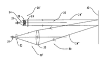
- FIG. 1 schematically shows an optical path of a distance measurement of a laser distance measuring device according to a preferred embodiment of the present invention.
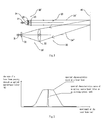
- FIG. 2 is a graphic diagram of a spectral bandwidth of an optical narrow-band filter on an emitting optical path and a spectral bandwidth of a laser beam according to the FIG. 1 .
- a laser distance measuring device of a preferred embodiment of the present invention comprises an emitting part 20 ′ arranged on an emitting optical path 20 and a receiving part 30 ′ arranged on a receiving optical path 30 .
- the emitting part 20 ′ includes a laser transmitter 21 , a collimating lens group 22 and an optical narrow-band filter 23 .
- the receiving part 30 ′ includes a photoelectric receiving and conversion device 31 , an optical narrow-band filter 32 and a convergent lens 33 .
- the laser transmitter 21 emits a laser beam 24 .
- the laser beam 24 is collimated into a collimated laser beam by the collimating lens group 22 .
- the collimated laser beam is then filtered using the optical narrow-band filter 23 , and a measuring laser beam 24 ′ is produced and emitted from the laser distance measuring device.
- the measuring laser beam 24 ′ is reflected or scattered by an object 40 to be measured.
- a reflected laser beam 24 ′′ is converged by the convergent lens 33 which is used as a receiving objective and is filtered by the optical narrow-band filter 32 which is arranged between the photoelectric receiving and conversion device 31 and the convergent lens 33 .
- the reflected laser beam 24 ′′ is received by the photoelectric receiving and conversion device 31 and is converted into corresponding electrical signals.
- the electrical signals containing the distance measurement information are transmitted to a signal processor (not shown in the figure), and the distance between the laser distance measuring device and the object 40 is calculated by the signal processor using the electrical signals.
- the optical narrow-band filter 23 arranged in the emitting optical path 20 has a spectral bandwidth which is less than a spectral bandwidth of the laser beam 24 .
- the laser emitting power of the laser distance measuring device is the emitting power of the measuring laser beam 24 ′.
- the power of the laser beam within the bandwidth of the optical narrow-band filter 23 i.e.
- the power of the measuring laser beam 24 ′ can be improved by adjusting the emitting power of the laser transmitter 21 so that the intensity of effective laser signals is improved as much as possible under the premise that the emitting power of the measuring laser beam 24 ′ does not exceed an upper limit of the maximum power prescribed by safety regulations.
- the power of the laser beam with the bandwidth of the optical narrow-band filter 23 is improved, the signal to noise ratio is also improved.
- the optical narrow-band filter 32 is arranged on the receiving optical path 30 and is used to filter out the disturbing light signals in the measurement environment, so that the disturbing light signals outside the bandwidth of the optical narrow-band filter 32 are filtered out. Because of the increased measurement distance of the present invention, the intensity of the reflected laser beam is weakened exponentially. To improve the signal to noise ratio of the electrical signals received by the photoelectric receiving and conversion device 31 and improve the maximum measurement distance at the same time, the energy loss of reflected laser beam 24 ′′ should be minimized as much as possible.
- the bandwidth of the optical narrow-band filter 32 is set to be equal to the bandwidth of the optical narrow-band filter 23 .
- the bandwidth of the optical narrow-band filter 32 can be set narrower or wider than the bandwidth of the optical narrow-band filter 23 . If the bandwidth of the optical narrow-band filter 32 is less than the bandwidth of the optical narrow-band filter 23 , to filter out disturbing light signals more effectively, the ranging capability of the laser distance measuring device under the bright or strong light environment is enhanced. However, because part of the reflected laser beam 24 ′′ will also be filtered out, the maximum measurement distance is reduced compared to the preferred embodiment.
- the optical narrow-band filter 32 is made from substantially the same material as the optical narrow-band filter 23 , and they have similar filter characteristics and similar temperature drift characteristics.
- a collimating lens with a filtering function can be arranged in front of the laser transmitter 21 directly, so that the fixing of the optical narrow-band filter 23 is removed.
- a collimating lens with a filtering function can be obtained by coating the collimating lens group 22 mentioned above with a layer of optical film having a filtering function.
- the optical narrow-band filter 32 arranged on the receiving optical path 30 can also be removed using a convergent lens having a filtering function to replace the original ordinary convergent lens.
- optical narrow-band filter 23 can be encased within the laser transmitter 21 and the optical narrow-band filter 32 be encased within the photoelectric receiving and conversion device 31 . Also, a person skilled in the art understands that the optical narrow-band filter 23 or the optical film having a filtering function on the emitting optical path 20 can be arranged between the laser transmitter 21 and the collimating lens group 22 and may also be located on one side of the collimating lens group 22 which faces away from the laser transmitter 21 .
Landscapes
- Engineering & Computer Science (AREA)
- Physics & Mathematics (AREA)
- Computer Networks & Wireless Communication (AREA)
- General Physics & Mathematics (AREA)
- Radar, Positioning & Navigation (AREA)
- Remote Sensing (AREA)
- Electromagnetism (AREA)
- Optical Radar Systems And Details Thereof (AREA)
- Measurement Of Optical Distance (AREA)
Applications Claiming Priority (3)
| Application Number | Priority Date | Filing Date | Title |
|---|---|---|---|
| CN200820216153U | 2008-11-17 | ||
| CNU200820216153XU CN201298079Y (zh) | 2008-11-17 | 2008-11-17 | 激光测距装置 |
| CN200820216153.X | 2008-11-17 |
Publications (2)
| Publication Number | Publication Date |
|---|---|
| US20100123893A1 US20100123893A1 (en) | 2010-05-20 |
| US8089618B2 true US8089618B2 (en) | 2012-01-03 |
Family
ID=41044061
Family Applications (1)
| Application Number | Title | Priority Date | Filing Date |
|---|---|---|---|
| US12/590,366 Expired - Fee Related US8089618B2 (en) | 2008-11-17 | 2009-11-06 | Laser distance measuring device |
Country Status (5)
| Country | Link |
|---|---|
| US (1) | US8089618B2 (fr) |
| CN (1) | CN201298079Y (fr) |
| DE (1) | DE202009015321U1 (fr) |
| FR (1) | FR2938659B3 (fr) |
| GB (1) | GB2465274B (fr) |
Cited By (7)
| Publication number | Priority date | Publication date | Assignee | Title |
|---|---|---|---|---|
| US9992477B2 (en) | 2015-09-24 | 2018-06-05 | Ouster, Inc. | Optical system for collecting distance information within a field |
| US10063849B2 (en) | 2015-09-24 | 2018-08-28 | Ouster, Inc. | Optical system for collecting distance information within a field |
| US10222475B2 (en) | 2017-05-15 | 2019-03-05 | Ouster, Inc. | Optical imaging transmitter with brightness enhancement |
| US10222458B2 (en) | 2016-08-24 | 2019-03-05 | Ouster, Inc. | Optical system for collecting distance information within a field |
| US10481269B2 (en) | 2017-12-07 | 2019-11-19 | Ouster, Inc. | Rotating compact light ranging system |
| US10732032B2 (en) | 2018-08-09 | 2020-08-04 | Ouster, Inc. | Scanning sensor array with overlapping pass bands |
| US10739189B2 (en) | 2018-08-09 | 2020-08-11 | Ouster, Inc. | Multispectral ranging/imaging sensor arrays and systems |
Families Citing this family (9)
| Publication number | Priority date | Publication date | Assignee | Title |
|---|---|---|---|---|
| CN101870272A (zh) * | 2010-05-31 | 2010-10-27 | 暨南大学 | 基于激光数字测相的防车灯眩目系统及方法 |
| CN102278974B (zh) * | 2010-06-09 | 2013-04-17 | 南京德朔实业有限公司 | 激光测距装置 |
| WO2013013349A1 (fr) * | 2011-07-22 | 2013-01-31 | 江苏徕兹光电科技有限公司 | Structure de système optique de télémètre laser |
| CN102353353B (zh) * | 2011-10-08 | 2013-02-06 | 长春理工大学 | 无基线光环成像被动光学测距方法及装置 |
| DE102015224715A1 (de) * | 2015-12-09 | 2017-06-14 | Robert Bosch Gmbh | Sensorelement, Sensorvorrichtung und Verfahren |
| CN105842708A (zh) * | 2016-06-21 | 2016-08-10 | 昆山穿山甲机器人有限公司 | 抗背景光干扰的机器人光电测距防撞系统及方法 |
| CN108008399A (zh) * | 2016-10-28 | 2018-05-08 | 江苏徕兹测控科技有限公司 | 一种手持激光测距装置及其方法 |
| CN110729669B (zh) * | 2019-08-27 | 2020-11-03 | 东莞理工学院 | 基于相位式激光测距的电缆轴向切割系统及方法 |
| CN113687379B (zh) * | 2021-07-20 | 2024-07-26 | 国网内蒙古东部电力有限公司 | 降低接收光路背景杂散光干扰的系统及其降扰方法 |
Citations (4)
| Publication number | Priority date | Publication date | Assignee | Title |
|---|---|---|---|---|
| JPH08304546A (ja) * | 1995-04-28 | 1996-11-22 | Mitsubishi Heavy Ind Ltd | 光学式水中測長装置 |
| US6288383B1 (en) * | 1999-10-25 | 2001-09-11 | Rafael-Armament Development Authority Ltd. | Laser spot locating device and system |
| US7177015B2 (en) | 2002-12-26 | 2007-02-13 | Kabushiki Kaisha Topcon | Distance-measuring device |
| US20080094605A1 (en) | 2004-12-16 | 2008-04-24 | Ulrich Drodofsky | Laser-System |
Family Cites Families (7)
| Publication number | Priority date | Publication date | Assignee | Title |
|---|---|---|---|---|
| SE414347B (sv) * | 1974-11-20 | 1980-07-21 | Aga Ab | Anordning for att meta avstandet till en punkt pa den egenstralande innerveggen i en ugn |
| CH589856A5 (fr) * | 1975-12-29 | 1977-07-15 | Kern & Co Ag | |
| JPS58158377U (ja) * | 1982-04-19 | 1983-10-22 | 旭光学工業株式会社 | 光波距離計の切換シヤツタ− |
| JPS59126977A (ja) * | 1983-01-10 | 1984-07-21 | Mitsubishi Electric Corp | レ−ザ測距装置 |
| US5192978A (en) * | 1991-09-17 | 1993-03-09 | Kaman Aerospace Corporation | Apparatus and method for reducing solar noise in imaging lidar, underwater communications and lidar bathymetry systems |
| CN1779486A (zh) * | 2004-11-19 | 2006-05-31 | 南京德朔实业有限公司 | 激光测距装置 |
| CN2779424Y (zh) * | 2005-03-24 | 2006-05-10 | 南京德朔实业有限公司 | 测距装置 |
-
2008
- 2008-11-17 CN CNU200820216153XU patent/CN201298079Y/zh not_active Expired - Fee Related
-
2009
- 2009-11-06 US US12/590,366 patent/US8089618B2/en not_active Expired - Fee Related
- 2009-11-11 GB GB0919743.5A patent/GB2465274B/en not_active Expired - Fee Related
- 2009-11-12 DE DE202009015321U patent/DE202009015321U1/de not_active Expired - Lifetime
- 2009-11-16 FR FR0958062A patent/FR2938659B3/fr not_active Expired - Fee Related
Patent Citations (4)
| Publication number | Priority date | Publication date | Assignee | Title |
|---|---|---|---|---|
| JPH08304546A (ja) * | 1995-04-28 | 1996-11-22 | Mitsubishi Heavy Ind Ltd | 光学式水中測長装置 |
| US6288383B1 (en) * | 1999-10-25 | 2001-09-11 | Rafael-Armament Development Authority Ltd. | Laser spot locating device and system |
| US7177015B2 (en) | 2002-12-26 | 2007-02-13 | Kabushiki Kaisha Topcon | Distance-measuring device |
| US20080094605A1 (en) | 2004-12-16 | 2008-04-24 | Ulrich Drodofsky | Laser-System |
Cited By (34)
| Publication number | Priority date | Publication date | Assignee | Title |
|---|---|---|---|---|
| US9992477B2 (en) | 2015-09-24 | 2018-06-05 | Ouster, Inc. | Optical system for collecting distance information within a field |
| US11178381B2 (en) | 2015-09-24 | 2021-11-16 | Ouster, Inc. | Optical system for collecting distance information within a field |
| US11190750B2 (en) | 2015-09-24 | 2021-11-30 | Ouster, Inc. | Optical imaging system with a plurality of sense channels |
| US11202056B2 (en) | 2015-09-24 | 2021-12-14 | Ouster, Inc. | Optical system with multiple light emitters sharing a field of view of a pixel detector |
| US11956410B2 (en) | 2015-09-24 | 2024-04-09 | Ouster, Inc. | Optical system for collecting distance information within a field |
| US11627298B2 (en) | 2015-09-24 | 2023-04-11 | Ouster, Inc. | Optical system for collecting distance information within a field |
| US11025885B2 (en) | 2015-09-24 | 2021-06-01 | Ouster, Inc. | Optical system for collecting distance information within a field |
| US11196979B2 (en) | 2015-09-24 | 2021-12-07 | Ouster, Inc. | Optical system for collecting distance information within a field |
| US10063849B2 (en) | 2015-09-24 | 2018-08-28 | Ouster, Inc. | Optical system for collecting distance information within a field |
| US10948572B2 (en) | 2016-08-24 | 2021-03-16 | Ouster, Inc. | Optical system for collecting distance information within a field |
| US10809359B2 (en) | 2016-08-24 | 2020-10-20 | Ouster, Inc. | Optical system for collecting distance information within a field |
| US11422236B2 (en) | 2016-08-24 | 2022-08-23 | Ouster, Inc. | Optical system for collecting distance information within a field |
| US10222458B2 (en) | 2016-08-24 | 2019-03-05 | Ouster, Inc. | Optical system for collecting distance information within a field |
| US10222475B2 (en) | 2017-05-15 | 2019-03-05 | Ouster, Inc. | Optical imaging transmitter with brightness enhancement |
| US10663586B2 (en) | 2017-05-15 | 2020-05-26 | Ouster, Inc. | Optical imaging transmitter with brightness enhancement |
| US11086013B2 (en) | 2017-05-15 | 2021-08-10 | Ouster, Inc. | Micro-optics for imaging module with multiple converging lenses per channel |
| US11131773B2 (en) | 2017-05-15 | 2021-09-28 | Ouster, Inc. | Lidar unit with an optical link between controller and photosensor layer |
| US11150347B2 (en) | 2017-05-15 | 2021-10-19 | Ouster, Inc. | Micro-optics for optical imager with non-uniform filter |
| US11175405B2 (en) | 2017-05-15 | 2021-11-16 | Ouster, Inc. | Spinning lidar unit with micro-optics aligned behind stationary window |
| US11340336B2 (en) | 2017-12-07 | 2022-05-24 | Ouster, Inc. | Rotating light ranging system with optical communication uplink and downlink channels |
| US20200025879A1 (en) | 2017-12-07 | 2020-01-23 | Ouster, Inc. | Light ranging system with opposing circuit boards |
| US11994618B2 (en) | 2017-12-07 | 2024-05-28 | Ouster, Inc. | Rotating compact light ranging system |
| US11287515B2 (en) | 2017-12-07 | 2022-03-29 | Ouster, Inc. | Rotating compact light ranging system comprising a stator driver circuit imparting an electromagnetic force on a rotor assembly |
| US11300665B2 (en) | 2017-12-07 | 2022-04-12 | Ouster, Inc. | Rotating compact light ranging system |
| US10481269B2 (en) | 2017-12-07 | 2019-11-19 | Ouster, Inc. | Rotating compact light ranging system |
| US11353556B2 (en) | 2017-12-07 | 2022-06-07 | Ouster, Inc. | Light ranging device with a multi-element bulk lens system |
| US10969490B2 (en) | 2017-12-07 | 2021-04-06 | Ouster, Inc. | Light ranging system with opposing circuit boards |
| US11473969B2 (en) | 2018-08-09 | 2022-10-18 | Ouster, Inc. | Channel-specific micro-optics for optical arrays |
| US11473970B2 (en) | 2018-08-09 | 2022-10-18 | Ouster, Inc. | Subpixel apertures for channels in a scanning sensor array |
| US10732032B2 (en) | 2018-08-09 | 2020-08-04 | Ouster, Inc. | Scanning sensor array with overlapping pass bands |
| US11733092B2 (en) | 2018-08-09 | 2023-08-22 | Ouster, Inc. | Channel-specific micro-optics for optical arrays |
| US10739189B2 (en) | 2018-08-09 | 2020-08-11 | Ouster, Inc. | Multispectral ranging/imaging sensor arrays and systems |
| US10760957B2 (en) | 2018-08-09 | 2020-09-01 | Ouster, Inc. | Bulk optics for a scanning array |
| US12072237B2 (en) | 2018-08-09 | 2024-08-27 | Ouster, Inc. | Multispectral ranging and imaging systems |
Also Published As
| Publication number | Publication date |
|---|---|
| FR2938659B3 (fr) | 2011-04-01 |
| GB0919743D0 (en) | 2009-12-30 |
| US20100123893A1 (en) | 2010-05-20 |
| FR2938659A3 (fr) | 2010-05-21 |
| DE202009015321U1 (de) | 2010-05-12 |
| GB2465274A (en) | 2010-05-19 |
| CN201298079Y (zh) | 2009-08-26 |
| GB2465274B (en) | 2012-11-28 |
Similar Documents
| Publication | Publication Date | Title |
|---|---|---|
| US8089618B2 (en) | Laser distance measuring device | |
| US7834984B2 (en) | Device for optical distance measurement | |
| US6833909B2 (en) | Device for optical distance measurement of distance over a large measuring range | |
| US9322992B2 (en) | Devices and methods for multimode light detection | |
| JP2020513557A (ja) | 光学的粒子センサーモジュール | |
| JP5209455B2 (ja) | レーザ距離測定器 | |
| US6437854B2 (en) | Radar system for determining optical visual range | |
| WO2007020780A8 (fr) | Dispositif de mesure | |
| KR101581061B1 (ko) | 물체 검출을 위한 광 배리어 및 방법 | |
| JPWO2012115083A1 (ja) | 空間情報検出装置 | |
| CN109799510A (zh) | 距离测量传感器 | |
| WO2012089957A1 (fr) | Dispositif de detection d'une direction angulaire dans laquelle se trouve un objet | |
| US8395759B2 (en) | Device for optical distance measurement | |
| CN110914706B (zh) | Lidar测量装置 | |
| KR20200102900A (ko) | 라이다 장치 | |
| CN108387902A (zh) | 一种光测距方法及设备 | |
| US3898007A (en) | Device for electro-optical distance measurement | |
| JP2011096724A (ja) | 反射型光結合装置および電子機器 | |
| US20180335304A1 (en) | Light receiver for position referencing | |
| KR102669349B1 (ko) | 판독장치 및 넌스캐닝 라이다 측정장치 | |
| JP2006053055A (ja) | レーザ測定装置 | |
| TWI235230B (en) | Optical fixed-distance sensing apparatus | |
| JPH04283683A (ja) | 光波測距装置 | |
| JP4229793B2 (ja) | 光学式距離計測装置 | |
| CN110988900B (zh) | 一种具备测温功能的光量子测距仪及测温测距方法 |
Legal Events
| Date | Code | Title | Description |
|---|---|---|---|
| AS | Assignment |
Owner name: CHERVON LIMITED,HONG KONG Free format text: ASSIGNMENT OF ASSIGNORS INTEREST;ASSIGNOR:WANG, DEZHONG;REEL/FRAME:023687/0297 Effective date: 20091105 Owner name: CHERVON LIMITED, HONG KONG Free format text: ASSIGNMENT OF ASSIGNORS INTEREST;ASSIGNOR:WANG, DEZHONG;REEL/FRAME:023687/0297 Effective date: 20091105 |
|
| AS | Assignment |
Owner name: CHERVON LIMITED,HONG KONG Free format text: CORRECTIVE ASSIGNMENT TO CORRECT THE SPELLING OF THE INVENTOR'S NAME TO READ DEZHONG YANG INSTEAD OF DEZHONG WANG PREVIOUSLY RECORDED ON REEL 023687 FRAME 0297. ASSIGNOR(S) HEREBY CONFIRMS THE ASSIGNMENT OF U.S. PATENT APPLICATION NO. 12/590,366 FROM DEZHONG YANG TO CHERVON LIMITED.;ASSIGNOR:YANG, DEZHONG;REEL/FRAME:023771/0942 Effective date: 20091105 Owner name: CHERVON LIMITED, HONG KONG Free format text: CORRECTIVE ASSIGNMENT TO CORRECT THE SPELLING OF THE INVENTOR'S NAME TO READ DEZHONG YANG INSTEAD OF DEZHONG WANG PREVIOUSLY RECORDED ON REEL 023687 FRAME 0297. ASSIGNOR(S) HEREBY CONFIRMS THE ASSIGNMENT OF U.S. PATENT APPLICATION NO. 12/590,366 FROM DEZHONG YANG TO CHERVON LIMITED.;ASSIGNOR:YANG, DEZHONG;REEL/FRAME:023771/0942 Effective date: 20091105 |
|
| STCF | Information on status: patent grant |
Free format text: PATENTED CASE |
|
| FPAY | Fee payment |
Year of fee payment: 4 |
|
| AS | Assignment |
Owner name: CHERVON (HK) LIMITED, HONG KONG Free format text: ASSIGNMENT OF ASSIGNORS INTEREST;ASSIGNOR:CHERVON LIMITED;REEL/FRAME:038333/0750 Effective date: 20160415 |
|
| FEPP | Fee payment procedure |
Free format text: MAINTENANCE FEE REMINDER MAILED (ORIGINAL EVENT CODE: REM.); ENTITY STATUS OF PATENT OWNER: LARGE ENTITY |
|
| LAPS | Lapse for failure to pay maintenance fees |
Free format text: PATENT EXPIRED FOR FAILURE TO PAY MAINTENANCE FEES (ORIGINAL EVENT CODE: EXP.); ENTITY STATUS OF PATENT OWNER: LARGE ENTITY |
|
| STCH | Information on status: patent discontinuation |
Free format text: PATENT EXPIRED DUE TO NONPAYMENT OF MAINTENANCE FEES UNDER 37 CFR 1.362 |
|
| FP | Lapsed due to failure to pay maintenance fee |
Effective date: 20200103 |