US8077549B2 - Frontal sonar - Google Patents
Frontal sonar Download PDFInfo
- Publication number
- US8077549B2 US8077549B2 US12/301,092 US30109207A US8077549B2 US 8077549 B2 US8077549 B2 US 8077549B2 US 30109207 A US30109207 A US 30109207A US 8077549 B2 US8077549 B2 US 8077549B2
- Authority
- US
- United States
- Prior art keywords
- sonar
- antenna
- insonification
- sectors
- image
- Prior art date
- Legal status (The legal status is an assumption and is not a legal conclusion. Google has not performed a legal analysis and makes no representation as to the accuracy of the status listed.)
- Active, expires
Links
Images


Classifications
-
- G—PHYSICS
- G01—MEASURING; TESTING
- G01S—RADIO DIRECTION-FINDING; RADIO NAVIGATION; DETERMINING DISTANCE OR VELOCITY BY USE OF RADIO WAVES; LOCATING OR PRESENCE-DETECTING BY USE OF THE REFLECTION OR RERADIATION OF RADIO WAVES; ANALOGOUS ARRANGEMENTS USING OTHER WAVES
- G01S15/00—Systems using the reflection or reradiation of acoustic waves, e.g. sonar systems
- G01S15/88—Sonar systems specially adapted for specific applications
- G01S15/89—Sonar systems specially adapted for specific applications for mapping or imaging
-
- G—PHYSICS
- G01—MEASURING; TESTING
- G01S—RADIO DIRECTION-FINDING; RADIO NAVIGATION; DETERMINING DISTANCE OR VELOCITY BY USE OF RADIO WAVES; LOCATING OR PRESENCE-DETECTING BY USE OF THE REFLECTION OR RERADIATION OF RADIO WAVES; ANALOGOUS ARRANGEMENTS USING OTHER WAVES
- G01S7/00—Details of systems according to groups G01S13/00, G01S15/00, G01S17/00
- G01S7/52—Details of systems according to groups G01S13/00, G01S15/00, G01S17/00 of systems according to group G01S15/00
- G01S7/523—Details of pulse systems
- G01S7/524—Transmitters
Definitions
- the invention belongs to the field of sonar-type acoustic devices that enable grazing-incidence observation of the seafloor. More particularly, the invention relates to sonars mounted on carriers which can be surface ships or submerged “fishes”, self-propelled or towed by a surface boat, moving along a so-called longitudinal direction X. Still more particularly, the invention belongs to the field of sonars that enable observation of a seafloor strip located directly below the carrier along the longitudinal direction.
- the sonar can be the only imaging system on board of the carrier where it can be coupled with other sonars and in particular lateral sonars. In the latter case, the strip to be observed is located between two lateral areas observed by means of lateral sonars arranged on each of the carrier's flanks.
- the final seafloor map comes from the correlation made between different images of the same site. Now, possessing no redundant images, or possessing some but in a fewer number, reduces the interest of subsequent data processing for image correlation. Therefore, the final image, for example a shadows-and-echoes image, has a lower resolution.
- frontal sonars that take up the technology used by lateral sonars.
- Such frontal sonars are thus provided with a composite physical antenna consisting of a row of transducers in alignment with the antenna length.
- the antenna is so arranged on the carrier to be horizontally oriented, with the length thereof coinciding with lateral direction Y of the carrier.
- the frontal sonar antenna is arranged perpendicular to the lateral sonar antennas.
- An order of magnitude is given by a lateral sonar the physical antenna of which has a length of 2 m and an acoustic working frequency of the order of 100 kiloHertz (kHz).
- a sonar enables a resolution of 15 cm at a maximal range of 300 m to be obtained.
- the COSMOS project developed by IFREMER is a frontal sonar. It comprises, for the emission, 125 emitters arranged in an arc of circle and, for the reception, a 70-cm-long antenna consisting of two rows each comprising 32 transducers.
- a frontal sonar operating at 100 kHz enables a resolution of 160 cm at a range of 80 m to be reached.
- each sensor has to be fitted with electronics arranged near the sensor. It follows that the sensor density is limited by the steric space requirement of the associated electronics. The channel number of the antenna is thus limited. Further, the cost of the sonar antenna increases with the number of sensors used. Finally, the data flow to be processed is significant and the acquisition chain has to be particularly efficient.
- an object of the invention is a frontal sonar for observing the seafloor, comprising: means for insonifying a seafloor area divided into M sectors, suitable for performing a characteristic insonification of each sector of the area during an operation recurrence of said sonar; and receiving means comprising a physical antenna consisting of an array of K transducers, the antenna being lacunar and thus ambiguous, so that it defines N image lobes.
- Each of the characteristically insonified sectors is associated with a single image lobe of the antenna, so that the antenna ambiguity is removed.
- insonification means comprise as many emission channels as there are sectors to be characteristically insonified.
- the emission channels insonify four sectors respectively, and four useful lobes among the N image lobes of the antenna are associated with the four sectors respectively.
- each of the emission channels emits around an average frequency chosen in a list of average frequencies, each emission channel emitting at a frequency different from that of another emission channel, the average frequency characterising the insonification of a particular sector.
- each of the emission channels emits around a common average frequency, each of the emission channels insonifying the sector associated therewith at different instants of the recurrence, the emission instant characterising the insonification of a particular sector.
- the sonar according to the invention allows a resolution lower than 50 cm for a range of 80 m. Still preferably, it allows a resolution of 40 cm for a range of 80 m.
- the lacunar antenna is 0.7 m long, comprises 48 transducers and operates at a working frequency of 400 kHz.
- Another object of the invention is a carrier provided with a frontal sonar according to the invention.
- said carrier is submerged and further comprises two lateral sonars, the frontal sonar enabling to obtain a sonar image having a resolution compatible with the resolution of images obtained by the lateral sonars.
- Still another object of the invention is a method of observing a seafloor strip by means of a sonar.
- the method is characterized in that, the sonar being provided with a lacunar antenna consisting of an array of K transducers defining N image lobes, it consists in:
- each of the sectors is insonified by means of a sound signal having a characteristic average frequency.
- each of the sectors is insonified by means of a sound signal emitted at a characteristic instant of the recurrence.
- the channel forming step is performed over K recurrences of the insonification and acquisition steps in order to synthesize an antenna.
- the principle of the frontal sonar according to the invention consists in using a receiving antenna that is lacunar, and consequently ambiguous, and removing the ambiguity on the image lobe in which the source of echo is actually located by insonifying each seafloor sector angularly corresponding to an image lobe with a characteristic sound signal.
- the limitation on the sensor number is circumvented using a lacunar antenna while removing ambiguity of this antenna thanks to a sectorized emission.
- the sound emissions intended to “light” each of the sectors are performed simultaneously but at distinct respective frequencies.
- the image lobe is thus characterized by a particular frequency.
- the sectorized emissions can be performed at the same frequency but at successive instants.
- the image lobe is then characterized by the instant of emission of the sound signal.
- orthogonal acoustic signals are used. Each orthogonal signal then characterizes a single image lobe.
- the resolution is improved by increasing the working frequency, which can so be raised to 600 kHz, this working frequency having to be compared to the 100 kHz of the lateral sonars. As a result, the frontal sonar range is reduced. Thus, it is necessary to work at a lower incidence.
- obtaining two images at different incidences through the frontal sonar and a lateral sonar offers a gain of information. It is also interesting for the registration operation, which is the referencing of an image relative to the other or relative to an absolute reference.
- FIGS. 1A and 1B schematically show the operation of the frontal sonar according to the invention, respectively in side and top view;
- FIG. 2 shows the longitudinal and lateral distributions of the resolutions over an insonified area as well as over an area imaged at 600 kHz;
- FIG. 3 schematically shows the lacunar antenna used in the frontal sonar according to the invention
- FIG. 4 shows the gain relative to the observation angle in the sight plane of the lacunar antenna of FIG. 3 ;
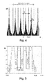
- FIG. 5 shows the frequency spectrum of the insonification waves emitted at a given instant by the sectorized emission means of the frontal sonar according to the invention
- FIG. 6A shows the transfer function between emission and reception when an insonified sector is angularly aligned with an image lobe of the lacunar antenna of FIG. 4 ;
- FIG. 6B shows the transfer function when the insonified sector is angularly offset relative to the image lobe of the lacunar antenna
- FIG. 7 shows the contrast function of the frontal sonar according to the invention.
- FIG. 1 schematically shows the context in which the frontal sonar according to the invention finds its most preferable use.
- FIG. 1A is a side view while FIG. 1B is a top view.
- a carrier 1 self-propelled or towed, is submerged so as to be positioned at an altitude H of about 30 m relative to seafloor 2 .
- Carrier 1 moves substantially along a navigation trajectory parallel to longitudinal axis X thereof.
- the direction perpendicular to both direction X and direction H is a lateral direction Y.
- Two lateral sonars (not shown) arranged on each of the flanks 1 a and 1 b of carrier 1 enable a progressive observation of the lateral areas, 2 a and 2 b respectively, during the displacement of the carrier.
- the matter is to map a seafloor strip located under the carrier and which, when the latter is at an altitude of 30 m relative to the floor, corresponds to a strip having a width W of about 45 m.
- Carrier 1 is provided with a sonar 10 arranged in front of it.
- the goal of frontal sonar 10 is to emit a sound wave able to “light” an insonified area E of seafloor 2 , and to “listen to” an imaged area I included in insonified area E.
- acquisition of a succession of imaged areas enables gradual image reconstruction of the central strip not observed by the lateral sonars.
- Constraints on the antenna are the following.
- the reasonable maximal span of the antenna arranged along lateral direction Y is 0.7 m. Taking into account the steric hindrance of acquisition electronics, the number of channels available for the reception is of the order of 48.
- the working frequency has to be lower than 600 kHz because, beyond this maximal frequency, the effects of signal absorption by the body of water become too large.
- FIG. 2 shows a numerical simulation giving the lateral and longitudinal resolutions for the field to be observed, at a working frequency f.
- the black curves join the points having the same lateral resolution and the white curves join the points having the same longitudinal resolution.
- the working frequency parameter By varying the working frequency parameter from a simulation to another, it is possible to select the frequency that offers the best average lateral resolution in the imaged area I.
- the longitudinal resolution does not depend on the antenna geometrical characteristics. So, the optimal working frequency is chosen to be 600 kHz, the area to be imaged being located at a range of 80 m. Accordingly, the reached resolution taking into account the constraints of the system is lower than 50 cm.
- the lateral resolution actually reached by an experimental frontal sonar made up according to the described embodiment is of 40 cm at a range of 80 m, with a working frequency of 400 kHz.
- the different transducers are arranged in line along lateral direction Y so as to form a periodic array.
- the receivers are separated with a pitch d in direction Y.
- This lacunar antenna 11 enables to observe a source M under an angle ⁇ in the plane XY. It is considered that the wave emitted by source M is a plane incident wave at antenna 11 . Acoustic signals respectively received by each of the transducers are thus identical, to within a temporal phase shift. The matter is then, acting on coefficients ⁇ 1 to ⁇ K , to correct this phase shift to reconstruct the incident plane wave.
- phase shift is known modulo ⁇ .
- source M may be located at different angular positions of the field observed. There is thus an ambiguity about the value of angle ⁇ under which an echo coming from source M is “viewed” by lacunar antenna 11 .
- homogeneously insonifying imaged area I gives the graph of FIG. 4 illustrating the gain of lacunar antenna 11 relative to observation angle ⁇ .
- a gain periodicity of ⁇ L 16.9° is recorded. Each period corresponds to an image lobe of antenna 11 .
- a sectorized insonification is performed.
- the insonification means according to the invention comprise as many emission channels as there are sectors to be insonified.
- the sonar according to the invention comprises four emission channels consisting of a transducer operating in emission and electronics for operating this emitter.
- the emitters used are directional, i.e. they emit in an emission cone of angle ⁇ e chosen so as to insonify a single sector of the seafloor (the angular aperture of which corresponds to the area to be imaged, divided by the number of emission sectors).
- sectors E 1 -E 4 are insonified at the same instant but by sound signals having different characteristic frequencies.
- the sectors are insonified successively in time by a sound signal of a given frequency.
- the temporal correlation between the echo receiving instant and the emission instant enables once again to associate the echo with a sector, thus with a particular image lobe, i.e. an interval of values of observation angle ⁇ , and then to remove ambiguity of antenna 11 .
- these two types of sectorized emission can be combined: for example, by performing a synchronised insonification at different frequencies in a first sonar operation recurrence, and a not-synchronized insonification at a given frequency in the next recurrence.
- FIG. 5 shows a frequency spectrum of the acoustic signals emitted respectively by the four sonar emission channels. This spectrum shows the superposition of four signals respectively centred on average frequencies f 1 , f 2 , f 3 and f 4 .
- each signal emitted by an emission transducer is a function called “FP code”, weighted by a Hanning function, so that, during the insonification of a sector at an average frequency f i , the signal component of frequency f j is insignificant. Interferences between image lobe i and image lobe j are thus prevented.
- FIG. 6A shows the ambiguity function when the insonified sector is angularly aligned with the image lobe of the antenna. It is noticed that the residual signals in the neighbouring lobes of the considered lobe have very small amplitude. Ambiguity of the antenna has thus been removed.
- Contrast is the ratio of the signal received from a shadow area on the main lobe (namely, the noise alone) to the contribution of the other interfering lobes (secondary lobes in emission, array lobe in reception). Concerning these questions on the notion of contrast, reference will be made to the book “Sonars et acoustique sous-marine”, Jean-Paul Marage, edited by Thomson-Sintra.
- the contrast optimization parameter is inter-sensor pitch d because the latter defines the angular spacing between two successive lobes.
- the criterion retained to optimize contrast of the sonar according to the invention is an inter-sensor pitch d that enables an emission/reception level at maximal misalignment equal to the amplitude of a conventional secondary lobe in emission.
- FIG. 7 shows the four contrast functions on the four useful lobes.
- the frontal sonar according to the invention can be used for the antenna synthesis, coherent or not coherent.
- the matter is to correlate the K transducer signals over a plurality of sonar operation recurrences.
Landscapes
- Engineering & Computer Science (AREA)
- Radar, Positioning & Navigation (AREA)
- Remote Sensing (AREA)
- Physics & Mathematics (AREA)
- Computer Networks & Wireless Communication (AREA)
- General Physics & Mathematics (AREA)
- Acoustics & Sound (AREA)
- Measurement Of Velocity Or Position Using Acoustic Or Ultrasonic Waves (AREA)
Applications Claiming Priority (3)
| Application Number | Priority Date | Filing Date | Title |
|---|---|---|---|
| FR0651763A FR2901365B1 (fr) | 2006-05-16 | 2006-05-16 | Sonar frontal ameliore |
| FR0651763 | 2006-05-16 | ||
| PCT/FR2007/051273 WO2007132125A2 (fr) | 2006-05-16 | 2007-05-15 | Sonar frontal ameliore |
Publications (2)
| Publication Number | Publication Date |
|---|---|
| US20090231957A1 US20090231957A1 (en) | 2009-09-17 |
| US8077549B2 true US8077549B2 (en) | 2011-12-13 |
Family
ID=37726990
Family Applications (1)
| Application Number | Title | Priority Date | Filing Date |
|---|---|---|---|
| US12/301,092 Active 2028-05-05 US8077549B2 (en) | 2006-05-16 | 2007-05-15 | Frontal sonar |
Country Status (7)
| Country | Link |
|---|---|
| US (1) | US8077549B2 (de) |
| EP (1) | EP2018579B1 (de) |
| JP (1) | JP5368974B2 (de) |
| CA (1) | CA2652564A1 (de) |
| FR (1) | FR2901365B1 (de) |
| NO (1) | NO20085117L (de) |
| WO (1) | WO2007132125A2 (de) |
Cited By (1)
| Publication number | Priority date | Publication date | Assignee | Title |
|---|---|---|---|---|
| US20130182530A1 (en) * | 2010-09-30 | 2013-07-18 | Advantest Corporation | Converter and measuring apparatus |
Families Citing this family (5)
| Publication number | Priority date | Publication date | Assignee | Title |
|---|---|---|---|---|
| FR2901365B1 (fr) * | 2006-05-16 | 2008-08-22 | Ixsea Soc Par Actions Simplifi | Sonar frontal ameliore |
| JP5148353B2 (ja) * | 2008-04-25 | 2013-02-20 | 三菱重工業株式会社 | 水中航走体および障害物探知装置 |
| EP4024079A1 (de) * | 2013-02-13 | 2022-07-06 | Farsounder, Inc. | Integrierte sonarvorrichtungen |
| WO2018104854A1 (en) * | 2016-12-05 | 2018-06-14 | Poynting Antennas (Pty) Limited | Mimo system and method utilizing interferometric pattern |
| KR102078590B1 (ko) * | 2018-07-18 | 2020-02-19 | 국방과학연구소 | 수중 근접 장애물 고속 탐지를 위한 다중 주파수 스캐닝 소나 |
Citations (7)
| Publication number | Priority date | Publication date | Assignee | Title |
|---|---|---|---|---|
| US4970700A (en) | 1989-11-20 | 1990-11-13 | Westinghouse Electric Corp. | Sonar apparatus |
| US5177710A (en) | 1992-01-31 | 1993-01-05 | Westinghouse Electric Corp. | High speed multibeam sidelock sonar with few elements |
| EP0568427A1 (de) | 1992-04-30 | 1993-11-03 | Thomson-Csf | Verfahren und Vorrichtung zur Detektion von einem oder mehreren Objekten in einem Winkelsektor, mit Anwendungen |
| US5412618A (en) * | 1994-04-07 | 1995-05-02 | Westinghouse Electric Corporation | Spotlight-mode synthetic aperture side-look sonar |
| US5596549A (en) | 1995-07-06 | 1997-01-21 | Northrop Grumman Corporation | Side look sonar apparatus and method |
| US20050099887A1 (en) | 2002-10-21 | 2005-05-12 | Farsounder, Inc | 3-D forward looking sonar with fixed frame of reference for navigation |
| WO2007132125A2 (fr) * | 2006-05-16 | 2007-11-22 | Ixsea | Sonar frontal ameliore |
Family Cites Families (2)
| Publication number | Priority date | Publication date | Assignee | Title |
|---|---|---|---|---|
| JPS61277077A (ja) * | 1985-05-31 | 1986-12-08 | Furuno Electric Co Ltd | 水中探知装置 |
| US5200931A (en) * | 1991-06-18 | 1993-04-06 | Alliant Techsystems Inc. | Volumetric and terrain imaging sonar |
-
2006
- 2006-05-16 FR FR0651763A patent/FR2901365B1/fr active Active
-
2007
- 2007-05-15 US US12/301,092 patent/US8077549B2/en active Active
- 2007-05-15 WO PCT/FR2007/051273 patent/WO2007132125A2/fr not_active Ceased
- 2007-05-15 JP JP2009510513A patent/JP5368974B2/ja active Active
- 2007-05-15 CA CA002652564A patent/CA2652564A1/fr not_active Abandoned
- 2007-05-15 EP EP07766048.8A patent/EP2018579B1/de active Active
-
2008
- 2008-12-09 NO NO20085117A patent/NO20085117L/no not_active Application Discontinuation
Patent Citations (10)
| Publication number | Priority date | Publication date | Assignee | Title |
|---|---|---|---|---|
| US4970700A (en) | 1989-11-20 | 1990-11-13 | Westinghouse Electric Corp. | Sonar apparatus |
| US5177710A (en) | 1992-01-31 | 1993-01-05 | Westinghouse Electric Corp. | High speed multibeam sidelock sonar with few elements |
| FR2688894A1 (fr) | 1992-01-31 | 1993-09-24 | Westinghouse Electric Corp | Sonar lateral rapide a faisceaux multiples comportant peu d'elements et procede pour sa mise en óoeuvre. |
| EP0568427A1 (de) | 1992-04-30 | 1993-11-03 | Thomson-Csf | Verfahren und Vorrichtung zur Detektion von einem oder mehreren Objekten in einem Winkelsektor, mit Anwendungen |
| US5598163A (en) | 1992-04-30 | 1997-01-28 | Thomson-Csf | Method and system for object detection within an angular zone, and its applications |
| US5412618A (en) * | 1994-04-07 | 1995-05-02 | Westinghouse Electric Corporation | Spotlight-mode synthetic aperture side-look sonar |
| US5596549A (en) | 1995-07-06 | 1997-01-21 | Northrop Grumman Corporation | Side look sonar apparatus and method |
| US20050099887A1 (en) | 2002-10-21 | 2005-05-12 | Farsounder, Inc | 3-D forward looking sonar with fixed frame of reference for navigation |
| WO2007132125A2 (fr) * | 2006-05-16 | 2007-11-22 | Ixsea | Sonar frontal ameliore |
| US20090231957A1 (en) * | 2006-05-16 | 2009-09-17 | Ixsea | Frontal sonar |
Non-Patent Citations (1)
| Title |
|---|
| International Search Report dated Nov. 7, 2007, from corresponding PCT application. |
Cited By (2)
| Publication number | Priority date | Publication date | Assignee | Title |
|---|---|---|---|---|
| US20130182530A1 (en) * | 2010-09-30 | 2013-07-18 | Advantest Corporation | Converter and measuring apparatus |
| US8711657B2 (en) * | 2010-09-30 | 2014-04-29 | Advantest Corporation | Converter and measuring apparatus |
Also Published As
| Publication number | Publication date |
|---|---|
| EP2018579A2 (de) | 2009-01-28 |
| NO20085117L (no) | 2009-01-29 |
| US20090231957A1 (en) | 2009-09-17 |
| WO2007132125A3 (fr) | 2008-01-17 |
| JP5368974B2 (ja) | 2013-12-18 |
| EP2018579B1 (de) | 2016-05-18 |
| FR2901365A1 (fr) | 2007-11-23 |
| CA2652564A1 (fr) | 2007-11-22 |
| JP2009537809A (ja) | 2009-10-29 |
| FR2901365B1 (fr) | 2008-08-22 |
| WO2007132125A2 (fr) | 2007-11-22 |
Similar Documents
| Publication | Publication Date | Title |
|---|---|---|
| US8077549B2 (en) | Frontal sonar | |
| US7722541B2 (en) | Multiple receive beams for rapid acquisition | |
| US10605914B2 (en) | Sonar data compression | |
| US20100217124A1 (en) | Ultrasound imaging system and method using multiline acquisition with high frame rate | |
| US12392894B2 (en) | Multimission and multispectral sonar | |
| GB2099582A (en) | Ultrasonic image methods and apparatus | |
| DE2439231C2 (de) | Sonargerät | |
| JPH11221215A (ja) | 超音波イメージング・システムおよびそのトランスジューサ・アレイの作動方法 | |
| US5033029A (en) | Interlaced sonar system | |
| US5177710A (en) | High speed multibeam sidelock sonar with few elements | |
| GB2489072A (en) | A transmit/receive array arranged for the suppression of sidelobes | |
| CN1476539A (zh) | 用于获得图像的方法、系统和探测器 | |
| US20060239119A1 (en) | Multiple projectors for increased resolution receive beam processing of echoing sonars and radars | |
| Kortbek et al. | P2b-1 synthetic aperture focusing applied to imaging using a rotating single element transducer | |
| Tonard et al. | Towards development of autofocusing schemes for phase compensation of synthetic aperture sonars | |
| Hayes et al. | Test results from a multi-frequency bathymetric synthetic aperture sonar | |
| JP3006917B2 (ja) | 高分解能計測方法および装置 | |
| Sara | Next generation buried object scanning sonar (BOSS) for detecting buried UXO in shallow water | |
| Alais et al. | Noncoherent synthetic aperture Imaging | |
| Elminowicz et al. | High resolution multi-beam side looking sonar | |
| Alais et al. | A high resolution Sidescan Sonar | |
| Liu et al. | High-Resolution Sonar Imaging Using Sparse Transmitting and Dense Receiving Arrays | |
| Alais et al. | A multi-look front-scan sonar system. First imaging results | |
| Alais et al. | A new generation side scan sonar | |
| Pinto | AquaPix: a family of software-defined synthetic aperture sonars |
Legal Events
| Date | Code | Title | Description |
|---|---|---|---|
| AS | Assignment |
Owner name: IXSEA, FRANCE Free format text: ASSIGNMENT OF ASSIGNORS INTEREST;ASSIGNORS:JEAN, FREDERIC;MOSCA, FREDERIC;REEL/FRAME:022578/0947;SIGNING DATES FROM 20081128 TO 20081201 Owner name: IXSEA, FRANCE Free format text: ASSIGNMENT OF ASSIGNORS INTEREST;ASSIGNORS:JEAN, FREDERIC;MOSCA, FREDERIC;SIGNING DATES FROM 20081128 TO 20081201;REEL/FRAME:022578/0947 |
|
| AS | Assignment |
Owner name: IXBLUE, FRANCE Free format text: CHANGE OF NAME;ASSIGNOR:IXSEA;REEL/FRAME:026322/0084 Effective date: 20101102 |
|
| STCF | Information on status: patent grant |
Free format text: PATENTED CASE |
|
| FPAY | Fee payment |
Year of fee payment: 4 |
|
| MAFP | Maintenance fee payment |
Free format text: PAYMENT OF MAINTENANCE FEE, 8TH YEAR, LARGE ENTITY (ORIGINAL EVENT CODE: M1552); ENTITY STATUS OF PATENT OWNER: LARGE ENTITY Year of fee payment: 8 |
|
| MAFP | Maintenance fee payment |
Free format text: PAYMENT OF MAINTENANCE FEE, 12TH YEAR, LARGE ENTITY (ORIGINAL EVENT CODE: M1553); ENTITY STATUS OF PATENT OWNER: LARGE ENTITY Year of fee payment: 12 |
|
| AS | Assignment |
Owner name: EXAIL, FRANCE Free format text: CHANGE OF NAME AND ADDRESS;ASSIGNOR:IXBLUE;REEL/FRAME:063237/0952 Effective date: 20230101 |