US8070430B2 - Resinous shroud and manufacturing method of the same - Google Patents
Resinous shroud and manufacturing method of the same Download PDFInfo
- Publication number
- US8070430B2 US8070430B2 US12/313,727 US31372708A US8070430B2 US 8070430 B2 US8070430 B2 US 8070430B2 US 31372708 A US31372708 A US 31372708A US 8070430 B2 US8070430 B2 US 8070430B2
- Authority
- US
- United States
- Prior art keywords
- resinous
- casing
- retaining
- shroud
- ring
- Prior art date
- Legal status (The legal status is an assumption and is not a legal conclusion. Google has not performed a legal analysis and makes no representation as to the accuracy of the status listed.)
- Expired - Fee Related, expires
Links
- 238000004519 manufacturing process Methods 0.000 title description 4
- 239000011347 resin Substances 0.000 claims abstract description 49
- 229920005989 resin Polymers 0.000 claims abstract description 49
- 239000000463 material Substances 0.000 claims abstract description 42
- 238000000465 moulding Methods 0.000 claims description 19
- 230000000052 comparative effect Effects 0.000 description 2
- 238000001816 cooling Methods 0.000 description 2
- 239000000428 dust Substances 0.000 description 2
- 238000000034 method Methods 0.000 description 2
- 238000007789 sealing Methods 0.000 description 2
- 239000004743 Polypropylene Substances 0.000 description 1
- 238000007664 blowing Methods 0.000 description 1
- 238000010276 construction Methods 0.000 description 1
- 230000000694 effects Effects 0.000 description 1
- 239000012467 final product Substances 0.000 description 1
- 239000003365 glass fiber Substances 0.000 description 1
- 238000001746 injection moulding Methods 0.000 description 1
- 230000004048 modification Effects 0.000 description 1
- 238000012986 modification Methods 0.000 description 1
- 230000002093 peripheral effect Effects 0.000 description 1
- -1 polypropylene Polymers 0.000 description 1
- 229920001155 polypropylene Polymers 0.000 description 1
- 239000000047 product Substances 0.000 description 1
- 239000007787 solid Substances 0.000 description 1
Images


Classifications
-
- F—MECHANICAL ENGINEERING; LIGHTING; HEATING; WEAPONS; BLASTING
- F04—POSITIVE - DISPLACEMENT MACHINES FOR LIQUIDS; PUMPS FOR LIQUIDS OR ELASTIC FLUIDS
- F04D—NON-POSITIVE-DISPLACEMENT PUMPS
- F04D29/00—Details, component parts, or accessories
- F04D29/40—Casings; Connections of working fluid
- F04D29/52—Casings; Connections of working fluid for axial pumps
- F04D29/522—Casings; Connections of working fluid for axial pumps especially adapted for elastic fluid pumps
- F04D29/526—Details of the casing section radially opposing blade tips
-
- B—PERFORMING OPERATIONS; TRANSPORTING
- B29—WORKING OF PLASTICS; WORKING OF SUBSTANCES IN A PLASTIC STATE IN GENERAL
- B29C—SHAPING OR JOINING OF PLASTICS; SHAPING OF MATERIAL IN A PLASTIC STATE, NOT OTHERWISE PROVIDED FOR; AFTER-TREATMENT OF THE SHAPED PRODUCTS, e.g. REPAIRING
- B29C45/00—Injection moulding, i.e. forcing the required volume of moulding material through a nozzle into a closed mould; Apparatus therefor
- B29C45/0025—Preventing defects on the moulded article, e.g. weld lines, shrinkage marks
-
- F—MECHANICAL ENGINEERING; LIGHTING; HEATING; WEAPONS; BLASTING
- F04—POSITIVE - DISPLACEMENT MACHINES FOR LIQUIDS; PUMPS FOR LIQUIDS OR ELASTIC FLUIDS
- F04D—NON-POSITIVE-DISPLACEMENT PUMPS
- F04D29/00—Details, component parts, or accessories
- F04D29/02—Selection of particular materials
- F04D29/023—Selection of particular materials especially adapted for elastic fluid pumps
-
- F—MECHANICAL ENGINEERING; LIGHTING; HEATING; WEAPONS; BLASTING
- F04—POSITIVE - DISPLACEMENT MACHINES FOR LIQUIDS; PUMPS FOR LIQUIDS OR ELASTIC FLUIDS
- F04D—NON-POSITIVE-DISPLACEMENT PUMPS
- F04D29/00—Details, component parts, or accessories
- F04D29/60—Mounting; Assembling; Disassembling
- F04D29/601—Mounting; Assembling; Disassembling specially adapted for elastic fluid pumps
-
- B—PERFORMING OPERATIONS; TRANSPORTING
- B29—WORKING OF PLASTICS; WORKING OF SUBSTANCES IN A PLASTIC STATE IN GENERAL
- B29C—SHAPING OR JOINING OF PLASTICS; SHAPING OF MATERIAL IN A PLASTIC STATE, NOT OTHERWISE PROVIDED FOR; AFTER-TREATMENT OF THE SHAPED PRODUCTS, e.g. REPAIRING
- B29C45/00—Injection moulding, i.e. forcing the required volume of moulding material through a nozzle into a closed mould; Apparatus therefor
- B29C45/0025—Preventing defects on the moulded article, e.g. weld lines, shrinkage marks
- B29C2045/0027—Gate or gate mark locations
-
- B—PERFORMING OPERATIONS; TRANSPORTING
- B29—WORKING OF PLASTICS; WORKING OF SUBSTANCES IN A PLASTIC STATE IN GENERAL
- B29C—SHAPING OR JOINING OF PLASTICS; SHAPING OF MATERIAL IN A PLASTIC STATE, NOT OTHERWISE PROVIDED FOR; AFTER-TREATMENT OF THE SHAPED PRODUCTS, e.g. REPAIRING
- B29C45/00—Injection moulding, i.e. forcing the required volume of moulding material through a nozzle into a closed mould; Apparatus therefor
- B29C45/0046—Details relating to the filling pattern or flow paths or flow characteristics of moulding material in the mould cavity
-
- F—MECHANICAL ENGINEERING; LIGHTING; HEATING; WEAPONS; BLASTING
- F01—MACHINES OR ENGINES IN GENERAL; ENGINE PLANTS IN GENERAL; STEAM ENGINES
- F01P—COOLING OF MACHINES OR ENGINES IN GENERAL; COOLING OF INTERNAL-COMBUSTION ENGINES
- F01P5/00—Pumping cooling-air or liquid coolants
- F01P5/02—Pumping cooling-air; Arrangements of cooling-air pumps, e.g. fans or blowers
- F01P5/06—Guiding or ducting air to, or from, ducted fans
-
- F—MECHANICAL ENGINEERING; LIGHTING; HEATING; WEAPONS; BLASTING
- F05—INDEXING SCHEMES RELATING TO ENGINES OR PUMPS IN VARIOUS SUBCLASSES OF CLASSES F01-F04
- F05D—INDEXING SCHEME FOR ASPECTS RELATING TO NON-POSITIVE-DISPLACEMENT MACHINES OR ENGINES, GAS-TURBINES OR JET-PROPULSION PLANTS
- F05D2230/00—Manufacture
- F05D2230/50—Building or constructing in particular ways
- F05D2230/53—Building or constructing in particular ways by integrally manufacturing a component, e.g. by milling from a billet or one piece construction
-
- F—MECHANICAL ENGINEERING; LIGHTING; HEATING; WEAPONS; BLASTING
- F05—INDEXING SCHEMES RELATING TO ENGINES OR PUMPS IN VARIOUS SUBCLASSES OF CLASSES F01-F04
- F05D—INDEXING SCHEME FOR ASPECTS RELATING TO NON-POSITIVE-DISPLACEMENT MACHINES OR ENGINES, GAS-TURBINES OR JET-PROPULSION PLANTS
- F05D2300/00—Materials; Properties thereof
- F05D2300/40—Organic materials
- F05D2300/43—Synthetic polymers, e.g. plastics; Rubber
-
- Y—GENERAL TAGGING OF NEW TECHNOLOGICAL DEVELOPMENTS; GENERAL TAGGING OF CROSS-SECTIONAL TECHNOLOGIES SPANNING OVER SEVERAL SECTIONS OF THE IPC; TECHNICAL SUBJECTS COVERED BY FORMER USPC CROSS-REFERENCE ART COLLECTIONS [XRACs] AND DIGESTS
- Y10—TECHNICAL SUBJECTS COVERED BY FORMER USPC
- Y10T—TECHNICAL SUBJECTS COVERED BY FORMER US CLASSIFICATION
- Y10T29/00—Metal working
- Y10T29/49—Method of mechanical manufacture
- Y10T29/49229—Prime mover or fluid pump making
- Y10T29/49236—Fluid pump or compressor making
- Y10T29/49245—Vane type or other rotary, e.g., fan
Definitions
- the present invention relates to a resinous shroud for a fan and an air cleaner, and a method of manufacturing a resinous shroud.
- a casing used as a container of an air cleaner and a shroud ring portion for holding a fan are integrally formed to be adjacent each other.
- a gate portion for filling the resin material is disposed at a center portion of the shroud ring portion and at a predetermined end portion of the air cleaner casing.
- the resin material flowing to a molding die of the casing from the center portion of the shroud ring portion joins windingly the resin material flowing in the molding die of the casing in one direction so that welds generate at a junction.
- deformation such as cambers generates in the casing after the shroud was formed.
- the casing is difficult to be fitted to an air cleaner element and/or a cover member, and thereby it becomes difficult for an appropriate assembling and a sealing to be performed.
- a resinous shroud for a fan and an air cleaner includes a retaining portion for retaining a driving portion for driving the fan; a plurality of stay portions extended from the retaining portion radially outside; a ring portion configured to hold the fan, the ring portion being connected to an end portion of the plurality of stay portions extended from the retaining portion; an air intake portion expanded from an outer periphery of the ring portion; a casing configured to hold therein a filter element of the air cleaner; and a resinous wall portion extending from the retaining portion to the ring portion.
- the casing is adjacent to the ring portion and integrated with the air intake portion.
- the retaining portion is molded from a resin material filled by using a first gate portion positioned at a portion corresponding to a center portion of the retaining portion.
- the casing is molded from the resin material filled by using a second gate portion positioned at a portion corresponding to an end portion of the casing.
- the resinous wall portion and a part of the plurality of stay portions are formed by the resin material flowing from the first gate portion to a portion corresponding to the casing in a resin molding.
- the welds generated at the casing can be made small, and the cambers generated at the casing can be suppressed.
- a resinous shroud for a fan and an air cleaner includes a retaining portion for retaining a driving portion for driving the fan; a ring portion configured to hold the fan; a plurality of connection portions for connecting the ring portion and the retaining portion; an air intake portion expanded from an outer periphery of the ring portion; and a casing configured to hold therein a filter element of the air cleaner.
- the plurality of connection portions is extended from the retaining portion radially outside to the ring portion.
- the casing is adjacent to the ring portion and integrated with the air intake portion.
- the number of the plurality of connection portions included in a range of plus or minus 60 degrees with respect to a reference line (A-A) as a center line is three or more on a plane parallel to the ring portion including the reference line (A-A), the reference line (A-A) being defined by connecting the center portion of the retaining portion and the casing in a shortest path.
- the welds generated at the casing can be made small, and the cambers generated at the casing can be suppressed.
- a method for manufacturing a resinous shroud including a shroud portion and a casing includes injecting a resin material into a molding die from a first gate portion and a second gate portion of the molding die; forming a plurality of stay portions and a resinous wall portion of the shroud portion by extending the resin material injected from the first gate portion radially outside from the first gate portion, and forming the casing by flowing the resin material injected from the second gate portion toward a portion corresponding to a second surface of the casing.
- the first gate portion is positioned at a portion corresponding to a center portion of a retaining portion of the shroud portion and the second gate portion is positioned at a portion corresponding to a first surface of the casing.
- the second surface is opposite from the first surface.
- the welds generated at the casing can be made small, and the cambers generated at the casing can be suppressed.
- FIG. 1 is a front view showing a casing-integrated shroud according to a first embodiment of the present invention
- FIG. 2 is a cross sectional view showing the casing-integrated shroud, taken along line II-II in FIG. 1 ;
- FIG. 3 is a perspective view showing a resinous wall portion in FIG. 1 ;
- FIG. 4 is a cross sectional view showing an extended resinous wall portion of a casing-integrated shroud according to a second embodiment of the present invention.
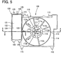
- FIG. 5 is front view showing a casing-integrated shroud according to a modified example of the present invention.
- a casing-integrated shroud 100 made of resin (hereinafter referred to as a shroud) of the first embodiment is used for an electrical blower mounted to a radiator (not shown in drawings) of a vehicle engine.
- the electrical blower is provided such that an electrical motor (a driving portion), which is not shown in drawings, is attached to a motor retaining portion 111 of the shroud 100 , and further, a fan 200 for blowing air (shown in FIG. 2 ) is attached to a shaft of the electrical motor. Attaching portions 115 are disposed at four corners of an air intake portion 114 , for example.
- the electrical blower is fixed at the engine side of the radiator by using the attaching portions 115 , and is located to blow air for cooling to a core portion of the radiator.
- the electrical blower is a suction type electrical fan for drawing air to be blown toward the engine from a grille of the vehicle, that is, toward the fan 200 from the core portion of the radiator.
- the shroud 100 in the electrical fan includes a shroud portion 110 and a casing 120 .
- the shroud 100 is made of polypropylene material including 25% to 30% fibrous glass, for example.
- the shroud portion 110 and the casing 120 are integrally formed by injection molding.
- the motor retaining portion 111 which has approximately a ring shape, is formed at a center portion of the shroud portion 110 to retain and support the electrical motor.
- multiple holes 111 a for attaching are provided circumferentially, such that screws for fixing the electrical motor are inserted.
- a center portion of the motor retaining portion 111 corresponds to a position of a gate portion 116 for filling a resin material when the shroud portion 110 is resin-molded.
- the gate portion 116 is located at a radial inside of the motor retaining portion 111 , and multiple runners (e.g., three runners shown by a two-dotted chain line in FIG. 1 ) of the gate portion 116 extend radially outside.
- the multiple runners of the gate portion 116 can be located equiangularly in a circumferentially direction.
- the resin material can be filled from a portion corresponding to the center portion of the shroud portion 110 to an entire circumference of the air intake portion 114 .
- the gate portion 116 is located in a molding die for molding the shroud 100 .
- the runners of the gate portion 116 are removed afterward, and prints of the gate are remained at multiple portions of the radial inside of the motor retaining portion 111 in the shroud portion 110 after the resin molding.
- motor stay portions 112 a to 112 f are extended from an outer diameter side (outer peripheral side) of the motor retaining portion 111 radially outside.
- the end portions of the motor stay portions 112 a to 112 f are connected to one end portion of a ring portion 113 on an opening side in an axial direction.
- the motor stay portions 112 a to 112 f are used as support members for supporting the motor retaining portion 111 strongly.
- the motor stay portions 112 a to 112 f have a U-shape in a cross section perpendicular to the longitudinal direction, which is vertically long and has a narrow width, for example.
- the motor stay portions 112 a and 112 b among the motor stay portions 112 a to 112 f are disposed to extend toward the casing 120 described below.
- the ring portion 113 is a ring-shaped member having a flat and cylindrical space in which the fan 200 is accommodated.
- the air intake portion 114 which is expanded like a smooth skirt, is formed from other end portion opposite from the one end portion of the opening side, toward the core portion of the radiator such that an outer shape of the air intake portion 114 becomes approximately a rectangular shape at the core portion of the radiator.
- the air drawn by the fan 200 is fed from the core portion of the radiator to the fan 200 via the air intake portion 114 .
- the casing 120 is a semi-container body such as a box-shaped body having a vertically long rectangular parallelepiped including an opening 121 at one side, and disposed adjacent to a side of the ring portion 113 (a left side in FIG. 1 ).
- the opening 121 opens toward a downstream side (a front side of a paper in FIG. 1 ) of the air blown by the fan 200 .
- a flange portion 122 projected along the one side (a virtual surface) of the opening 121 is formed on an outer periphery of the opening 121 .
- a projecting portion 122 a for sealing, which is projected slightly from the flange portion 122 is formed on the flange portion 122 as shown in FIG. 2 .
- the casing 120 has a side wall 123 adjacent to the ring portion 113 , and a side wall 124 opposite to the side wall 123 .
- a circular suction opening 124 a is formed at a lower side in the side wall 124 of the casing 120 , and an outside and an inside of the casing 120 communicate with each other via the circular suction opening 124 a .
- Rectangular plate-like connection portions 125 are provided to be connected with cover member (cap portion) for closing the opening 121 , which are not shown in drawings.
- the connection portions 125 are formed to be projected approximately at four corners of the flange portion 122 .
- a bottom wall, which is opposite from the opening 121 , of the casing 120 is connected to the air intake portion 114 .
- Upper center portion of the flange portion 122 of the casing 120 corresponds to an arrangement position of a gate portion 126 for filling the resin material when molding the casing 120 .
- the resin material is filled and jetted toward the lower side of the casing 120 from the gate portion 126 .
- the gate portion 126 is located at the arrangement position in the molding die for forming the shroud 100 , and prints of the gate are remained at the upper center portion of the casing 120 after the resin molding.
- a filter element for collecting and removing dust and the cover member (cap portion) for closing the opening 121 are assembled and connected to the casing 120 so that an air cleaner is formed. That is, an outer periphery of the filter element is disposed to be along a surface of the flange portion 122 , and the cap portion, which is a semi-container body similar to the casing 120 , is connected to the connection portions 125 of the casing 120 while the outer periphery of the filter element is interposed between the cap portion and the casing 120 .
- a discharge opening is formed at an upper portion of the cap portion so that air after passing through the filter element is discharged from the discharge opening.
- a suction duct which opens in the vicinity of the grille of the vehicle, is connected to the suction opening 124 a of the casing 120 , and an intake air duct, which is connected to an air intake side of the engine, is connected to the discharge opening.
- the air intake side becomes a negative pressure, and external air (air) is drawn into the casing 120 from the suction duct. Then, dust in the air is removed when the air passes through the filter element, and the filtered air flows into the cap portion and supplied to the air intake side of the engine from the discharge opening.
- two resinous wall portions 131 are formed as connection portions connected between the motor retaining portion 111 in the shroud portion 110 and the casing 120 .
- Each of the resinous wall portions 131 is a round bar-shaped member having a circular cross-sectional shape.
- Each of the two resinous wall portions 131 is extended to the casing 120 from the motor retaining portion 111 at a vicinity of the base portions of the motor stay portions 112 a and 112 b .
- the resinous wall portions 131 extending from the motor retaining portion 111 are connected to the ring portion 113 and the side wall 123 .
- Connection points of the resinous wall portions 131 with the ring portion 113 are set at positions to be substantially equal distance between a connection point of the motor stay portion 112 a to the adjacent ring portion 113 and a connection point of the motor stay portion 112 b to the adjacent ring portion 113 in the circumferential direction. That is, the resinous wall portions 131 are separated from the adjacent motor stay portions 112 a and 112 b by an approximately equal distance in the circumferential direction.
- the resinous wall portions 131 are members different from the supporting members such as the motor stay portions 112 a to 112 f for supporting the motor retaining portion 111 strongly. That is, the resinous wall portions 131 are formed to absorb an excess resin material so as to accurately form the shroud 100 . Therefore, the resinous wall portions 131 are formed additionally and generally not used as a supporting member for supporting the fan 200 .
- the resinous wall portions 131 are formed by runner portions, through which the resin material passes while the shroud 100 is molded, and remained as rod-shaped resinous wall portion after the shroud 100 is molded. With respect to the shape of the resinous wall portion 131 , different configuration may be taken.
- the cross-sectional shape is not limited to the circular, and an elongated shape, an ellipsoidal shape, and a streamline wing shape may be used.
- size of the resinous wall portion and the number of the resinous wall portion may be selected arbitrary.
- the shroud 100 is molded by using a resin material as described below.
- the molten resin material is injected into the gate portions 116 and 126 with the molding die closed (an outline arrow A 1 in FIG. 1 ).
- the resin material injected from the gate portion 116 flows to extend radially outside from a portion corresponding to the center portion of the shroud portion 110 . That is, the resin material flows from a portion corresponding to the motor retaining portion 111 and passes through the portions corresponding to the motor stay portions 112 a to 112 f . Then, the resin material is filled in portions corresponding to the ring portion 113 and the air intake portion 114 so that the shroud portion 110 is formed.
- the resin material injected from the gate portion 126 flows in a molding die toward a portion corresponding to the lower side of the casing 120 from a portion corresponding to the upper center portion of the casing 120 so that the casing 120 is formed integrally with the air intake portion 114 .
- the molding die is opened and the molded shroud 100 is taken out from the molding die. Then, unnecessary runner portions shown by the two-dotted chain line in FIG. 1 are removed so that a final product is obtained.
- the resin material flows into the portions corresponding to the casing 120 from the portion corresponding to the center side of the shroud portion 110 through the portions corresponding to the motor stay portions 112 a and 112 b as shown by solid arrows A 2 in FIG. 1 , and is joined with the resin material, which is filled for forming the casing 120 . Therefore, bulky welds may be generated at a substantially center position between the motor stay portion 112 a on the ring portion 113 and the motor stay portion 112 b on the ring portion 113 . Furthermore, bulky cambers, which make the casing 120 expand, may be generated at the side wall 123 of the casing 120 .
- the flows of the resin material are added as shown by dashed arrows A 3 in FIG. 1 so as to form the additional resinous wall portions 131 , and the resin material, which flows into a portion corresponding to the casing 120 from a portion corresponding to the center portion of the shroud portion 110 , can be dispersed to join the resin material, which is filled in a portion according to the casing 120 when the shroud 100 is molded. Therefore, the welds generated at the casing 120 can be made small, and the cambers generated at the casing 120 can be suppressed.
- the camber of 0.8 mm at a maximum is generated on the side wall.
- the size of the camber can be suppressed to be 0.35 mm at a maximum.
- a second embodiment of the present invention will be described with reference to FIG. 4 .
- an extended resinous wall portion 132 is formed in place of the resinous wall portions 131 .
- the extended resinous wall portion 132 is formed in order to extend a length of the flow of the resin material to the portion corresponding to the casing 120 from the gate portion 116 via the portions corresponding to the motor stay portions 112 a and 112 b when the shroud 100 is molded.
- the extended resinous wall portion 132 is disposed between the end portion of the motor stay portion 112 a and the end portion of the motor stay portion 112 b at the outer periphery side of the ring portion 113 .
- the extended resinous wall portion 132 is a ring-shaped member, which is connected to an end portion of an opposite portion from the motor stay portions of the ring portion 113 (an end portion of the air intake portion 114 side). That is, as shown in FIG.
- the ring portion 113 and the extended resinous wall portion 132 are configured to form approximately a vertically long U-shaped cross section by a double ring structure so that the motor stay portions 112 a and 112 b , the ring portion 113 and the extended resinous wall portion 132 are connected in this order.
- the end portion of the extended resinous wall portion 132 on a side of the motor stay portions 112 a , 112 b is connected to the flange portion 122 of the opening of the casing 120 .
- the shroud 100 when the shroud 100 is molded, the length of the flow of the resin material to the portion corresponding to the casing 120 from a portion corresponding to the center portion of the motor retaining portion 111 can be extended by the length of the extended resinous wall portion 132 .
- a quantity of the resin material flowing to the portion corresponding to the casing 120 from the center portion can be made small. Therefore, the welds generated at the casing 120 can be made small, and the cambers generated at the casing 120 can be suppressed.
- the extended resinous wall portion 132 is not limited to the ring-shaped resinous wall portion, and a rib-shaped resinous wall portion and a rod-shaped resinous wall portion may be used.
- the casing-integrated shroud 100 is applied to the electrical blower, in which the fan 200 is rotated by the electrical motor, it is not limited to the configuration.
- the casing-integrated shroud 100 may be applied to a hydraulic fan, in which the fan 200 is rotated by a hydraulic motor.
- connection portions i.e., the sum of the motor stay portions 112 a to 112 f and the resinous wall portion 131 ) included in a range of ⁇ 60° with respect to the line A-A as a center line is four on a plane parallel to the ring portion including the line A-A in the above-described embodiments.
- the number of the connection portions in the present invention is not limited to four.
- the number of the connection portions is three.
- the number of the connection portions may be three or more (for example, 3, 4, 5, 6 . . .
- connection portion may be formed in parallel to a connection line (see reference line A-A in FIG. 5 ) connecting the center portion of the retaining portion 111 and the casing 120 in the shortest path, or may be formed to be tilted with respect to the connection line.
Abstract
Description
Claims (9)
Applications Claiming Priority (2)
| Application Number | Priority Date | Filing Date | Title |
|---|---|---|---|
| JP2007316289A JP2009137171A (en) | 2007-12-06 | 2007-12-06 | Resin-made shroud |
| JP2007-316289 | 2007-12-06 |
Publications (2)
| Publication Number | Publication Date |
|---|---|
| US20090148281A1 US20090148281A1 (en) | 2009-06-11 |
| US8070430B2 true US8070430B2 (en) | 2011-12-06 |
Family
ID=40721858
Family Applications (1)
| Application Number | Title | Priority Date | Filing Date |
|---|---|---|---|
| US12/313,727 Expired - Fee Related US8070430B2 (en) | 2007-12-06 | 2008-11-24 | Resinous shroud and manufacturing method of the same |
Country Status (3)
| Country | Link |
|---|---|
| US (1) | US8070430B2 (en) |
| JP (1) | JP2009137171A (en) |
| DE (1) | DE102008059821A1 (en) |
Families Citing this family (1)
| Publication number | Priority date | Publication date | Assignee | Title |
|---|---|---|---|---|
| KR101528237B1 (en) * | 2012-08-31 | 2015-06-11 | 한라비스테온공조 주식회사 | Shroud |
Citations (10)
| Publication number | Priority date | Publication date | Assignee | Title |
|---|---|---|---|---|
| US5427502A (en) * | 1994-03-28 | 1995-06-27 | Deere & Company | Fan shroud aspirator |
| JPH1082319A (en) | 1996-09-09 | 1998-03-31 | Calsonic Corp | Radiator unit |
| JPH10238825A (en) | 1997-02-28 | 1998-09-08 | Yamaha Motor Co Ltd | Outdoor machine unit of engine driven heat pump |
| US20020150478A1 (en) * | 2001-04-11 | 2002-10-17 | Shinji Aoki | Vehicle blower unit |
| US20030094010A1 (en) * | 2001-11-22 | 2003-05-22 | Tosiharu Katatani | Single-package air conditioner |
| JP2005081611A (en) | 2003-09-05 | 2005-03-31 | Ricoh Co Ltd | Injection mold and resin molded product |
| US6938727B2 (en) * | 2002-06-03 | 2005-09-06 | Siemens Vdo Automotive Inc. | Integrated engine compartment component and air intake system |
| US7008180B2 (en) * | 2002-06-28 | 2006-03-07 | Seiko Epson Corporation | Axial-flow fan and projector provided with the same |
| US20060266309A1 (en) * | 2004-08-14 | 2006-11-30 | Deere & Company, A Delaware Corporation | Vehicle cooling system |
| JP2007327442A (en) | 2006-06-08 | 2007-12-20 | Denso Corp | Air intake device for internal combustion engine |
Family Cites Families (7)
| Publication number | Priority date | Publication date | Assignee | Title |
|---|---|---|---|---|
| JPH08300417A (en) * | 1995-04-28 | 1996-11-19 | Sharp Corp | Injection molding die |
| JP3953149B2 (en) * | 1997-09-05 | 2007-08-08 | シチズン電子株式会社 | Thin plate injection mold |
| JP2002254476A (en) * | 2001-03-05 | 2002-09-11 | Denso Corp | Injection molding method and apparatus |
| JP2004053764A (en) * | 2002-07-17 | 2004-02-19 | Yazaki Corp | Sleeve molding, molding metallic mold for sleeve and assembly method for optical connector |
| JP2004156566A (en) * | 2002-11-08 | 2004-06-03 | Denso Corp | Resin shroud forming method |
| JP4626815B2 (en) * | 2005-12-28 | 2011-02-09 | スズキ株式会社 | Intake device for vehicle engine |
| JP2007255399A (en) * | 2006-03-27 | 2007-10-04 | Denso Corp | Shroud device for blower |
-
2007
- 2007-12-06 JP JP2007316289A patent/JP2009137171A/en active Pending
-
2008
- 2008-11-24 US US12/313,727 patent/US8070430B2/en not_active Expired - Fee Related
- 2008-12-01 DE DE102008059821A patent/DE102008059821A1/en not_active Withdrawn
Patent Citations (10)
| Publication number | Priority date | Publication date | Assignee | Title |
|---|---|---|---|---|
| US5427502A (en) * | 1994-03-28 | 1995-06-27 | Deere & Company | Fan shroud aspirator |
| JPH1082319A (en) | 1996-09-09 | 1998-03-31 | Calsonic Corp | Radiator unit |
| JPH10238825A (en) | 1997-02-28 | 1998-09-08 | Yamaha Motor Co Ltd | Outdoor machine unit of engine driven heat pump |
| US20020150478A1 (en) * | 2001-04-11 | 2002-10-17 | Shinji Aoki | Vehicle blower unit |
| US20030094010A1 (en) * | 2001-11-22 | 2003-05-22 | Tosiharu Katatani | Single-package air conditioner |
| US6938727B2 (en) * | 2002-06-03 | 2005-09-06 | Siemens Vdo Automotive Inc. | Integrated engine compartment component and air intake system |
| US7008180B2 (en) * | 2002-06-28 | 2006-03-07 | Seiko Epson Corporation | Axial-flow fan and projector provided with the same |
| JP2005081611A (en) | 2003-09-05 | 2005-03-31 | Ricoh Co Ltd | Injection mold and resin molded product |
| US20060266309A1 (en) * | 2004-08-14 | 2006-11-30 | Deere & Company, A Delaware Corporation | Vehicle cooling system |
| JP2007327442A (en) | 2006-06-08 | 2007-12-20 | Denso Corp | Air intake device for internal combustion engine |
Non-Patent Citations (1)
| Title |
|---|
| Office action date Feb. 16, 2010 in corresponding Japanese Application No. 2007-316289. |
Also Published As
| Publication number | Publication date |
|---|---|
| JP2009137171A (en) | 2009-06-25 |
| US20090148281A1 (en) | 2009-06-11 |
| DE102008059821A1 (en) | 2009-07-23 |
Similar Documents
| Publication | Publication Date | Title |
|---|---|---|
| JP2631391B2 (en) | Tank with filter | |
| US9228542B2 (en) | Swirl vane air duct cuff assembly and method of manufacture | |
| EP1995103B1 (en) | Cooling module | |
| JPH10502881A (en) | Clean air duct and method of manufacturing the same | |
| US5107924A (en) | Plastic radiator tank for heat exchangers | |
| JP2016191310A (en) | Blower impeller and air blower | |
| US20160144905A1 (en) | Duct structure on vehicle side surface | |
| US8070430B2 (en) | Resinous shroud and manufacturing method of the same | |
| JP6576105B2 (en) | register | |
| KR20200033410A (en) | Fused typed resonator assembly for vehicle | |
| EP1249597B1 (en) | Air-intake device for an air-induction system, in particular of an industrial vehicle | |
| JP2002317716A (en) | Inlet port body for air duct | |
| JP2018043719A (en) | Register and its manufacturing method | |
| JP6687050B2 (en) | Centrifugal blower | |
| JP2008007039A (en) | Vehicular flap structure | |
| JP3961918B2 (en) | Air conditioning ducts for vehicles | |
| JP4381106B2 (en) | Intake device for internal combustion engine | |
| JPH01300050A (en) | Resonator | |
| JP6018413B2 (en) | Air intake duct | |
| WO2016084329A1 (en) | Fan shroud | |
| JP2006273275A (en) | Tubular element assembling structure | |
| JP4767114B2 (en) | Duct structure | |
| JPH019694Y2 (en) | ||
| JP2016132354A (en) | Vehicular air cleaner | |
| JPS5934831Y2 (en) | Connection structure of resin duct |
Legal Events
| Date | Code | Title | Description |
|---|---|---|---|
| AS | Assignment |
Owner name: DENSO CORPORATION, JAPAN Free format text: ASSIGNMENT OF ASSIGNORS INTEREST;ASSIGNOR:SASANO, NORIHISA;REEL/FRAME:021935/0390 Effective date: 20081110 |
|
| ZAAA | Notice of allowance and fees due |
Free format text: ORIGINAL CODE: NOA |
|
| ZAAB | Notice of allowance mailed |
Free format text: ORIGINAL CODE: MN/=. |
|
| STCF | Information on status: patent grant |
Free format text: PATENTED CASE |
|
| FEPP | Fee payment procedure |
Free format text: PAYOR NUMBER ASSIGNED (ORIGINAL EVENT CODE: ASPN); ENTITY STATUS OF PATENT OWNER: LARGE ENTITY |
|
| FPAY | Fee payment |
Year of fee payment: 4 |
|
| MAFP | Maintenance fee payment |
Free format text: PAYMENT OF MAINTENANCE FEE, 8TH YEAR, LARGE ENTITY (ORIGINAL EVENT CODE: M1552); ENTITY STATUS OF PATENT OWNER: LARGE ENTITY Year of fee payment: 8 |
|
| FEPP | Fee payment procedure |
Free format text: MAINTENANCE FEE REMINDER MAILED (ORIGINAL EVENT CODE: REM.); ENTITY STATUS OF PATENT OWNER: LARGE ENTITY |
|
| LAPS | Lapse for failure to pay maintenance fees |
Free format text: PATENT EXPIRED FOR FAILURE TO PAY MAINTENANCE FEES (ORIGINAL EVENT CODE: EXP.); ENTITY STATUS OF PATENT OWNER: LARGE ENTITY |
|
| STCH | Information on status: patent discontinuation |
Free format text: PATENT EXPIRED DUE TO NONPAYMENT OF MAINTENANCE FEES UNDER 37 CFR 1.362 |
|
| FP | Lapsed due to failure to pay maintenance fee |
Effective date: 20231206 |