JP6687050B2 - Centrifugal blower - Google Patents
Centrifugal blower Download PDFInfo
- Publication number
- JP6687050B2 JP6687050B2 JP2018047931A JP2018047931A JP6687050B2 JP 6687050 B2 JP6687050 B2 JP 6687050B2 JP 2018047931 A JP2018047931 A JP 2018047931A JP 2018047931 A JP2018047931 A JP 2018047931A JP 6687050 B2 JP6687050 B2 JP 6687050B2
- Authority
- JP
- Japan
- Prior art keywords
- fan
- air
- centrifugal
- centrifugal blower
- rib
- Prior art date
- Legal status (The legal status is an assumption and is not a legal conclusion. Google has not performed a legal analysis and makes no representation as to the accuracy of the status listed.)
- Active
Links
- 230000002093 peripheral effect Effects 0.000 claims description 76
- 238000011144 upstream manufacturing Methods 0.000 claims description 50
- 238000007664 blowing Methods 0.000 claims description 6
- XLYOFNOQVPJJNP-UHFFFAOYSA-N water Substances O XLYOFNOQVPJJNP-UHFFFAOYSA-N 0.000 description 10
- 238000005452 bending Methods 0.000 description 9
- 238000001816 cooling Methods 0.000 description 9
- 230000000052 comparative effect Effects 0.000 description 5
- 239000000470 constituent Substances 0.000 description 5
- 230000000694 effects Effects 0.000 description 5
- 238000004519 manufacturing process Methods 0.000 description 5
- 238000010586 diagram Methods 0.000 description 4
- 230000007423 decrease Effects 0.000 description 3
- 238000001746 injection moulding Methods 0.000 description 3
- 230000004048 modification Effects 0.000 description 3
- 238000012986 modification Methods 0.000 description 3
- 230000000149 penetrating effect Effects 0.000 description 2
- 230000008878 coupling Effects 0.000 description 1
- 238000010168 coupling process Methods 0.000 description 1
- 238000005859 coupling reaction Methods 0.000 description 1
- 238000012423 maintenance Methods 0.000 description 1
- 239000000463 material Substances 0.000 description 1
- 239000002184 metal Substances 0.000 description 1
- 238000000465 moulding Methods 0.000 description 1
- 239000011347 resin Substances 0.000 description 1
- 229920005989 resin Polymers 0.000 description 1
- 238000010079 rubber tapping Methods 0.000 description 1
- 238000000926 separation method Methods 0.000 description 1
- 230000003068 static effect Effects 0.000 description 1
Images


Landscapes
- Structures Of Non-Positive Displacement Pumps (AREA)
Description
本発明は、空気を送風する遠心送風機に関する。 The present invention relates to a centrifugal blower that blows air.
従来、遠心ファンに空気を導く空気導入路が、遠心ファンのファン軸心と交差する一方向に空気が流れるように構成された遠心送風機が知られている(例えば、特許文献1参照)。 BACKGROUND ART Conventionally, there is known a centrifugal blower in which an air introduction path for guiding air to a centrifugal fan is configured so that air flows in one direction intersecting with a fan shaft center of the centrifugal fan (see, for example, Patent Document 1).
ところで、遠心ファンは、ファン吸入口からファン軸心に沿って空気を吸入し、吸入した空気をファン軸心に交差する方向に吹き出す。このため、上述の特許文献1の如く、空気導入路がファン軸心と交差する一方向に空気を流す構成では、空気導入路を流れる空気が、ファン吸入口に流入する際にファン軸心に沿う方向に転向された後、ファン軸心に交差する方向に吹き出されることになる。
By the way, the centrifugal fan sucks air from the fan suction port along the fan axis, and blows the sucked air in a direction intersecting the fan axis. Therefore, in the configuration in which air flows in one direction in which the air introduction path intersects the fan axis, as in the above-mentioned
このとき、遠心ファンにおける空気導入路を流れる空気と逆方向に空気を吹き出す部位では、空気の流れる向きが略180°ターンするように急激に変化する。このため、遠心ファンにおける空気導入路を流れる空気と逆方向に空気を吹き出す部位では、気流の慣性によって遠心ファンのブレードの片側(すなわち、ファン吸入口と反対側)に空気の流れが偏ってしまう。このような空気の流れの偏りが生ずると、遠心ファンの内部に、空気の送風に寄与しない死水域が生じ易くなることで、遠心送風機におけるファン効率が低下してしまう。 At this time, in the portion of the centrifugal fan that blows out air in the direction opposite to the air flowing through the air introduction passage, the direction of air flow changes sharply so as to make a turn of approximately 180 °. For this reason, at the portion of the centrifugal fan that blows air in the direction opposite to the air flowing through the air introduction passage, the air flow is biased to one side of the blade of the centrifugal fan (that is, the side opposite to the fan intake port) due to the inertia of the air flow. . When such a deviation in the flow of air occurs, a dead water region that does not contribute to the blowing of air is likely to occur inside the centrifugal fan, which reduces the fan efficiency of the centrifugal blower.
本発明は上記点に鑑みて、遠心ファンに対してファン軸心と交差する一方向から空気が流入する構成となっている遠心送風機において、ファン効率の向上を図ることを目的とする。 In view of the above points, an object of the present invention is to improve fan efficiency in a centrifugal blower configured to allow air to flow into the centrifugal fan from one direction intersecting the fan axis.
上記目的を達成するため、請求項1および請求項2に記載の発明は、ケーシング(20)と、ファン吸入口(541)からファン軸心(CLf)に沿って空気を吸入し、ファン吸入口から吸入した空気をファン軸心に交差する方向に吹き出す遠心ファン(50)と、を備える。
In order to achieve the above-mentioned object, the invention according to
ケーシングは、ファン収容部(22)と、導入路形成部(24)と、を含んで構成されている。ファン収容部は、遠心ファンを収容すると共に、遠心ファンのファン吸入口側に対向する対向壁部(222)に空気を取り込む空気取込口(221a)が形成されたものである。導入路形成部は、対向壁部との間に、外部からの空気をファン軸心と交差する一方向に流して遠心ファンに導く空気導入路(240)を形成するものである。 The casing is configured to include a fan accommodating portion (22) and an introduction passage forming portion (24). The fan accommodating portion accommodates a centrifugal fan, and has an air intake port (221a) for taking in air in an opposing wall portion (222) facing the fan intake port side of the centrifugal fan. The introduction passage forming portion forms an air introduction passage (240) between itself and the opposing wall portion, which allows the air from the outside to flow in one direction intersecting the fan axis and guide the air to the centrifugal fan.
対向壁部には、少なくとも空気取込口を囲む周縁部位(228)のうち、空気導入路の空気流れ上流側に位置する上流側周縁部(228b)に、ファン軸心に沿って延びると共に、対向壁部側から空気導入路側に向かって突き出る突出部(30)が形成されている。
請求項1に記載の発明は、周縁部位における空気取込口に連なる部位に空気導入路側に向かって隆起するように湾曲する湾曲部(25)が設けられており、突出部は、周縁部位における湾曲部(25)の頂部(250)または湾曲部の頂部よりも内側に設けられた内側リブ(32A)を含んで構成されている。
また、請求項2に記載の発明は、突出部が、対向壁部における空気取込口を形成する内側端部(221)に設けられた内側リブ(32)を含んで構成されている。
さらに、請求項1および請求項2に記載の発明は、突出部が、対向壁部のうち内側リブよりも外側に設けられた1つ以上の外側リブ(34、34A、34B、34C)を含んで構成されている。
In the opposing wall portion, at least the peripheral edge portion (228) surrounding the air intake port extends along the fan axis to the upstream peripheral edge portion (228b) located on the upstream side of the air flow of the air introduction path. A protrusion (30) is formed so as to protrude from the opposing wall side toward the air introduction path side.
In the invention according to
Further, the invention according to
Further, in the invention according to
このように、空気導入路がファン軸心と交差する一方向に空気を流すように構成された遠心送風機では、遠心送風機におけるファン軸心に沿う方向の体格を抑えることができるといった利点がある。 As described above, the centrifugal blower configured to flow air in one direction in which the air introduction path intersects with the fan axis has an advantage that the physique of the centrifugal blower in the direction along the fan axis can be suppressed.
一方で、上述の構成では、空気取込口の上流側周縁部付近において、空気の流れる向きが略180°ターンするように変化する。このとき、空気の流れる向きが、遠心ファンの内部で急激に変化すると、遠心ファンの内部に空気の送風に寄与しない死水域が生じ易くなってしまう。 On the other hand, in the above-described configuration, in the vicinity of the upstream peripheral edge of the air intake port, the direction of air flow changes so as to make a turn of about 180 °. At this time, if the direction of air flow changes abruptly inside the centrifugal fan, a dead water region that does not contribute to the blowing of air tends to occur inside the centrifugal fan.
本発明者らは、遠心ファンの内部に、空気の向きがファン軸線に沿う方向に転向される区間が存在すると、遠心ファンの内部で空気の流れる向きが急激に変化することで、遠心ファンの内部に死水域が生じ易くなると考えた。 The present inventors have found that when there is a section in the centrifugal fan in which the direction of the air is turned in the direction along the fan axis, the direction in which the air flows inside the centrifugal fan changes abruptly. We thought that dead water areas would easily occur inside.
そこで、本発明では、少なくとも上流側周縁部にファン軸心に沿って突き出る突出部を設けている。これによると、突出部によって、遠心ファンに吸入される前の段階で空気の向きをファン軸線に沿う方向に転向させることができるので、遠心ファンの内部で空気の流れる向きが急激に変化してしまうことを抑えることができる。 Therefore, in the present invention, at least the upstream peripheral edge portion is provided with the protruding portion protruding along the fan axis. According to this, the protrusion allows the direction of the air to be changed to the direction along the fan axis before being sucked into the centrifugal fan, so that the direction of the air flow inside the centrifugal fan changes abruptly. It can be suppressed.
このように、本発明によれば、空気導入路がファン軸心と交差する一方向に空気を流すように構成された遠心送風機において、遠心ファンの内部に死水域が生ずることを抑制してファン効率の向上を図ることができる。 As described above, according to the present invention, in a centrifugal blower configured to flow air in one direction in which the air introduction path intersects the fan axis, the fan is suppressed by suppressing the occurrence of dead water inside the centrifugal fan. It is possible to improve efficiency.
なお、この欄および特許請求の範囲で記載した各手段の括弧内の符号は、後述する実施形態に記載の具体的手段との対応関係の一例を示すものである。 It should be noted that the reference numerals in parentheses for each means described in this column and in the claims indicate an example of the correspondence with specific means described in the embodiments described later.
以下、本発明の実施形態について図面を参照して説明する。なお、以下の実施形態において、先行する実施形態で説明した事項と同一もしくは均等である部分には、同一の参照符号を付し、その説明を省略する場合がある。また、実施形態において、構成要素の一部だけを説明している場合、構成要素の他の部分に関しては、先行する実施形態において説明した構成要素を適用することができる。以下の実施形態は、特に組み合わせに支障が生じない範囲であれば、特に明示していない場合であっても、各実施形態同士を部分的に組み合わせることができる。 Hereinafter, embodiments of the present invention will be described with reference to the drawings. In the following embodiments, parts that are the same as or equivalent to those described in the preceding embodiments will be denoted by the same reference numerals, and the description thereof may be omitted. Further, in the embodiment, when only a part of the constituent elements is described, the constituent elements described in the preceding embodiments can be applied to the other parts of the constituent elements. The following embodiments can be partially combined with each other as long as the combination is not hindered, even if not explicitly stated.
(第1実施形態)
本実施形態について、図1〜図6を参照して説明する。本実施形態では、本発明の遠心送風機10を車室内の空気を循環させるサーキュレータに適用した例について説明する。遠心送風機10は、図示しないが、車両の天板と車室内の天井部分を構成する内装材(例えば、ルーフライニング)との間に配置される。
(First embodiment)
This embodiment will be described with reference to FIGS. In the present embodiment, an example will be described in which the
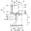
図1および図2に示すように、遠心送風機10は、ケーシング20、およびケーシング20の内部に配置された遠心ファン50を備える。図3に示すように、本実施形態の遠心送風機10は、ケーシング20の内部に遠心ファン50を駆動する電動モータ60が収容されている。
As shown in FIGS. 1 and 2, the
遠心ファン50は、ファン軸心CLfに沿って空気を吸入し、吸入した空気をファン軸心CLfに交差する方向に吹き出すファンである。なお、ファン軸心CLfは、遠心ファン50の回転中心となる軸心である。本実施形態では、ファン軸心CLfに沿って延びる方向をファン軸方向ADと呼ぶと共に、ファン軸心CLfに直交する方向をファン径方向RDと呼ぶことがある。
The
遠心ファン50は、複数のブレード52、複数のブレード52のファン軸方向ADの一方側を連結するファン側板54、複数のブレード52のファン軸方向ADの他方側を連結するファン主板56を含んで構成されている。
The
複数のブレード52は、隣り合うブレード52の間に空気が流通するブレード間通路500が形成されるように、ファン軸心CLfを囲むように並んで配置されている。各ブレード52は、ブレード間通路500における空気の流入部を形成する前縁部521、ブレード間通路500における空気の流出部を形成する後縁部522を有している。本実施形態では、隣り合うブレード52の後縁部522の間に形成される通路が、遠心ファン50における空気流出部53を構成している。
The plurality of
ファン側板54は、中央部が開口するリング状の部材で構成されている。ファン側板54は、各ブレード52におけるファン軸方向ADの一方側の端部が連結されている。ファン側板54には、遠心ファン50の内部に空気を吸い込むファン吸入口541が形成されている。
The
ファン主板56は、円盤状の部材で構成されている。ファン主板56は、各ブレード52におけるファン軸方向ADの他方側の端部が連結されている。ファン主板56の略中央部には、後述する電動モータ60の回転軸62を連結する連結部562が設けられている。連結部562は、回転軸62と共に遠心ファン50が回転するように、遠心ファン50を回転軸62に固定する部位である。
The fan
遠心ファン50は、遠心ファン50を構成する複数のブレード52、ファン側板54、およびファン主板56が一体となるように樹脂成形された一体成形物として構成されている。
The
このように構成される遠心ファン50は、ファン軸心CLfが、上下方向に沿って延びる姿勢で、ケーシング20の内部に収容されている。具体的には、本実施形態の遠心ファン50は、ファン側板54がファン主板56の下方に位置し、ファン吸入口541が下方に向かって開口する姿勢で、ケーシング20の内部に収容されている。
The
ケーシング20は、遠心ファン50を収容すると共に、外部からの空気を遠心ファン50に導く空気導入路240を形成するものである。具体的には、ケーシング20は、遠心ファン50を収容するファン収容部22、空気導入路240を形成する導入路形成部24を含んで構成されている。
The
ファン収容部22は、内部に遠心ファン50が収容された状態で、遠心ファン50のファン径方向RDの外側に渦巻き状の送風路220を形成するスクロールケースで構成されている。
The
ファン収容部22は、ファン軸方向ADにおいて遠心ファン50のファン吸入口541側に対向する対向壁部222を有している。対向壁部222は、ファン径方向RDに沿って延びている。対向壁部222には、その内側端部221に、空気を取り込む空気取込口221aが形成されている。
The
また、図1および図2に示すように、ファン収容部22には、ファン径方向RDの外側に、遠心ファン50からの空気を吹き出すための一対の空気吹出口223a、223bが形成されている。一対の空気吹出口223a、223bは、遠心ファン50を挟んで互いに対向するように形成されている。
Further, as shown in FIGS. 1 and 2, the
さらに、ファン収容部22には、遠心ファン50から吹き出された空気の一部を、電動モータ60を冷却する冷却風として取り込む冷風取込口224が設けられている。冷風取込口224は、ファン収容部22内部の送風路220のうち、最も静圧が高くなり易い舌部225の直後に設けられている。
Further, the
本実施形態のファン収容部22は、上方側分割体226と下方側分割体227と有しており、各分割体226、227をファン軸方向ADに組み付けた組付体で構成されている。ファン収容部22を構成する上方側分割体226および下方側分割体227は、プレスフィット等の結合要素によって組み付けられている。
The
図3に示すように、下方側分割体227は、前述の対向壁部222を含んで構成されている。対向壁部222は、下方側分割体227におけるファン径方向RDに延びる部位である。対向壁部222は、ファン軸方向ADにおいて遠心ファン50と重なり合うファン内側部位228、およびファン内側部位228よりもファン径方向RDの外側に位置するファン外側部位229を有している。そして、対向壁部222のうち、ファン内側部位228に空気取込口221aが形成されている。本実施形態では、ファン内側部位228が、対向壁部222における空気取込口221aを囲む周縁部位を構成している。なお、ファン内側部位228における詳細な構造については後述する。
As shown in FIG. 3, the lower divided
本実施形態の対向壁部222は、ファン内側部位228とファン外側部位229とが別体で構成されている。ファン内側部位228およびファン外側部位229は、互いに結合されている。
In the facing
具体的には、ファン外側部位229には、ファン径方向RDの内側の端部にファン軸方向ADに突き出る凸部229aが設けられている。また、ファン内側部位228には、ファン径方向RDの外側の端部にU字状の溝を有する凹部228aが設けられている。そして、ファン内側部位228およびファン外側部位229は、凹部228aに凸部229aを嵌合した状態で、タッピング等によって連結されている。
Specifically, the fan
本実施形態のファン収容部22は、組付効率やメンテナンス効率を考慮して、ファン内側部位228をファン外側部位229から外すことで、内部に収容された遠心ファン50を取り出すことが可能となっている。すなわち、ファン内側部位228は、ファン軸方向ADにおいて遠心ファン50の外形よりも大きな外形を有している。
In consideration of the assembling efficiency and the maintenance efficiency, the
ファン収容部22には、導入路形成部24が連結されている。導入路形成部24は、下方側分割体227の対向壁部222との間に、外部からの空気をファン軸心CLfと交差する一方向に流して遠心ファン50に導く空気導入路240を形成するものである。空気導入路240は、ファン径方向RDのうち、任意の一方向(例えば、車両の前後方向)に延びている。
An introduction
導入路形成部24は、ファン径方向RDに沿って延びる底壁部241、および底壁部241に連なると共に対向壁部222に連結される側壁部242を有している。導入路形成部24の底壁部241は、対向壁部222全体を覆う大きさを有している。導入路形成部24は、空気導入路240における空気流れ最上流に外部からの空気を取り込むための外部開口部240aが形成されている。
The introduction
このように構成されるケーシング20の内部には、遠心ファン50だけでなく、遠心ファン50を駆動する電動モータ60についても収容されている。本実施形態の電動モータ60は、インナーロータ型のブラシレスモータで構成されている。
Inside the
電動モータ60は、金属で構成された有底筒状の筐体61を備えている。筐体61は、円筒状の筐体筒部611、および筐体筒部611の両端部を閉塞する一対の筐体底部612、613を含んで構成されている。
The
一対の筐体底部612、613それぞれには、回転軸62を回転可能に支持する軸受部63、64が設けられている。また、回転軸62には、永久磁石を含むロータ65が固定されている。ロータ65は、筐体61の内部に配置されている。
一対の筐体底部612、613のうち、ファン側板54側に位置する第1筐体底部612には、その中央部に表裏を貫通する開口部612aが形成されている。第1筐体底部612に設けられた軸受部63は、その下端部が開口部612aを介して筐体61の外部に露出している。
Of the pair of
また、一対の筐体底部612、613のうち、ファン主板56側に位置する第2筐体底部613には、その中央部に表裏を貫通する開口部613aが形成されている。回転軸62は、第2筐体底部613に形成された開口部613aを介して筐体61の外部に露出している。そして、回転軸62における筐体61の外部に露出した部位が、ファン主板56の連結部562に連結されている。
Further, of the pair of
筐体筒部611には、その内側に、コア661にコイル662を巻装した円筒状のステータ66が固定されている。ステータ66は、コア661が筐体筒部611の内周面に当接した状態で、筐体61の内部に配置されている。
A
筐体61の内部におけるファン側板54側には、電気回路としての回路基板67が配置されている。回路基板67には、ロータ65の回転一に応じてコイル662への通電を制御するモータ駆動回路、モータ保護回路等が実装されている。
A
このように構成される電動モータ60は、その一部が遠心ファン50の内側に位置する状態でモータホルダ70に保持されている。モータホルダ70は、電動モータ60の筐体61を保持する有底円筒状のホルダ筒部71、ホルダ筒部71をケーシング20に連結するホルダ連結部72を含んで構成されている。
The
ホルダ筒部71は、遠心ファン50の内側に位置付けられている。ホルダ筒部71の内部には、電動モータ60の筐体61が保持されている。図2に示すように、ホルダ筒部71は、筐体61の外周面と当接する当接部位711と筐体61の外周面と当接しない非当接部位712とが形成されるように、その内周面が凹凸形状となっている。ホルダ筒部71は、当接部位711等によって筐体61を保持する構成となっている。また、ホルダ筒部71と筐体61との間には、非当接部位712によって電動モータ60を冷却する空気を流通させる冷却風通路700が形成されている。
The
ホルダ連結部72は、一端側がホルダ筒部71の外周側から径方向外側に突き出た3つのホルダ脚部721、722、723を有している。各ホルダ脚部721、722、723は、径方向の外側の部位が、他端側がケーシング20の対向壁部222に連結されている。具体的には、各ホルダ脚部721、722、723は、空気取込口221aの一部を遮るように、ホルダ筒部71の径方向の外側に延びている。
The
3つのホルダ脚部721、722、723のうち、ケーシング20の舌部225側に向かって延びるホルダ脚部721は中空状に構成されている。このホルダ脚部721は、その内部に冷風取込口224から取り込まれた冷風を冷却風通路700に導く冷却風導入路721aが形成されている。
Of the three holder leg portions 721, 722, 723, the holder leg portion 721 extending toward the
これにより、遠心ファン50から吹き出された空気の一部は、冷風取込口224から冷却風導入路721aに導入される。そして、冷却風導入路721aを流れる空気は、冷却風通路700を流れた後、遠心ファン50の内側に排気される。このような構造によって、電動モータ60が冷却される。なお、ホルダ連結部72は、4つ以上のホルダ脚部で構成されていてもよい。
As a result, a part of the air blown out from the
次に、ファン内側部位228における詳細な構造について、図3、図4を参照して説明する。図3に示すように、ファン内側部位228には、ファン軸心CLfに沿って延びると共に、対向壁部222側から空気導入路240側に向かって突き出る突出部30が設けられている。
Next, a detailed structure of the fan inside
本実施形態の突出部30は、空気取込口221aを形成する内側端部221に設けられた内側リブ32で構成されている。内側リブ32は、ファン軸心CLfに沿って延びると共に、対向壁部222側から空気導入路240側に向かって突き出ている。
The protruding portion 30 of the present embodiment is configured by the inner rib 32 provided on the
本実施形態の内側リブ32は、空気取込口221aの全周を囲むように環状に構成されている。すなわち、内側リブ32は、ファン内側部位228における空気流れ上流側の領域である上流側周縁部228bおよび上流側周縁部228bよりも空気流れ下流側の下流側周縁部228cの双方に設けられている。なお、上流側周縁部228bは、空気導入路240を流れる空気の流れ方向に直交する方向にファン内側部位228を2つに分けた際に、外部開口部240a側に近い領域である。また、下流側周縁部228cは、ファン内側部位228のうち、上流側周縁部228bよりも外部開口部240aから離れた領域である。
The inner rib 32 of the present embodiment is configured in an annular shape so as to surround the entire circumference of the
内側リブ32は、ファン軸心CLfに沿う方向の寸法である突出高さHriが、その全周において略一定となっている。内側リブ32の突出高さHriは、空気導入路240が確保されるように、内側リブ32の先端部321が導入路形成部24の底壁部241と接しない大きさに設定されている。具体的には、内側リブ32の突出高さHriは、内側リブ32の先端部321と導入路形成部24の底壁部241との間隔Lhi以下となるように設定されている。
The inner rib 32 has a protrusion height Hri, which is a dimension in the direction along the fan axis CLf, substantially constant over the entire circumference. The protruding height Hri of the inner rib 32 is set to a size such that the
また、本実施形態の内側リブ32は、対向壁部222の一部および各ホルダ脚部721、722、723それぞれと一体に構成されている。具体的には、本実施形態の遠心送風機10は、ファン内側部位228、内側リブ32、および各ホルダ脚部721、722、723それぞれが射出成形等による一体成形物として構成されている。
Further, the inner rib 32 of the present embodiment is formed integrally with a part of the facing
ファン内側部位228、内側リブ32、および各ホルダ脚部721、722、723は、一体成形物の製造時にアンダーカットが生じないように、内側リブ32の突出方向において互いに重なり合わないように構成されている。
The fan
次に、本実施形態に係る遠心送風機10の作動を説明する。遠心送風機10は、電動モータ60に対して電力が供給されると、遠心ファン50が回転駆動する。そして、遠心ファン50が空気取込口221aから空気を吸引することで、空気導入路240が負圧になる。
Next, the operation of the
空気導入路240が負圧になると、外部開口部240aから外部の空気が空気導入路240に流入する。外部からの空気は、空気導入路240を図3の矢印F1に示す一方向に流れる。空気導入路240を流れる空気は、図3の矢印F2、F3に示すように、空気取込口221aを介して遠心ファン50に吸入される。この際、図3の矢印F2に示すように上流側周縁部228b側から遠心ファン50の内部に流れる空気は、その向きが略180°ターンするように変化する。
When the
遠心ファン50に吸入された空気は、図3の矢印F4に示すように、遠心ファン50の空気流出部53からファン収容部22の送風路220に吹き出される。そして、送風路220に吹き出された空気は、一対の空気吹出口223a、223bからケーシング20の外部に吹き出される。
The air sucked into the
ここで、図5は、本実施形態の比較例となる遠心送風機CEにおける遠心ファン50内部の空気の流れを示している。比較例となる遠心送風機CEは、ファン内側部位228に対して突出部30が設けられていない点が、第1実施形態と相違している。なお、説明の便宜上、図5では、比較例の遠心送風機CEにおける本実施形態の遠心送風機10と同様の構成に対して同一の参照符号を付している。
Here, FIG. 5 has shown the flow of the air inside the
図5に示すように、比較例の遠心送風機CEでは、上流側周縁部228b側から流入した空気の向きが遠心ファン50の内部で略180°ターンするように急激に変化する。この際、気流の慣性によって、遠心ファン50のブレード52のファン主板56側に空気の流れが偏ってしまう。このような空気の流れの偏りが生ずると、遠心ファン50のブレード52のファン側板54側に殆ど空気が流れず、遠心ファン50の内部に空気の送風に寄与しない死水域DWが生ずることで、遠心送風機CEにおけるファン効率が低下してしまう。
As shown in FIG. 5, in the centrifugal blower CE of the comparative example, the direction of the air that has flowed in from the upstream side peripheral edge portion 228b side suddenly changes so as to make an approximately 180 ° turn inside the
これに対して、本実施形態の遠心送風機10は、ファン内側部位228に、ファン軸心CLfに沿って延びると共に、対向壁部222側から空気導入路240側に向かって突き出る突出部30が設けられている。具体的には、突出部30は、空気取込口221aを形成する内側端部221に設けられた内側リブ32で構成されている。
On the other hand, in the
これによると、図6に示すように、突出部30を構成する内側リブ32によって、遠心ファン50に吸入される直前に空気の向きをファン軸線CLfに沿う方向に転向させることができる。すなわち、本実施形態の遠心送風機10では、遠心ファン50の内部で空気の流れる向きが急激に変化してしまうことを抑えることができる。このため、本実施形態の遠心送風機10によれば、遠心ファン50の内部に生ずる死水域DWを小さくして、遠心送風機10のファン効率の向上を図ることができる。
According to this, as shown in FIG. 6, the direction of the air can be turned to the direction along the fan axis line CLf immediately before being sucked into the
また、本実施形態では、突出部30を構成する内側リブ32の突出高さHriは、内側リブ32の先端部321と導入路形成部24の底壁部241との間隔Lhi以下となるように設定している。これによると、空気導入路240を充分に確保しつつ、遠心ファン50の内部で空気の流れる向きが急激に変化してしまうこと抑制することができる。
Further, in the present embodiment, the protrusion height Hri of the inner rib 32 that constitutes the protrusion 30 is set to be equal to or less than the interval Lhi between the
さらに、本実施形態の電動モータ60は、少なくとも一部が、遠心ファン50の内側に位置するように、モータホルダ70に保持されている。このように、電動モータ60の一部を遠心ファン50の内側に位置付ける構成とすれば、ファン軸方向ADの体格を抑えることができる。
Further, the
ここで、本実施形態の遠心送風機10は、ファン内側部位228、内側リブ32、および各ホルダ脚部721、722、723それぞれが射出成形等による一体成形物として構成されている。これによると、遠心送風機10における部品点数を低減させることができる。特に、突出部30を構成する内側リブ32がファン軸心CLfに沿って延びている構成では、ファン内側部位228、内側リブ32、および各ホルダ脚部721、722、723を構成する一体成形物の製造時にアンダーカットが生じ難いといった利点がある。
Here, in the
(第2実施形態)
次に、第2実施形態について、図7〜図9を参照して説明する。本実施形態の遠心送風機10は、対向壁部222に設けられた突出部30が、内側リブ32および外側リブ34で構成されている。なお、内側リブ32は、第1実施形態と同様に構成されるため、その説明を省略する。
(Second embodiment)
Next, a second embodiment will be described with reference to FIGS. In the
図7に示すように、外側リブ34は、対向壁部222のうち、内側リブ32よりもファン径方向RDの外側の部位に設けられている。なお、図7は、第1実施形態で示した図2に対応する図である。
As shown in FIG. 7, the outer rib 34 is provided at a portion of the opposing
外側リブ34は、空気取込口221aの全周を囲むように環状に構成されている。具体的には、外側リブ34は、ファン内側部位228における上流側周縁部228bおよび下流側周縁部228cの双方に設けられている。本実施形態の外側リブ34は、内側リブ32と同心円となるように構成されている。なお、外側リブ34は、内側リブ32と同心円になっていなくてもよい。外側リブ34は、その中心が内側リブ32の中心とずれていてもよい。
The outer rib 34 is formed in an annular shape so as to surround the entire circumference of the
本実施形態の外側リブ34は、図8に示すように、ファン内側部位228のうち、各ブレード52の後縁部522よりも外側に位置する部位に設けられている。具体的には、外側リブ34は、ファン内側部位228における径方向外側の外側端部に設けられている。これにより、外側リブ34は、ファン軸方向ADにおいて、遠心ファン50と重なり合わない構成となっている。なお、図8は、第1実施形態で示した図3に対応する図である。
As shown in FIG. 8, the outer rib 34 of the present embodiment is provided at a portion of the fan
外側リブ34は、ファン軸心CLfに沿って延びると共に、対向壁部222側から空気導入路240側に向かって突き出ている。外側リブ34は、ファン軸心CLfに沿う方向の寸法である突出高さHroが、その全周において略一定となっている。そして、外側リブ34は、突出高さHroが、外側リブ34の先端部341と導入路形成部24の底壁部241との間隔Lho以下となるように設定されている。本実施形態の遠心送風機10は、内側リブ32の突出高さHriと外側リブ34の突出高さHroとが同等の大きさに設定されている。
The outer ribs 34 extend along the fan axis CLf and project from the facing
また、外側リブ34は、対向壁部222のファン内側部位228と一体に構成されている。本実施形態のファン内側部位228、内側リブ32、外側リブ34、および各ホルダ脚部721、722、723は、一体成形物の製造時にアンダーカットが生じないように、各リブ32、34の突出方向において互いに重なり合わないように構成されている。
Further, the outer rib 34 is integrally formed with the fan
その他の構成は、第1実施形態と同様である。本実施形態の遠心送風機10は、ファン内側部位228に、ファン軸心CLfに沿って延びると共に、対向壁部222側から空気導入路240側に向かって突き出る突出部30が設けられている。具体的には、突出部30は、空気取込口221aを形成する内側端部221に設けられた内側リブ32、および内側リブ32よりも外側に設けられた外側リブ34で構成されている。
Other configurations are similar to those of the first embodiment. In the
これによると、図9に示すように、突出部30を構成する外側リブ34によって、空気導入路240を流れる空気が、ファン軸方向ADにおいて、遠心ファン50のファン吸入口541から遠ざかる。そして、空気導入路240を流れる空気は、内側リブ32によって、遠心ファン50に吸入される前にファン軸線CLfに沿う方向に転向する。このように、本実施形態の遠心送風機10では、遠心ファン50に吸入される前の段階で、空気の向きをファン軸線CLfに沿う方向に転向させることができるので、遠心ファン50の内部で空気の流れる向きが急激に変化してしまうことを抑えることができる。
According to this, as shown in FIG. 9, the air flowing through the
このため、本実施形態の遠心送風機10によれば、第1実施形態と同様に、遠心ファン50の内部に生ずる死水域DWを小さくして、遠心送風機10のファン効率の向上を図ることができる。
Therefore, according to the
特に、本実施形態では、対向壁部222のうち、ファン径方向RDにおいて、各ブレード52の後縁部522よりも外側に位置する部位に外側リブ34を設けている。これによると、空気導入路240の上流側を流れる空気を、ファン軸方向ADにおいてファン吸入口541から遠ざけることができるので、遠心ファン50に流入する前に、空気の向きをファン軸方向ADに転向させる区間を充分に確保することができる。この結果、遠心ファン50の内部で空気の流れる向きが急激に変化してしまうことを一層抑制することができる。
In particular, in the present embodiment, the outer rib 34 is provided at a portion of the facing
また、本実施形態の遠心送風機10では、外側リブ34の突出高さHroを、外側リブ34の先端部341と導入路形成部24の底壁部241との間隔Lho以下となるように設定している。これによると、空気導入路240を充分に確保しつつ、遠心ファン50の内部で空気の流れる向きが急激に変化してしまうこと抑制することができる。
Further, in the
さらに、本実施形態の遠心送風機10は、ファン内側部位228、内側リブ32、外側リブ34、および各ホルダ脚部721、722、723それぞれが射出成形等による一体成形物として構成されている。これによると、遠心送風機10における部品点数を低減させることができる。特に、突出部30を構成する各リブ32、34が、ファン軸心CLfに沿って延びている構成では、一体成形物の製造時にアンダーカットが生じ難いといった利点がある。
Further, in the
(第3実施形態)
次に、第3実施形態について、図10、図11を参照して説明する。本実施形態では、本実施形態の遠心送風機10は、対向壁部222に複数の外側リブ34A、34Bが設けられている点が、第1、第2実施形態と相違している。
(Third Embodiment)
Next, a third embodiment will be described with reference to FIGS. In the present embodiment, the
図10に示すように、遠心送風機10は、対向壁部222に対して、内側リブ32よりも外側に第1外側リブ34Aが設けられると共に、第1外側リブ34Aよりも外側に第2外側リブ34Bが設けられている。なお、図10は、第1実施形態で示した図2に対応する図である。
As shown in FIG. 10, in the
第1外側リブ34Aは、対向壁部222における内側リブ32よりもファン径方向RDの外側の部位に設けられている。また、第2外側リブ34Bは、対向壁部222における第1外側リブ34Aよりもファン径方向RDの外側の部位に設けられている。各外側リブ34A、34Bは、空気取込口221aの全周を囲むように環状に構成されている。本実施形態の各外側リブ34A、34Bは、内側リブ32と同心円となるように構成されている。なお、各外側リブ34A、34Bは、内側リブ32と同心円となっていなくてもよい。各外側リブ34A、34Bは、その中心が内側リブ32の中心とずれていてもよい。
The first outer rib 34A is provided on a portion of the opposing
本実施形態の第1外側リブ34Aは、図11に示すように、ファン内側部位228のうち、各ブレード52の後縁部522よりも外側に位置する部位に設けられている。具体的には、第1外側リブ34Aは、ファン内側部位228における径方向外側の外側端部に設けられている。なお、第1外側リブ34Aは、第2実施形態の外側リブ34と同様に、対向壁部222のファン内側部位228と一体に構成されている。
As shown in FIG. 11, the first outer rib 34 </ b> A of the present embodiment is provided at a portion of the fan
また、本実施形態の第2外側リブ34Bは、ファン内側部位228ではなくファン外側部位229に設けられている。これにより、各外側リブ34A、34Bは、ファン軸方向ADにおいて、遠心ファン50と重なり合わない構成となっている。本実施形態の第2外側リブ34Bは、ファン外側部位229と一体に構成されている。なお、第2外側リブ34Bは、各ホルダ脚部721、722、723とは別体で構成されている。
Further, the second outer rib 34B of the present embodiment is provided not on the fan
各外側リブ34A、34Bは、ファン軸心CLfに沿って延びると共に、対向壁部222側から空気導入路240側に向かって突き出ている。各外側リブ34A、34Bは、ファン軸心CLfに沿う方向の寸法である突出高さHro1、Hro2が、その全周において略一定となっている。
The outer ribs 34A and 34B extend along the fan axis CLf and project from the facing
本実施形態の第1外側リブ34Aは、突出高さHro1が、第1外側リブ34Aの先端部341Aと導入路形成部24の底壁部241との間隔Lho1以下となるように設定されている。
The protrusion height Hro1 of the first outer rib 34A of the present embodiment is set to be less than or equal to the interval Lho1 between the
一方、本実施形態の第2外側リブ34Bは、突出高さHro2が、第1外側リブ34Aの突出高さHro1よりも小さくなっている。これにより、第2外側リブ34Bの先端部341Bと導入路形成部24の底壁部241との間隔Lho2は、第1外側リブ34Aの先端部341Aと導入路形成部24の底壁部241との間隔Lho1よりも大きくなっている。
On the other hand, the protrusion height Hro2 of the second outer rib 34B of the present embodiment is smaller than the protrusion height Hro1 of the first outer rib 34A. As a result, the distance Lho2 between the
さらに、本実施形態の内側リブ32は、突出高さHriが、第1外側リブ34Aの突出高さHro1よりも小さくなっている。すなわち、本実施形態の内側リブ32は、突出高さHriが、隣り合う第1外側リブ34Aの突出高さHro1よりも小さくなっている。 Further, the protrusion height Hri of the inner rib 32 of the present embodiment is smaller than the protrusion height Hro1 of the first outer rib 34A. That is, the protrusion height Hri of the inner rib 32 of the present embodiment is smaller than the protrusion height Hro1 of the adjacent first outer rib 34A.
これにより、内側リブ32の先端部321と導入路形成部24の底壁部241との間隔Lhiは、第1外側リブ34Aの先端部341Aと導入路形成部24の底壁部241との間隔Lho1よりも大きくなっている。
Thereby, the distance Lhi between the
本実施形態の内側リブ32は、突出高さHriが、第2外側リブ34Bの突出高さHro2と同様の大きさとなっている。なお、内側リブ32は、突出高さHriが、第2外側リブ34Bの突出高さHro2と異なる大きさとなっていてもよい。 The protrusion height Hri of the inner rib 32 of the present embodiment is the same as the protrusion height Hro2 of the second outer rib 34B. In addition, the protrusion height Hri of the inner rib 32 may be different from the protrusion height Hro2 of the second outer rib 34B.
その他の構成は、第1、第2実施形態と同様である。本実施形態の遠心送風機10は、対向壁部222に、ファン軸心CLfに沿って延びると共に、対向壁部222側から空気導入路240側に向かって突き出る突出部30が設けられている。具体的には、突出部30は、対向壁部222に設けられた内側リブ32および各外側リブ34A、34Bで構成されている。
Other configurations are similar to those of the first and second embodiments. In the
これによると、図11に示すように、突出部30を構成する各外側リブ34A、Bによって、空気導入路240を流れる空気が、ファン軸方向ADにおいて、遠心ファン50のファン吸入口541から遠ざかる。そして、空気導入路240を流れる空気は、内側リブ32によって、遠心ファン50に吸入される前にファン軸線CLfに沿う方向に転向する。
According to this, as shown in FIG. 11, the air flowing through the
このように、本実施形態の遠心送風機10では、遠心ファン50に吸入される前の段階で、空気の向きをファン軸線CLfに沿う方向に転向させることができるので、遠心ファン50の内部で空気の流れる向きが急激に変化してしまうことを抑えることができる。
As described above, in the
以上の如く、本実施形態の遠心送風機10によれば、第1、第2実施形態と同様に、遠心ファン50の内部に生ずる死水域DWを小さくして、遠心送風機10のファン効率の向上を図ることができる。
As described above, according to the
特に、本実施形態では、第2外側リブ34Bの突出高さHroが、第1外側リブ34Aの突出高さHro1よりも小さくなっている。これによると、空気導入路240の上流側を流れる空気を、ファン軸方向ADにおいてファン吸入口541から徐々に遠ざけることができるので、空気導入路240における圧力損失を抑えることができる。
In particular, in this embodiment, the protrusion height Hro of the second outer rib 34B is smaller than the protrusion height Hro1 of the first outer rib 34A. According to this, the air flowing on the upstream side of the
さらに、本実施形態では、内側リブ32の突出高さHriが、隣り合う第1外側リブ34Aの突出高さHro1よりも小さくなっている。これによると、空気導入路240を流れる空気が第1外側リブ34Aおよび内側リブ32によって徐々にファン吸入口541側に導かれるので、空気導入路240における圧力損失を抑えることができる。
Further, in the present embodiment, the protrusion height Hri of the inner rib 32 is smaller than the protrusion height Hro1 of the adjacent first outer rib 34A. According to this, the air flowing through the
したがって、本実施形態の遠心送風機10によれば、空気導入路240における圧力損失を抑えつつ、遠心ファン50の内部で空気の流れる向きが急激に変化してしまうことを一層抑制することができる。
Therefore, according to the
ここで、本実施形態では、内側リブ32の外側に2つの外側リブ34A、34Bを設けた構成を例示したが、これに限定されない。遠心送風機10は、外側リブ34が内側リブ32の外側において3つ以上設けられた構成となっていてもよい。
Here, in the present embodiment, the configuration in which the two outer ribs 34A and 34B are provided on the outer side of the inner rib 32 is illustrated, but the configuration is not limited to this. The
(第4実施形態)
次に、第4実施形態について、図12を参照して説明する。本実施形態では、突出部30を構成する内側リブ32の突出高さHriを周方向において変化させている点が第1実施形態と異なっている。
(Fourth Embodiment)
Next, a fourth embodiment will be described with reference to FIG. The present embodiment is different from the first embodiment in that the protrusion height Hri of the inner rib 32 forming the protrusion 30 is changed in the circumferential direction.
図12に示すように、本実施形態の内側リブ32は、ファン内側部位228の上流側周縁部228bにおける突出高さHri1が、下流側周縁部228cにおける突出高さHri2よりも大きくなっている。具体的には、本実施形態の内側リブ32は、突出高さHriが空気流れ上流側から下流側に向かって徐々に小さくなっている。
As shown in FIG. 12, in the inner rib 32 of the present embodiment, the protruding height Hri1 at the upstream side peripheral edge portion 228b of the fan
その他の構成は、第1実施形態と同様である。本実施形態の遠心送風機10によれば、第1実施形態と共通の構成から奏される作用効果を第1実施形態と同様に得ることができる。
Other configurations are similar to those of the first embodiment. According to the
本実施形態の内側リブ32は、空気流れ上流側に位置する部位の突出高さHri1が、空気流れ下流側に位置する部位の突出高さHri2に比べて大きくなっている。換言すれば、内側リブ32は、空気流れ下流側に位置する部位の突出高さHri2が、空気流れ上流側に位置する部位の突出高さHri1に比べて小さくなっている。 In the inner rib 32 of the present embodiment, the protruding height Hri1 of the portion located on the upstream side of the air flow is larger than the protruding height Hri2 of the portion located on the downstream side of the air flow. In other words, in the inner rib 32, the protruding height Hri2 of the portion located on the downstream side of the air flow is smaller than the protruding height Hri1 of the portion located on the upstream side of the air flow.
これによると、上流側周縁部228bよりも空気流れ下流側に位置する部位における空気の流れが突出部30によって変化してしまうことが抑えられる。このため、上流側周縁部228bよりも空気流れ下流側に位置する下流側周縁部228cから遠心ファン50に流入する空気の流量を確保することができる。
According to this, it is possible to prevent the protrusion 30 from changing the air flow in a portion located on the downstream side of the upstream side peripheral portion 228b in the air flow direction. Therefore, it is possible to secure the flow rate of the air flowing into the
特に、本実施形態の内側リブ32は、空気流れ上流側から下流側に向かって突出高さHriが徐々に小さくなっている。これによると、内側リブ32による空気流れの変化が上流側周縁部228b側から空気流れ下流側に向かって徐々に小さくなるので、突出部30の追加に伴う空気導入路240における圧力損失を充分に抑制することができる。
In particular, the protrusion height Hri of the inner rib 32 of the present embodiment gradually decreases from the upstream side of the air flow toward the downstream side. According to this, the change in the air flow due to the inner ribs 32 gradually decreases from the upstream peripheral edge 228b side toward the air flow downstream side, so that the pressure loss in the
ここで、第2、第3実施形態の如く、突出部30が内側リブ32および外側リブ34で構成されている場合、外側リブ34についても、空気流れ上流側から下流側に向かって突出高さHroを小さくすることが望ましい。すなわち、突出部30は、空気流れ上流側から下流側に向かって突出高さが小さくなっていることが望ましい。 Here, when the protruding portion 30 is formed of the inner rib 32 and the outer rib 34 as in the second and third embodiments, the protruding height of the outer rib 34 also increases from the air flow upstream side to the downstream side. It is desirable to reduce Hro. That is, it is desirable that the protruding portion 30 has a smaller protruding height from the upstream side of the air flow toward the downstream side.
(第5実施形態)
次に、第5実施形態について、図13を参照して説明する。本実施形態では、突出部30を構成する内側リブ32を下流側周縁部228cの一部に設けない構成となっている点が第4実施形態と異なっている。
(Fifth Embodiment)
Next, a fifth embodiment will be described with reference to FIG. The present embodiment is different from the fourth embodiment in that the inner rib 32 forming the protruding portion 30 is not provided in a part of the downstream side peripheral edge portion 228c.
図13に示すように、本実施形態のファン内側部位228には、下流側周縁部228cにおける空気流れ最下流部に内側リブ32が設けられていない構成となっている。すなわち、下流側周縁部228cにおける空気流れ最下流部は、ファン軸方向ADに対して突出していない構成となっている。
As shown in FIG. 13, the fan
その他の構成は、第4実施形態と同様である。本実施形態の遠心送風機10によれば、第4実施形態と共通の構成から奏される作用効果を第4実施形態と同様に得ることができる。
Other configurations are the same as those in the fourth embodiment. According to the
本実施形態の遠心送風機10は、下流側周縁部228cにおける空気流れ最下流部に内側リブ32を設けていないので、下流側周縁部228cの空気流れ最下流部から遠心ファン50に流入する空気の流量を確保することができる。
In the
ここで、本実施形態では、ファン内側部位228のうち、下流側周縁部228cにおける空気流れ最下流部に内側リブ32を設けない構成について説明したが、これに限定されない。遠心送風機10は、ファン内側部位228のうち、上流側周縁部228bに内側リブ32が設けられ、下流側周縁部228cに内側リブ32が設けられていない構成となっていてもよい。
Here, in the present embodiment, the configuration in which the inner rib 32 is not provided at the most downstream portion of the air flow in the downstream peripheral portion 228c of the fan
(第6実施形態)
次に、第6実施形態について、図14〜図18を参照して説明する。本実施形態では、空気取込口221aの内側端部221以外の部位に内側リブ32Aが設けられている点が第1実施形態と異なっている。
(Sixth Embodiment)
Next, a sixth embodiment will be described with reference to FIGS. The present embodiment is different from the first embodiment in that an inner rib 32A is provided at a portion other than the
図14および図15に示すように、本実施形態の遠心送風機10は、ファン内側部位228のうち空気取込口221aに連なる部位に空気導入路240側に向かって隆起するように湾曲する湾曲部25が設けられている。湾曲部25は、ファン内側部位228に沿って流れる空気の剥離を抑制して、空気導入路240を流れる空気を遠心ファン50の内側に円滑に導くために設けられている。
As shown in FIGS. 14 and 15, in the
湾曲部25は、ファン内側部位228において空気取込口221aの全周を囲むように形成されている。湾曲部25は、ファン側板54の一部が覆われるように、その断面が略円弧状の形状になっている。なお、湾曲部25は、その断面が滑らかに湾曲している形状であれば、略円弧状の形状以外の形状になっていてもよい。
The
遠心送風機10には、ファン内側部位228のうち空気取込口221aの内側端部221よりも外側に内側リブ32Aが設けられている。すなわち、内側リブ32Aは、内側端部221に設けられていない。
The
内側リブ32Aは、ファン軸心CLfに沿って延びると共に、対向壁部222側から空気導入路240側に向かって突き出ている。内側リブ32Aは、その突出高さHriが、内側リブ32Aの先端部321と導入路形成部24の底壁部241との間隔Lhi以下となるように設定されている。
The inner rib 32A extends along the fan axis CLf and projects from the facing
本実施形態の内側リブ32Aは、湾曲部25の頂部250に設けられている。具体的には、内側リブ32Aは、その根元となる部位が湾曲部25の頂部250に位置付けられている。
The inner rib 32A of the present embodiment is provided on the top 250 of the
内側リブ32Aは、図16に示すように、その根元となる部位の略中央部分が湾曲部25の頂部250となるように設けられている。すなわち、内側リブ32Aは、その根元となる部位における内面と外面との略中央部が湾曲部25の頂部250となるように、湾曲部25に対して設けられている。
As shown in FIG. 16, the inner rib 32 </ b> A is provided so that the substantially central portion of the base portion thereof becomes the top 250 of the
ここで、湾曲部25の頂部250は、ファン軸方向ADにおいて湾曲部25における最も空気取込口221aから離れた部位である。換言すれば、湾曲部25の頂部250は、ファン径方向RDにおいて湾曲部25における他の部位と重なり合わない部位である。
Here, the
また、内側リブ32Aが湾曲部25の頂部250に設けられている状態は、ファン軸方向ADにおいて内側リブ32Aの少なくとも一部が頂部250と重なり合っている状態として解釈することができる。具体的には、図17に示すように、内側リブ32Aの外側面と湾曲部25の頂部250とがファン軸方向ADから見たときに重なり合っている状態も、内側リブ32Aが湾曲部25の頂部250に設けられている状態と解釈することができる。また、図18に示すように、内側リブ32Aの内側面と湾曲部25の頂部250とがファン軸方向ADから見たときに重なり合っている状態も、内側リブ32Aが湾曲部25の頂部250に設けられている状態と解釈することができる。
The state where the inner rib 32A is provided on the top 250 of the
その他の構成は、第1実施形態と同様である。本実施形態の遠心送風機10は、ファン内側部位228に内側リブ32Aが設けられている。このため、第1実施形態と同様に、内側リブ32Aによって、遠心ファン50に吸入される直前に空気の向きをファン軸線CLfに沿う方向に転向させることができる。
Other configurations are similar to those of the first embodiment. In the
特に、本実施形態の遠心送風機10は、内側リブ32Aが空気取込口221aに連なる湾曲部25の頂部250に設けられている。これによると、湾曲部25におけるコアンダ効果によって空気の向きを遠心ファン50に吸入され易い向きに転向させることが期待できる。
Particularly, in the
このように、本実施形態の遠心送風機10は、内側リブ32Aおよび湾曲部25における頂部250よりも内側の部位の双方によって、遠心ファン50に吸入される空気の向きを遠心ファン50に吸入され易い向きに転向させることができる。
As described above, in the
(第6実施形態の変形例)
上述の第6実施形態では、内側リブ32Aを湾曲部25の頂部250に設けたものを例示したが、これに限定されない。遠心送風機10は、例えば、ファン内側部位228のうち湾曲部25の頂部250から内側端部221までの範囲に設けられていてもよい。すなわち、遠心送風機10は、ファン内側部位228における湾曲部25の頂部250よりも内側に設けられていてもよい。
(Modification of Sixth Embodiment)
In the above-described sixth embodiment, the inner rib 32A is provided on the top 250 of the bending
上述の第6実施形態では、ファン内側部位228に対して内側リブ32Aが設けられ、外側リブ34が設けられていないものを例示したが、これに限定されない。遠心送風機10は、例えば、ファン内側部位228に対して内側リブ32Aおよび外側リブ34の双方が設けられた構成になっていてもよい。この場合、外側リブ34については、ファン内側部位228における内側リブ32Aよりもファン径方向RDの外側に設定すればよい。
In the above-described sixth embodiment, an example in which the inner rib 32A is provided for the fan
(第7実施形態)
次に、第7実施形態について、図19を参照して説明する。本実施形態では、突出部30を構成する外側リブ34Cを下流側周縁部228cの一部に設けない構成となっている点が第2実施形態と異なっている。
(Seventh embodiment)
Next, a seventh embodiment will be described with reference to FIG. The present embodiment is different from the second embodiment in that the outer rib 34C forming the protruding portion 30 is not provided in a part of the downstream side peripheral edge portion 228c.
図19に示すように、本実施形態のファン内側部位228には、下流側周縁部228cにおける空気流れ下流側に外側リブ34Cが設けられていない構成となっている。すなわち、外側リブ34Cは、ファン内側部位228における上流側周縁部228bおよび下流側周縁部228cにおける空気流れ上流側に設けられている。具体的には、外側リブ34Cは、上流側周縁部228bから下流側周縁部228cに位置するホルダ脚部721、722までの範囲に設けられている。
As shown in FIG. 19, the fan
その他の構成は、第2実施形態と同様である。本実施形態の遠心送風機10によれば、第2実施形態と共通の構成から奏される作用効果を第2実施形態と同様に得ることができる。
Other configurations are similar to those of the second embodiment. According to the
本実施形態の遠心送風機10は、下流側周縁部228cにおける空気流れ下流側に外側リブ34Cを設けていないので、下流側周縁部228cの空気流れ下流側から遠心ファン50に流入する空気の流量を確保することができる。
In the
(第7実施形態の変形例)
上述の第7実施形態では、ファン内側部位228のうち、下流側周縁部228cにおける空気流れ下流側に外側リブ34Cを設けない構成について説明したが、これに限定されない。遠心送風機10は、例えば、ファン内側部位228のうち、上流側周縁部228bに外側リブ34Cが設けられ、下流側周縁部228cに外側リブ34Cが設けられていない構成となっていてもよい。
(Modification of Seventh Embodiment)
In the above-described seventh embodiment, the configuration in which the outer rib 34C is not provided on the downstream side peripheral portion 228c on the downstream side of the air flow in the fan
上述の第7実施形態では、上流側周縁部228bおよび下流側周縁部228cの双方に内側リブ32が設けられているものを例示したが、これに限定されない。遠心送風機10は、例えば、第5実施形態の如く、下流側周縁部228cの少なくとも一部に内側リブ32が設けられていない構成になっていてもよい。
In the above-described seventh embodiment, the inner rib 32 is provided on both the upstream peripheral edge 228b and the downstream peripheral edge 228c, but the invention is not limited to this. The
(他の実施形態)
以上、本発明の代表的な実施形態について説明したが、本発明は、上述の実施形態に限定されることなく、例えば、以下のように種々変形可能である。
(Other embodiments)
Although the representative embodiments of the present invention have been described above, the present invention is not limited to the above-described embodiments, and various modifications can be made as follows, for example.
上述の各実施形態では、突出部30が、少なくとも内側リブ32を含んで構成される例について説明したが、これに限定されない。突出部30は、例えば、外側リブ34だけで構成されていてもよい。突出部30を外側リブ34だけで構成する場合、当該外側リブ34は、ファン内側部位228における空気取込口221aを形成する内側端部221よりも外側に設けられることになる。
In each of the above-described embodiments, the example in which the protrusion 30 is configured to include at least the inner rib 32 has been described, but the present invention is not limited to this. The protrusion 30 may be composed of only the outer rib 34, for example. When the protrusion 30 is composed of only the outer ribs 34, the outer ribs 34 are provided outside the
上述の各実施形態の如く、突出部30を構成する内側リブ32の突出高さHriを、内側リブ32の先端部321と導入路形成部24の底壁部241との間隔Lhi以下となるように設定することが望ましいが、これに限定されない。内側リブ32は、例えば、突出高さHriが、内側リブ32の先端部321と導入路形成部24の底壁部241との間隔Lhiよりも大きくなるように設定されていてもよい。
As in each of the above-described embodiments, the protrusion height Hri of the inner rib 32 that configures the protrusion 30 is set to be equal to or less than the distance Lhi between the
上述の各実施形態では、ファン内側部位228、内側リブ32、各ホルダ脚部721、722、723等を一体成形物として構成する例について説明したが、これに限定されない。遠心送風機10は、例えば、ファン内側部位228、内側リブ32、各ホルダ脚部721、722、723等が別体で構成されていてもよい。
In each of the above-described embodiments, an example in which the fan
上述の各実施形態では、電動モータ60の少なくとも一部が遠心ファン50の内側に位置付けられた構成について説明したが、これに限定されない。遠心送風機10は、例えば、電動モータ60が遠心ファン50の外側に位置付けられた構成となっていてもよい。
In each of the above-described embodiments, the configuration in which at least a part of the
上述の各実施形態では、本発明の遠心送風機10を、車室内の空気を循環させるサーキュレータに適用した例について説明したが、これに限定されない。本発明の遠心送風機10は、例えば、車両用空調装置の送風装置、シート空調装置の送風装置に対して適用することができる。また、本発明の遠心送風機10は、車両だけでなく、家屋や工場等に利用される送風装置等にも広く適用可能である。
In each of the above-described embodiments, the example in which the
上述の実施形態において、実施形態を構成する要素は、特に必須であると明示した場合および原理的に明らかに必須であると考えられる場合等を除き、必ずしも必須のものではないことは言うまでもない。 It goes without saying that, in the above-described embodiments, the elements constituting the embodiments are not necessarily essential unless explicitly stated as essential or in principle considered to be essential.
上述の実施形態において、実施形態の構成要素の個数、数値、量、範囲等の数値が言及されている場合、特に必須であると明示した場合および原理的に明らかに特定の数に限定される場合等を除き、その特定の数に限定されない。 In the above-described embodiment, when numerical values such as the number, numerical value, amount, range, etc. of the constituent elements of the embodiment are referred to, when explicitly stated to be indispensable and in principle limited to a specific number It is not limited to the specific number except for cases.
上述の実施形態において、構成要素等の形状、位置関係等に言及するときは、特に明示した場合および原理的に特定の形状、位置関係等に限定される場合等を除き、その形状、位置関係等に限定されない。 In the above-described embodiment, when referring to the shapes and positional relationships of constituent elements and the like, the shapes and positional relationships are excluded unless otherwise specified and in principle limited to specific shapes and positional relationships. It is not limited to the above.
(まとめ)
上述の実施形態の一部または全部で示された第1の観点によれば、遠心送風機は、ケーシングおよび遠心ファンを備える。ケーシングは、遠心ファンのファン吸入口側に対向する対向壁部に空気を取り込む空気取込口が形成されたファン収容部を有している。また、ケーシングは、対向壁部との間に、外部からの空気をファン軸心と交差する一方向に流して遠心ファンに導く空気導入路を形成する導入路形成部を有している。そして、対向壁部には、少なくとも空気取込口を囲む周縁部位のうち、空気導入路の空気流れ上流側に位置する上流側周縁部に、ファン軸心に沿って延びると共に、対向壁部側から空気導入路側に向かって突き出る突出部が形成されている。
(Summary)
According to the first aspect shown in some or all of the above-described embodiments, the centrifugal blower includes a casing and a centrifugal fan. The casing has a fan accommodating portion in which an air intake opening for taking in air is formed in a facing wall portion facing the fan intake opening side of the centrifugal fan. In addition, the casing has an introduction passage forming portion that forms an air introduction passage that is provided between the casing and the opposing wall portion and that introduces air from the outside in one direction that intersects the fan axis and guides the air to the centrifugal fan. In the opposing wall portion, at least the peripheral portion surrounding the air intake port extends along the fan axis to the upstream peripheral portion located on the upstream side of the air flow in the air introduction passage, and the opposing wall portion side. A protruding portion is formed to protrude from the air introduction path side.
また、第2の観点によれば、遠心送風機は、周縁部位のうち空気取込口に連なる部位に空気導入路側に向かって隆起するように湾曲する湾曲部が設けられている。そして、突出部は、周縁部位における湾曲部の頂点または湾曲部の頂点よりも内側に設けられた内側リブを含んで構成されている。 Further, according to the second aspect, in the centrifugal blower, a curved portion that is curved so as to bulge toward the air introduction path side is provided in a peripheral portion that is continuous with the air intake port. The protruding portion is configured to include an apex of the curved portion at the peripheral edge portion or an inner rib provided inside the apex of the curved portion.
これによると、内側リブによって、遠心ファンに吸入される直前に空気の向きをファン軸線に沿う方向に転向させることができるので、遠心ファンの内部に生ずる死水域が生じてしまうことを充分に抑制することができる。また、内側リブを湾曲部の頂点または当該頂点と空気吸込口との間に設ける場合、湾曲部におけるコアンダ効果によって空気の向きを遠心ファンに吸入され易い向きに転向させることが期待できる。 According to this, since the inner ribs can redirect the air to the direction along the fan axis immediately before being sucked into the centrifugal fan, it is possible to sufficiently prevent the dead water region generated inside the centrifugal fan from occurring. can do. Further, when the inner rib is provided at the apex of the curved portion or between the apex and the air suction port, it can be expected that the Coanda effect in the curved portion changes the direction of the air to the direction in which the centrifugal fan is easily sucked.
また、第3の観点によれば、遠心送風機の内側リブは、対向壁部における空気取込口を形成する内側端部に設けられている。これによると、内側リブによって、遠心ファンに吸入される直前に空気の向きをファン軸線に沿う方向に転向させることができるので、遠心ファンの内部に生ずる死水域が生じてしまうことを充分に抑制することができる。 Further, according to the third aspect, the inner rib of the centrifugal blower is provided at the inner end portion that forms the air intake port in the facing wall portion. According to this, since the inner ribs can redirect the air to the direction along the fan axis immediately before being sucked into the centrifugal fan, it is possible to sufficiently prevent the dead water region generated inside the centrifugal fan from occurring. can do.
また、第4の観点によれば、遠心送風機の突出部は、対向壁部のうち、内側リブよりも外側に設けられた1つ以上の外側リブを含んで構成されている。これによると、外側リブによって、空気導入路を流れる空気が、ファン軸心に沿う方向においてファン吸込口から遠ざかるので、遠心ファンの内部で空気の流れる向きが急激に変化してしまうことを抑制することができる。 Further, according to the fourth aspect, the protruding portion of the centrifugal blower is configured to include one or more outer ribs provided outside the inner rib in the facing wall portion. According to this, since the air flowing in the air introduction path is moved away from the fan suction port in the direction along the fan axis by the outer rib, it is possible to prevent the air flowing direction inside the centrifugal fan from abruptly changing. be able to.
また、第5の観点によれば、遠心送風機の外側リブは、対向壁部のうち少なくとも上流側周縁部に設けられている。 Further, according to a fifth aspect, the outer rib of the centrifugal blower is provided at least at the upstream peripheral edge portion of the facing wall portion.
遠心送風機では、空気取込口の上流側周縁部付近において、空気の流れる向きが略180°ターンするように変化する。このため、外側リブは、対向壁部のうち少なくとも上流側周縁部に設けることが望ましい。 In the centrifugal blower, the flow direction of the air changes so as to make a turn of about 180 ° in the vicinity of the peripheral portion on the upstream side of the air intake port. For this reason, it is desirable that the outer rib is provided at least on the upstream peripheral edge portion of the facing wall portion.
また、第6の観点によれば、遠心送風機の外側リブは、ファン軸心に直交するファン径方向において、遠心ファンを構成する複数のブレードの後縁部よりも外側に設けられている。このように、ファン径方向において、複数のブレードの後縁部よりも外側に外側リブを設ける構成とすれば、空気導入路の上流側を流れる空気を、ファン軸心に沿う方向においてファン吸込口から遠ざけることができる。これによると、遠心ファンの内部で空気の流れる向きが急激に変化してしまうことを一層抑制することができる。 Further, according to the sixth aspect, the outer rib of the centrifugal blower is provided outside the trailing edge portions of the plurality of blades constituting the centrifugal fan in the fan radial direction orthogonal to the fan axis. As described above, when the outer ribs are provided outside the trailing edge portions of the plurality of blades in the fan radial direction, the air flowing on the upstream side of the air introduction path is directed to the fan suction port in the direction along the fan axis. Can be kept away from. According to this, it is possible to further suppress the sudden change in the direction of air flow inside the centrifugal fan.
また、第7の観点によれば、遠心送風機の内側リブは、隣り合う外側リブよりも、ファン軸心に沿う方向の寸法が小さくなっている。これによると、空気導入路を流れる空気が外側リブおよび内側リブによって徐々にファン吸込口側に導かれるので、空気導入路における圧力損失を抑えつつ、遠心ファンの内部で空気の流れる向きが急激に変化してしまうことを一層抑制することができる。 Further, according to the seventh aspect, the inner rib of the centrifugal blower has a smaller dimension in the direction along the fan axis than the adjacent outer ribs. According to this, since the air flowing through the air introduction passage is gradually guided to the fan suction port side by the outer rib and the inner rib, the pressure loss in the air introduction passage is suppressed, and the air flowing direction inside the centrifugal fan is sharp. It is possible to further suppress the change.
また、第8の観点によれば、遠心送風機の突出部は、空気取込口を囲むように構成されている。そして、突出部における上流側周縁部側に位置する部位は、上流側周縁部よりも空気流れ下流側に位置する部位よりもファン軸心に沿う方向の寸法が大きくなっている。これによると、上流側周縁部よりも空気流れ下流側に位置する部位における空気の流れが突出部によって変化してしまうことが抑えられるので、上流側周縁部よりも空気流れ下流側に位置する部位から遠心ファンに流入する空気の流量を確保することができる。 Further, according to the eighth aspect, the projecting portion of the centrifugal blower is configured to surround the air intake port. The size of the portion of the protruding portion located on the upstream peripheral edge side is larger in the direction along the fan axis than the location of the upstream peripheral edge portion on the air flow downstream side. According to this, it is possible to prevent the air flow in the portion located on the air flow downstream side from the upstream side peripheral portion from being changed by the projecting portion, so that the portion located on the air flow downstream side relative to the upstream side peripheral portion. It is possible to secure the flow rate of the air flowing into the centrifugal fan from
また、第9の観点によれば、遠心送風機の突出部は、空気流れ上流側から下流側に向かってファン軸心に沿う方向の寸法が徐々に小さくなっている請求項1ないし6のいずれか1つに記載の遠心送風機。これによると、突出部による空気流れの変化が上流側周縁部側から空気流れ下流側に向かって徐々に小さくなるので、突出部の追加に伴う空気導入路における圧力損失を充分に抑制することができる。 Further, according to a ninth aspect, in the projection of the centrifugal blower, the dimension in the direction along the fan axis is gradually reduced from the air flow upstream side to the downstream side. Centrifugal blower according to one. According to this, since the change in the air flow due to the protruding portion gradually decreases from the upstream side peripheral edge side toward the air flow downstream side, it is possible to sufficiently suppress the pressure loss in the air introduction path due to the addition of the protruding portion. it can.
また、第10の観点によれば、遠心送風機の突出部は、ファン軸心に沿う方向の寸法である突出高さが、ファン軸心に沿う方向における突出部の先端部と導入路形成部との間隔以下となっている。これによると、空気導入路を充分に確保することができるので、空気導入路における圧力損失を抑えつつ、遠心ファンの内部で空気の流れる向きが急激に変化してしまうこと抑制することができる。 Further, according to a tenth aspect, the protrusion of the centrifugal blower has a protrusion height, which is a dimension in the direction along the fan axis, that is the tip of the protrusion in the direction along the fan axis and the introduction path forming portion. Is less than or equal to the interval. According to this, it is possible to sufficiently secure the air introduction passage, so that it is possible to suppress the pressure loss in the air introduction passage and also to prevent the direction of the air flowing inside the centrifugal fan from abruptly changing.
また、第11の観点によれば、遠心送風機は、遠心ファンを駆動する電動モータと、電動モータを保持するモータホルダと、を備えている。そして、電動モータは、少なくとも一部が、遠心ファンの内側に位置するようにモータホルダに保持されている。このように、電動モータの一部を遠心ファンの内側に位置付ける構成とすれば、ファン軸心に沿う方向の体格を抑えることができる。 According to an eleventh aspect, a centrifugal blower includes an electric motor that drives a centrifugal fan and a motor holder that holds the electric motor. The electric motor is held by the motor holder so that at least a part of the electric motor is located inside the centrifugal fan. In this way, if a part of the electric motor is positioned inside the centrifugal fan, the physique in the direction along the fan axis can be suppressed.
また、第12の観点によれば、遠心送風機は、少なくとも対向壁部における周縁部位、および突出部が、一体成形物として構成されている。これによれば、対向壁部における周縁部位と突出部とを別体で構成する場合に比べて、遠心送風機の部品点数を低減させることができる。特に、突出部がファン軸心に沿って延びている構成では、対向壁部における周縁部位と突出部との一体成形物の製造時にアンダーカットが生じ難いといった利点がある。 Further, according to the twelfth aspect, in the centrifugal blower, at least the peripheral edge portion of the opposing wall portion and the protruding portion are configured as an integrally molded product. According to this, the number of components of the centrifugal blower can be reduced as compared with the case where the peripheral edge portion and the protruding portion of the facing wall portion are separately configured. In particular, the configuration in which the protrusion extends along the fan axis has the advantage that undercutting is unlikely to occur during the manufacture of an integrally molded product of the peripheral portion of the opposing wall and the protrusion.
20 ケーシング
22 ファン収容部
221a 空気取込口
222 対向壁部
228 ファン内側部位(空気取込口を囲む周縁部位)
24 導入路形成部
240 空気導入路
30 突出部
50 遠心ファン
541 ファン吸入口
20
24 introduction
Claims (10)
ケーシング(20)と、
ファン吸入口(541)からファン軸心(CLf)に沿って空気を吸入し、前記ファン吸入口から吸入した空気を前記ファン軸心に交差する方向に吹き出す遠心ファン(50)と、を備え、
前記ケーシングは、
前記遠心ファンを収容すると共に、前記遠心ファンのファン吸入口側に対向する対向壁部(222)に空気を取り込む空気取込口(221a)が形成されたファン収容部(22)と、
前記対向壁部との間に、外部からの空気を前記ファン軸心と交差する一方向に流して前記遠心ファンに導く空気導入路(240)を形成する導入路形成部(24)と、を含んで構成されており、
前記対向壁部には、少なくとも前記空気取込口を囲む周縁部位(228)のうち、前記空気導入路の空気流れ上流側に位置する上流側周縁部(228b)に、前記ファン軸心に沿って延びると共に、前記対向壁部側から前記空気導入路側に向かって突き出る突出部(30)が形成されており、
前記周縁部位には、前記空気取込口に連なる部位に前記空気導入路側に向かって隆起するように湾曲する湾曲部(25)が設けられており、
前記突出部は、前記周縁部位における前記湾曲部(25)の頂部(250)または前記湾曲部の頂部よりも内側に設けられた内側リブ(32A)を含んで構成され、
さらに、前記突出部は、前記対向壁部のうち、前記内側リブよりも外側に設けられた1つ以上の外側リブ(34、34A、34B、34C)を含んで構成されている遠心送風機。 A centrifugal blower that blows air,
A casing (20),
A centrifugal fan (50) for sucking air from the fan suction port (541) along the fan axis (CLf) and blowing the air sucked from the fan suction port in a direction intersecting the fan axis.
The casing is
A fan accommodating portion (22) for accommodating the centrifugal fan and having an air intake port (221a) for taking in air in an opposing wall portion (222) facing the fan intake port side of the centrifugal fan;
An introduction passage forming portion (24) that forms an air introduction passage (240) between the opposing wall portion and an outside air flow in one direction intersecting the fan axis to guide the air to the centrifugal fan. It is configured to include,
Along the fan axis, an upstream peripheral edge portion (228b) located on the upstream side of the air introduction path in the air flow direction, of the peripheral wall portion (228) surrounding at least the air intake port, is provided in the facing wall portion. And a protrusion (30) protruding from the opposing wall portion side toward the air introduction path side is formed .
In the peripheral portion, a curved portion (25) that is curved so as to bulge toward the air introduction path side is provided in a portion that is continuous with the air intake port,
The protruding portion is configured to include a top portion (250) of the curved portion (25) at the peripheral portion or an inner rib (32A) provided inside the top portion of the curved portion,
Furthermore, the said protrusion part is a centrifugal blower comprised including the one or more outer ribs (34, 34A, 34B, 34C) provided outside the said inner rib among the said opposing wall parts .
ケーシング(20)と、
ファン吸入口(541)からファン軸心(CLf)に沿って空気を吸入し、前記ファン吸入口から吸入した空気を前記ファン軸心に交差する方向に吹き出す遠心ファン(50)と、を備え、
前記ケーシングは、
前記遠心ファンを収容すると共に、前記遠心ファンのファン吸入口側に対向する対向壁部(222)に空気を取り込む空気取込口(221a)が形成されたファン収容部(22)と、
前記対向壁部との間に、外部からの空気を前記ファン軸心と交差する一方向に流して前記遠心ファンに導く空気導入路(240)を形成する導入路形成部(24)と、を含んで構成されており、
前記対向壁部には、少なくとも前記空気取込口を囲む周縁部位(228)のうち、前記空気導入路の空気流れ上流側に位置する上流側周縁部(228b)に、前記ファン軸心に沿って延びると共に、前記対向壁部側から前記空気導入路側に向かって突き出る突出部(30)が形成されており、
前記突出部は、前記対向壁部における前記空気取込口を形成する内側端部(221)に設けられた内側リブ(32)を含んで構成され、
さらに、前記突出部は、前記対向壁部のうち、前記内側リブよりも外側に設けられた1つ以上の外側リブ(34、34A、34B、34C)を含んで構成されている遠心送風機。 A centrifugal blower that blows air,
A casing (20),
A centrifugal fan (50) for sucking air from the fan suction port (541) along the fan axis (CLf) and blowing the air sucked from the fan suction port in a direction intersecting the fan axis.
The casing is
A fan accommodating portion (22) for accommodating the centrifugal fan and having an air intake port (221a) for taking in air in an opposing wall portion (222) facing the fan intake port side of the centrifugal fan;
An introduction passage forming portion (24) that forms an air introduction passage (240) between the opposing wall portion and an outside air flow in one direction intersecting the fan axis to guide the air to the centrifugal fan. It is configured to include,
Along the fan axis, an upstream peripheral edge portion (228b) located on the upstream side of the air introduction path in the air flow direction, of the peripheral wall portion (228) surrounding at least the air intake port, is provided in the facing wall portion. And a protrusion (30) protruding from the opposing wall portion side toward the air introduction path side is formed .
The projecting portion is configured to include an inner rib (32) provided at an inner end portion (221) forming the air intake port in the facing wall portion ,
Furthermore, the said protrusion part is a centrifugal blower comprised including the one or more outer ribs (34, 34A, 34B, 34C) provided outside the said inner rib among the said opposing wall parts .
前記突出部における前記上流側周縁部側に位置する部位は、前記上流側周縁部よりも空気流れ下流側に位置する部位よりも前記ファン軸心に沿う方向の寸法が大きくなっている請求項1ないし5のいずれか1つに記載の遠心送風機。 The protrusion is configured to surround the air intake port,
The dimension of the portion of the protruding portion located on the upstream peripheral edge side in the direction along the fan axis is larger than that of the portion located on the air flow downstream side of the upstream peripheral edge portion. The centrifugal blower according to any one of 1 to 5 .
前記電動モータを保持するモータホルダ(70)と、を備え、
前記電動モータは、少なくとも一部が、前記遠心ファンの内側に位置するように前記モータホルダに保持されている請求項1ないし8のいずれか1つに記載の遠心送風機。 An electric motor (60) for driving the centrifugal fan,
A motor holder (70) for holding the electric motor,
The centrifugal blower according to any one of claims 1 to 8 , wherein at least a part of the electric motor is held by the motor holder so as to be located inside the centrifugal fan.
Priority Applications (1)
| Application Number | Priority Date | Filing Date | Title |
|---|---|---|---|
| PCT/JP2018/016180 WO2018221062A1 (en) | 2017-05-30 | 2018-04-19 | Centrifugal blower |
Applications Claiming Priority (2)
| Application Number | Priority Date | Filing Date | Title |
|---|---|---|---|
| JP2017106574 | 2017-05-30 | ||
| JP2017106574 | 2017-05-30 |
Publications (3)
| Publication Number | Publication Date |
|---|---|
| JP2018204602A JP2018204602A (en) | 2018-12-27 |
| JP2018204602A5 JP2018204602A5 (en) | 2019-04-11 |
| JP6687050B2 true JP6687050B2 (en) | 2020-04-22 |
Family
ID=64956830
Family Applications (1)
| Application Number | Title | Priority Date | Filing Date |
|---|---|---|---|
| JP2018047931A Active JP6687050B2 (en) | 2017-05-30 | 2018-03-15 | Centrifugal blower |
Country Status (1)
| Country | Link |
|---|---|
| JP (1) | JP6687050B2 (en) |
Families Citing this family (1)
| Publication number | Priority date | Publication date | Assignee | Title |
|---|---|---|---|---|
| JP7243131B2 (en) | 2018-10-31 | 2023-03-22 | 住友ゴム工業株式会社 | pneumatic tire |
Family Cites Families (3)
| Publication number | Priority date | Publication date | Assignee | Title |
|---|---|---|---|---|
| JP3782585B2 (en) * | 1998-08-12 | 2006-06-07 | 三菱重工業株式会社 | Blower |
| JP2007127089A (en) * | 2005-11-07 | 2007-05-24 | Daikin Ind Ltd | Centrifugal air blower and air-conditioning equipment including the same |
| WO2016158154A1 (en) * | 2015-03-30 | 2016-10-06 | 株式会社デンソー | Blower device |
-
2018
- 2018-03-15 JP JP2018047931A patent/JP6687050B2/en active Active
Also Published As
| Publication number | Publication date |
|---|---|
| JP2018204602A (en) | 2018-12-27 |
Similar Documents
| Publication | Publication Date | Title |
|---|---|---|
| JP6493620B2 (en) | Centrifugal blower | |
| JP5940266B2 (en) | Centrifugal fan and method of manufacturing centrifugal fan | |
| JP4935048B2 (en) | Centrifugal fan | |
| JP4935051B2 (en) | Centrifugal fan | |
| US8113775B2 (en) | Axial flow fan | |
| US20210239126A1 (en) | Centrifugal blower | |
| JP6421881B2 (en) | Turbo fan | |
| JP6652077B2 (en) | Centrifugal blower | |
| JP2007218101A (en) | Axial fan and housing for axial fan | |
| CN106062380B (en) | Air supply device | |
| JP2016191310A (en) | Blower impeller and air blower | |
| JP6447713B2 (en) | Blower | |
| WO2017090347A1 (en) | Turbofan and method of manufacturing turbofan | |
| JP6818443B2 (en) | Electric blower and vacuum cleaner equipped with it | |
| US11332052B2 (en) | Centrifugal blower device | |
| JP5907205B2 (en) | Blower | |
| JP6131770B2 (en) | Blower | |
| JP6687050B2 (en) | Centrifugal blower | |
| WO2018180060A1 (en) | Centrifugal blower | |
| WO2016117374A1 (en) | Air blower | |
| CN202612138U (en) | Axial fan | |
| US20180149158A1 (en) | Centrifugal blower | |
| WO2018221062A1 (en) | Centrifugal blower | |
| US20120093635A1 (en) | Axial flow fan | |
| JP6181908B2 (en) | Blower |
Legal Events
| Date | Code | Title | Description |
|---|---|---|---|
| A521 | Request for written amendment filed |
Free format text: JAPANESE INTERMEDIATE CODE: A523 Effective date: 20190227 |
|
| A621 | Written request for application examination |
Free format text: JAPANESE INTERMEDIATE CODE: A621 Effective date: 20190227 |
|
| TRDD | Decision of grant or rejection written | ||
| A01 | Written decision to grant a patent or to grant a registration (utility model) |
Free format text: JAPANESE INTERMEDIATE CODE: A01 Effective date: 20200303 |
|
| A61 | First payment of annual fees (during grant procedure) |
Free format text: JAPANESE INTERMEDIATE CODE: A61 Effective date: 20200316 |
|
| R151 | Written notification of patent or utility model registration |
Ref document number: 6687050 Country of ref document: JP Free format text: JAPANESE INTERMEDIATE CODE: R151 |
|
| R250 | Receipt of annual fees |
Free format text: JAPANESE INTERMEDIATE CODE: R250 |
|
| R250 | Receipt of annual fees |
Free format text: JAPANESE INTERMEDIATE CODE: R250 |