US8060796B2 - Multiplexing method and apparatus thereof for data switching - Google Patents
Multiplexing method and apparatus thereof for data switching Download PDFInfo
- Publication number
- US8060796B2 US8060796B2 US11/864,992 US86499207A US8060796B2 US 8060796 B2 US8060796 B2 US 8060796B2 US 86499207 A US86499207 A US 86499207A US 8060796 B2 US8060796 B2 US 8060796B2
- Authority
- US
- United States
- Prior art keywords
- frame
- puncturing
- frames
- data
- super
- Prior art date
- Legal status (The legal status is an assumption and is not a legal conclusion. Google has not performed a legal analysis and makes no representation as to the accuracy of the status listed.)
- Active, expires
Links
- 238000000034 method Methods 0.000 title claims abstract description 103
- 230000008569 process Effects 0.000 claims description 18
- 238000003384 imaging method Methods 0.000 claims description 2
- 230000003068 static effect Effects 0.000 claims description 2
- 230000005540 biological transmission Effects 0.000 description 16
- 230000000694 effects Effects 0.000 description 16
- 238000010586 diagram Methods 0.000 description 14
- 238000012937 correction Methods 0.000 description 12
- 239000002699 waste material Substances 0.000 description 11
- 230000003247 decreasing effect Effects 0.000 description 9
- 238000007796 conventional method Methods 0.000 description 4
- 230000008901 benefit Effects 0.000 description 3
- 238000012986 modification Methods 0.000 description 2
- 230000004048 modification Effects 0.000 description 2
- 230000008859 change Effects 0.000 description 1
- 238000004891 communication Methods 0.000 description 1
- 238000011161 development Methods 0.000 description 1
- 238000005516 engineering process Methods 0.000 description 1
- 230000006870 function Effects 0.000 description 1
- 238000012545 processing Methods 0.000 description 1
Images


Classifications
-
- H—ELECTRICITY
- H04—ELECTRIC COMMUNICATION TECHNIQUE
- H04L—TRANSMISSION OF DIGITAL INFORMATION, e.g. TELEGRAPHIC COMMUNICATION
- H04L1/00—Arrangements for detecting or preventing errors in the information received
- H04L1/004—Arrangements for detecting or preventing errors in the information received by using forward error control
- H04L1/0056—Systems characterized by the type of code used
- H04L1/007—Unequal error protection
-
- H—ELECTRICITY
- H03—ELECTRONIC CIRCUITRY
- H03M—CODING; DECODING; CODE CONVERSION IN GENERAL
- H03M13/00—Coding, decoding or code conversion, for error detection or error correction; Coding theory basic assumptions; Coding bounds; Error probability evaluation methods; Channel models; Simulation or testing of codes
- H03M13/35—Unequal or adaptive error protection, e.g. by providing a different level of protection according to significance of source information or by adapting the coding according to the change of transmission channel characteristics
- H03M13/356—Unequal error protection [UEP]
-
- H—ELECTRICITY
- H03—ELECTRONIC CIRCUITRY
- H03M—CODING; DECODING; CODE CONVERSION IN GENERAL
- H03M13/00—Coding, decoding or code conversion, for error detection or error correction; Coding theory basic assumptions; Coding bounds; Error probability evaluation methods; Channel models; Simulation or testing of codes
- H03M13/63—Joint error correction and other techniques
- H03M13/635—Error control coding in combination with rate matching
- H03M13/6362—Error control coding in combination with rate matching by puncturing
- H03M13/6368—Error control coding in combination with rate matching by puncturing using rate compatible puncturing or complementary puncturing
- H03M13/6375—Rate compatible punctured convolutional [RCPC] codes
-
- H—ELECTRICITY
- H04—ELECTRIC COMMUNICATION TECHNIQUE
- H04L—TRANSMISSION OF DIGITAL INFORMATION, e.g. TELEGRAPHIC COMMUNICATION
- H04L1/00—Arrangements for detecting or preventing errors in the information received
- H04L1/004—Arrangements for detecting or preventing errors in the information received by using forward error control
- H04L1/0056—Systems characterized by the type of code used
- H04L1/0067—Rate matching
- H04L1/0068—Rate matching by puncturing
- H04L1/0069—Puncturing patterns
-
- H—ELECTRICITY
- H03—ELECTRONIC CIRCUITRY
- H03M—CODING; DECODING; CODE CONVERSION IN GENERAL
- H03M13/00—Coding, decoding or code conversion, for error detection or error correction; Coding theory basic assumptions; Coding bounds; Error probability evaluation methods; Channel models; Simulation or testing of codes
- H03M13/03—Error detection or forward error correction by redundancy in data representation, i.e. code words containing more digits than the source words
- H03M13/05—Error detection or forward error correction by redundancy in data representation, i.e. code words containing more digits than the source words using block codes, i.e. a predetermined number of check bits joined to a predetermined number of information bits
- H03M13/11—Error detection or forward error correction by redundancy in data representation, i.e. code words containing more digits than the source words using block codes, i.e. a predetermined number of check bits joined to a predetermined number of information bits using multiple parity bits
- H03M13/1102—Codes on graphs and decoding on graphs, e.g. low-density parity check [LDPC] codes
-
- H—ELECTRICITY
- H03—ELECTRONIC CIRCUITRY
- H03M—CODING; DECODING; CODE CONVERSION IN GENERAL
- H03M13/00—Coding, decoding or code conversion, for error detection or error correction; Coding theory basic assumptions; Coding bounds; Error probability evaluation methods; Channel models; Simulation or testing of codes
- H03M13/29—Coding, decoding or code conversion, for error detection or error correction; Coding theory basic assumptions; Coding bounds; Error probability evaluation methods; Channel models; Simulation or testing of codes combining two or more codes or code structures, e.g. product codes, generalised product codes, concatenated codes, inner and outer codes
- H03M13/2957—Turbo codes and decoding
Definitions
- Taiwan application serial no. 96125018 filed Jul. 10, 2007. All disclosure of the Taiwan application is incorporated herein by reference.
- the present invention relates to a multiplexing method and apparatus thereof for data switching. More particularly, the present invention relates to a multiplexing method and apparatus thereof for data switching, which include arrangement of frames in super frames and table switching.
- an Internet service provider may provide more different types of network services.
- ISP Internet service provider
- image data or video data can be transmitted on network.
- BERs bit error rates
- a low BER is required for transmitting the image data so as to obtain a relatively clear image
- a relatively high BER is allowed while transmitting the voice data, since a user may just care about identification of the voice, not clearness or elegancy of the voice.
- An error correction code for protecting a transmitting data may achieve its error correction function by adding additional bits to the transmitting data. The more the additional bits added, the better effect the error correction is, i.e. the better error correction effect the error correction code achieves, and the lower BER the transmitting data has. Therefore, application of a same error correction code having better error correction ability for the transmitting data requiring different BERs may significantly decrease a transmission rate. However, if a same error correction code having lower error correction ability is applied for protecting the transmitting data requiring different BERs, although the transmission rate is not decreased greatly, transmission of the data requiring the lower BER cannot be satisfied.
- an unequal error protection (UEP) method for protecting the transmitting data requiring different BERs.
- UDP unequal error protection
- different error correction codes with different qualities are applied to the transmitting data requiring different BERs, so as to meet the requirement of different BERs for different transmitting data without a great decrease of the transmission rate.
- FIG. 1 is a circuit diagram illustrating a conventional multiplexing method for unequal error protection.
- a continuous data is divided into four sequence codes SF 1 , SF 2 , SF 3 and SF 4 , in which each of the sequence codes SF 1 ⁇ SFW represents a super frame.
- Each of the super frames SF 1 ⁇ SF 4 includes a plurality of transmitting data S 1 , S 2 . . . SW, and each of the transmitting data S 1 , S 2 . . . SW represents a frame.
- a rate-compatible punctured code encoder 10 punctures each of the frames S 1 ⁇ SW to achieve the unequal error protection effect.
- Each of the frames S 1 ⁇ SW requires a different BER.
- the frames S 1 ⁇ SW within each super frame is then sorted as S 1 , S 2 . . . SW.
- frames S 1 ⁇ SW of each super frame SF 1 ⁇ SF 4 are sorted according to a corresponding required BER of each of the frames S 1 ⁇ SW decreasingly or increasingly. Then, a string of bit codes padded with zeros is added to the tail of each of the super frames SF 1 ⁇ SF 4 to meet a requirement of bit length of an input bit and avoid a mass of errors occurred in the UEP system due to utilization of a hard switching method (which will be described in the follows) by the rate-compatible punctured code encoder 10 .
- FIG. 2 is a diagram of bit error rates on a receiving terminal according to a conventional data multiplexing method for unequal error protection. As shown in FIG. 2 , there is an instant increase of the BERs of the frames SW and S 1 closely connected between two adjacent super frames, which will cause the unexpected errors of the UEP system. Accordingly, a protection efficiency of the UEP system is decreased.
- FIG. 3 is a circuit diagram of a rate-compatible punctured code encoder 10 .
- the encoder 10 includes a convolution code encoder 101 and a puncturing unit 102 .
- the encoder 10 encodes and punctures the frames S 1 ⁇ SW requiring different BERs to perform different degrees of protection on the frames S 1 ⁇ SW, such that the UEP effect is achieved.
- the relation of the required BERs of the frames S 1 ⁇ SW is PS 1 >PS 2 . . . >PSW.
- the operation principle is as follows. First, the convolution code encoder 101 performs convolution encoding on the frames S 1 ⁇ SW and outputs an encoded data C_parent.
- the puncturing unit 102 provides different puncturing tables T 1 , T 2 . . . TW to the frames S 1 , S 2 . . . SW requiring the different BERs.
- the encoded data C_parent is punctured according to the puncturing tables to form a punctured encoded data C_child.
- the puncturing unit 102 provides the corresponding puncturing table T 1 to the frame S 1 . Then, the puncturing unit 102 starts to puncture the encoded data C_parent according to a start position of the puncturing table T 1 , and outputs the punctured encoded data C_child.
- the puncturing unit 102 During which if a bit code located at a certain position of the puncturing table T 1 is 1, the puncturing unit 102 then outputs the encoded data C_parent located in a position corresponding to that in the puncturing table T 1 ; and if the bit code located at a certain position of the puncturing table T 1 is 0, the puncturing unit 102 then punctures the encoded data C_parent located in the position corresponding to that in the puncturing table T 1 .
- the puncturing unit 102 may sequentially provide the puncturing tables T 1 ⁇ TW to the corresponding frames S 1 ⁇ SW, wherein the relation of the puncturing tables T 1 ⁇ TW will be described as follows. If the bit code located at a certain position in the puncturing table T 1 is 1, the bit codes located at the same positions of the puncturing tables T 2 ⁇ TW are also 1. If the bit code located at a certain position in the puncturing table T 2 is 1, the bit codes located at the same positions of the puncturing tables T 3 ⁇ TW are also 1.
- the relations of the other puncturing tables may be deduced accordingly. For example, if the bit code located at a first column and a second row of the puncturing table T 1 is 1, the bit code located at the first column and the second row of each of the puncturing tables T 2 ⁇ TW is also 1.
- the number of bits punctured in the frames S 1 ⁇ SW has a relation of S 1 >S 2 > . . . >SW.
- protection degrees of the frames S 1 ⁇ SW provided by the encoder 10 have an order of S 1 ⁇ S 2 ⁇ . . . ⁇ SW.
- the error correction ability provided by the encoder 10 may satisfy the requirement of different BERs for the frames S 1 ⁇ SW, such that the UEP can be achieved.
- the puncturing unit 102 starts to perform the puncturing process on the encoded data C_parent according to the corresponding start positions of the puncturing tables.
- the puncturing unit 102 switches to a suitable puncturing table every time when the BER of the inputted frame changes to perform the puncturing process, wherein the puncturing processes of the encoded data C_parent are all started according to the start position of the corresponding puncturing table.
- This switching method is referred to as a hard switching method.
- the hard switching method may decrease the efficiency of the UEP and cause more errors on the data received by the receiver terminal, and therefore the BERs required by the frames S 1 ⁇ SW cannot be satisfied.
- the encoded data of the frame S 1 is [1 0 1 1 1; 0 0 0 1 1] after being convolution encoded by the convolution encoder 101 , and the corresponding puncturing table T 1 is [0 0 1 1; 0 1 1 1];
- the encoded data of the frame S 2 is [1 0 1 1 1; 0 0 0 1 1] after being convolution encoded by the convolution encoder 101 , and the corresponding puncturing table T 2 is [0 0 1 1 1; 1 0 1 1 1].
- the puncturing unit 102 starts to puncture the encoded data C_parent according to the start position of the puncturing table T 1 until puncturing of the data located at 0 ⁇ 4 columns of the encoded data C_parent is completed.
- the puncturing unit 102 starts to puncture the data located at 5 ⁇ 9 columns of the encoded data C_parent according to the start position of the puncturing table T 2 until puncturing of the data located at 5 ⁇ 9 columns of the encoded data C_parent is completed.
- the hamming weight of the punctured encoded data C_child is 9, and the aforementioned hamming weight is the number of the bit codes having a value “1” within the encoded data.
- Great changes of the hamming weight may cause a great increasing of the BERs.
- the encoded data of the frame S 1 is [1 0 1; 0 0 0] after being convolution encoded by the convolution encoder 101 , and the corresponding puncturing table T 1 is [0 0 0 1 1; 1 0 1 1 1]; the encoded data of the frame S 2 is [1 1 1 0 1 1 1; 1 1 0 0 0 1 1] after being convolution encoded by the convolution encoder 101 , and the corresponding puncturing table T 2 is [0 0 1 1 1; 1 0 1 1 1].
- the puncturing unit 102 starts to puncture the data located at 0 ⁇ 2 columns of the encoded data C_parent according to the start position of the puncturing table T 1 . Namely, the data located at 0 ⁇ 2 columns of the encoded data C_parent are punctured according to the data located at 0 ⁇ 2 columns of the puncturing table T 1 .
- the puncturing unit 102 starts to puncture the data located at 3 ⁇ 9 columns of the encoded data C_parent according to the start position of the puncturing table T 2 .
- the 3 ⁇ 9 columns of the encoded data C_parent include more columns than that included in the puncturing table T 2 . Therefore, the puncturing process is also started according to the start position of the puncturing table T 2 , until the end position of the puncturing table T 2 . In this case, some bits of the encoded data C_parent will be left un-punctured. Then, the puncturing process is restarted according to the start position of the puncturing table T 2 until puncturing of the C_parent is completed.
- the efficiency of the encoder 10 using the hard switching method may be decreased due to variation of the hamming weight, and the UEP efficiency of the encoder 10 is decreased accordingly.
- another undesirable phenomenon shown in this example is that the punctured bits are excessively concentrated, which may easily cause decoding errors of a decoder.
- the UEP efficiency of the encoder 10 using the hard switching method is decreased. Therefore, the encoder 10 using the hard switching method cannot satisfy the requirement of different BERs of the frames S 1 ⁇ SW.
- the algorithm of the hard switching method may be represented by:
- tk represents the end position of a (k ⁇ 1)-th puncturing table plus 1.
- T ij (k) represents the bit code located at i-th row and j-th column in a k-th puncturing table, and the number of the total columns of the k-th puncturing table is p.
- tk′ represents a k-th frame is ended on a tk′-th column of the C_parent.
- C_parent i,t represents the encoded data located at the i-th row and t-th colomn.
- bit code located at the i-th row and (t ⁇ tk mod p)-th column of the puncturing table is 1, data located at i-th row and t-th column of the encoded data C_parent can be transmitted. If the bit code located at the i-th row and (t-tk mod p)-th column of the puncturing table is 0, data located at i-th row and t-th column of the encoded data C_parent is punctured.
- the encoder using the hard switching method may add a string of bit codes padded with zeros to each of the encoded data to avoid decrease of the UEP efficiency due to utilization of the hard switching method.
- adding of the string of the bit codes may decrease a transmission rate and a throughout rate of the system.
- arrangement of the super frames of the conventional data multiplexing method for UEP has a shortage of excessive instant increasing or decreasing of the BERs of the frames between two adjacent super frames, which will cause unexpected errors in the system.
- a string of bit codes padded with zeros may be added to the tail of each of the super frames to meet the requirement of bit length of an input bit and avoid a mass of errors occurred in the UEP system due to utilization of the hard switching method, adding of the string of bit codes may also cause a waste of the system bandwidth and a decrease of the transmission rate.
- application of the hard switching method by the puncturing unit of a conventional UEP system may greatly decrease the hamming weight of the punctured encoded data on the junction of the super frames, and cause a poor UEP effect.
- the present invention provides a multiplexing method and apparatus thereof for data switching, such that the UEP efficiency can be improved, and waste of the system bandwidth can be avoided.
- the present invention is directed to a multiplexing method and apparatus thereof for data switching, which may be applied to an unequal error protection (UEP) system.
- the method provided by the present invention has a better error protection effect compared with that of a conventional method, and the method is different from the conventional method which sacrifices a system bandwidth for improving the error protection effect.
- the present invention provides a multiplexing method for data switching.
- a continuous data is received, and the continuous data includes a plurality of sequence codes
- the plurality of sequence codes may be, for example, a plurality of super frames
- each super frame includes a plurality of frames.
- These super frames are divided into a plurality of odd super frames and a plurality of even super frames.
- the frames included in each odd super frame are sorted by corresponding required bit error rate (BER) of each frame decreasingly or increasingly.
- the frames included in each even super frame are sorted by the required BER of each frame increasingly or decreasingly.
- An encoder is used to encode these sorted super frames.
- the frames included in each odd super frame are sorted by corresponding required BER of each frame decreasingly, the frames included in each even super frame are then sorted by the required BER of each frame increasingly. If the frames included each odd super frame are sorted by corresponding required BER of each frame increasingly, the frames included in each even super frame are then sorted by the required BER of each frame decreasingly.
- the present invention provides a multiplexing apparatus for data switching.
- the apparatus includes an input terminal, a divider and an arbiter.
- the input terminal is used for inputting a continuous data including a plurality of super frames, wherein each super frame includes a plurality of frames.
- the divider is used for dividing the super frames into a plurality of even super frames and a plurality of odd super frames.
- the arbiter sorts the frames included in each odd super frame according to the corresponding required BER of each frame decreasingly, and sorts the frames included in each even super frame according to the required BER of each frame increasingly.
- the aforementioned apparatus for data switching includes an encoder and a puncturing unit.
- the encoder is used for encoding the super frames sorted by the multiplexing apparatus.
- the puncturing unit is coupled to the encoder and is used for puncturing the encoded frames to meet the requirement of different coding rate.
- the present invention applies the aforementioned multiplexing method for data switching, sudden decreasing of the BERs of the frames between two super frames and unexpected errors occurred in a system due to utilization of the conventional multiplexing method can be avoid. Meanwhile, it is unnecessary to add a string of bit codes padded with zeros to the tail of each of the super frames, such that unnecessary waste of bandwidth is also avoided.
- FIG. 1 is a circuit diagram illustrating a conventional multiplexing method for unequal error protection.
- FIG. 2 is a diagram of bit error rates on a receiving terminal according to a conventional data multiplexing method for unequal error protection.
- FIG. 3 is a circuit diagram of a conventional rate-compatible punctured code encoder.
- FIG. 4 is a circuit diagram illustrating an application of data switching method of the present invention for unequal error protection according to an embodiment of the present invention.
- FIG. 5 is a schematic diagram of bit error rates on a receiving terminal according to a multiplexing method of the present invention for data switching.
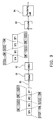
- FIG. 6 is a flowchart illustrating a multiplexing method for data switching according to an embodiment of the present invention.
- FIG. 7 is a circuit diagram of a soft bit puncturing unit using a data switching method of the present invention.
- FIG. 8 is a flowchart illustrating a data switching method according to an embodiment of the present invention.
- FIG. 9 is a circuit diagram of a multiplexing apparatus for data switching according to an embodiment of the present invention.
- FIG. 4 is a circuit diagram illustrating an application of data switching method of the present invention for unequal error protection according to an embodiment of the present invention.
- a continuous data is divided into four sequence codes SF 1 , SF 2 , SF 3 and SF 4 , wherein each of the sequence codes SF 1 ⁇ SF 4 represents for example, a super frame.
- Each of the sequence codes SF 1 ⁇ SF 4 includes a plurality of transmitting data S 1 , S 2 . . . SW, and each of the transmitting data S 1 ⁇ SW represents a frame.
- a soft bit puncturing unit 40 encodes each frame S 1 ⁇ SW and then punctures the each encoded frame to achieve an unequal error protection (UEP) effect, wherein each of the frames S 1 ⁇ SW requires a different bit error rate (BER). Assuming a relation of the BERs of the frames S 1 ⁇ SW within each of the super frames SF 1 ⁇ SF 4 is PS 1 >PS 2 . . . >PSW.
- the four super frames SF 1 ⁇ SF 4 are divided into a plurality of even super frames SF 2 and SF 4 and a plurality of odd super frames SF 1 and SF 3 .
- the frames S 1 ⁇ SW included in each odd super frame SF 1 and SF 3 are sorted by corresponding required BER of each frame decreasingly; and the frames S 1 ⁇ SW included in each even super frame SF 2 and SF 4 are sorted by the required BER of each frame increasingly.
- these sorted super frames are encoded and punctured by the soft bit puncturing unit 40 .
- the multiplexing method of the present invention is unnecessary for the multiplexing method of the present invention to add a string of bit codes padded with zeros to the tail of each of the frames S 1 ⁇ SW to satisfy a requirement of an encoder and puncturing tables, such that the waste of bandwidth can be avoided.
- utilization of a soft puncturing method by the soft bit puncturing unit 40 may avoid unexpected errors occurred due to excessive sudden changes of the BERs when performing decoding on the frames between two adjacent sequence codes (super frames) at a receiving terminal. Therefore, the multiplexing method of the present invention has a better error protection effect (i.e. may reduce the occurrence of errors) and a better transmitting efficiency (i.e. no waste of the bandwidth) than that of the conventional multiplexing method.
- FIG. 5 is a schematic diagram of bit error rates on a receiving terminal according to a multiplexing method of the present invention for data switching. Referring to FIG. 5 , the BERs of the frames SW and SW closely connected between two adjacent super frames are properly arranged, such that the unexpected errors occurred in an UEP system can be avoided, and the error protection efficiency of the UEP system is improved.
- each of the super frames includes a plurality of frames.
- super frames dividing step 61 by which the super frames are divided into a plurality of even super frames and a plurality of odd super frames.
- first sorting step 62 by which the frames included in each odd super frame are sorted by corresponding required BER of each frame decreasingly or increasingly.
- second sorting step 63 by which the frames included in each even super frame are sorted by the required BER of each frame increasingly or decreasingly.
- encoding step 64 by which an encoder is used to encode these sorted super frames.
- the frames included in each odd super frame are sorted by corresponding required BER of each frame decreasingly, the frames included in each even super frame are then sorted by the required BER of each frame increasingly in the second sorting step 63 . If the frames included in each odd super frame are sorted by corresponding required BER of each frame increasingly in the first sorting step 62 , the frames included in each super frame are then sorted by the required BER of each frame decreasingly in the second sorting step 63 .
- the BERs of the frames included in the super frames are not limited by sorting decreasingly first or increasingly first.
- the frames included in a super frame are sorted according to the required BER of each frame decreasingly, the frames included in the two adjacent super frames are then sorted according to the required BER of each frame increasingly. Conversely, if the frames included in the super frame are sorted according to the required BER of each frame increasingly, the frames included in the two adjacent super frames are then sorted according to the required BER of each frame decreasingly.
- the aforementioned multiplexing method may be applied to a plurality of systems requiring the UEP, for example, wireless LAN (WLAN), worldwide interoperability for microwave access (WiMAX), wideband code division multiple access (WCDMA), digital audio broadcast (DAB), digital video broadcasting (DVB) and real time multimedia network etc.
- WLAN wireless LAN
- WiMAX worldwide interoperability for microwave access
- WCDMA wideband code division multiple access
- DAB digital audio broadcast
- DVD digital video broadcasting
- FIG. 7 is a circuit diagram of a soft bit puncturing unit 40 according to an embodiment of the present invention.
- the soft bit puncturing unit 40 encodes and punctures the frames S 1 ⁇ SW requiring different BERs.
- the soft bit puncturing unit 40 includes an encoder 401 and a puncturing unit 402 coupled to the encoder 401 .
- the encoder 401 may be a common used encoder which is not limited by the present invention.
- the encoder 401 encodes the inputted frames S 1 ⁇ SW and generates an encoded data C_parent.
- the puncturing unit 402 provides corresponding puncturing tables T 1 , T 2 . . . TW to the inputted frames S 1 , S 2 . . .
- the puncturing unit 402 applies a soft switching method to improve a hamming weight of the encoded data punctured by the puncturing unit 402 , so as to improve the UEP efficiency. Owning to the utilization of the soft switching method by the puncturing unit 402 , not only is the UEP efficiency improved, but also waste of the bandwidth and poor transmission rate due to utilization of the conventional hard switching method which trying to achieve a better UEP effect can be avoided.
- the data switching method and apparatus thereof provided by the present invention may avoid the waste of the bandwidth and achieve a good UEP effect.
- the encoder 401 encodes the frames S 1 ⁇ SW and outputs the encoded data C_parent. Then, the puncturing unit 402 provides corresponding puncturing tables to the frames S 1 ⁇ SW requiring different BERs, and punctures the encoded data C_parent according to the puncturing tables to generate the punctured encoded data C_child.
- a conventional method of generating the punctured encoded data C_child according to the encoded data C_parent is as follows. Assuming the frame S 1 is provided, the encoder 401 encodes the frame S 1 and generates the encoded data C_parent. The puncturing unit 402 provides a puncturing table T 1 to the frame S 1 . Then, the puncturing unit 402 starts to puncture the encoded data C_parent according to the start position of the puncturing table T 1 and outputs the punctured encoded data C_child. During which if the bit code located at a certain position of the puncturing table T 1 is 1, the puncturing unit 402 then outputs the encoded data C_parent located in a position corresponding to that in the puncturing table T 1 .
- the puncturing unit 402 may sequentially provide the puncturing tables T 1 ⁇ TW to the corresponding frames S 1 ⁇ SW, wherein the relation of the puncturing tables T 1 ⁇ TW is described as follows. If the bit code located at a certain position of the puncturing table T 1 is 1, the bit codes located at the same positions of the puncturing tables T 2 ⁇ TW are also 1. If the bit code located at a certain position in the puncturing table T 2 is 1, the bit codes located at the same positions of the puncturing tables T 3 ⁇ TW are also 1. The relations of the other puncturing tables may be deduced accordingly.
- the bit code located at a first column and a second row of the puncturing table T 1 is 1, the bit code located at the first column and the second row of each of the puncturing tables T 2 ⁇ TW is also 1.
- the number of bits punctured in the frames S 1 ⁇ SW has a relation of S 1 >S 2 > . . . >SW.
- protection degrees of the frames S 1 ⁇ SW provided by the encoder 40 have an order of S 1 ⁇ S 2 ⁇ . . . ⁇ SW.
- the error correction ability provided by the encoder 40 may satisfy the requirement of different BERs for the frames S 1 ⁇ SW, such that the UEP can be achieved.
- the encoded data of the frame S 1 after being encoded by the encoder 401 is [1 0 1; 0 0 0]
- the corresponding puncturing table T 1 is [0 0 0 1 1; 1 0 1 1 1]
- the encoded data of the frame S 2 after being encoded by the encoder 401 is [1 1 1 0 1 1 1; 1 1 0 0 0 1 1]
- the corresponding puncturing table T 2 is [0 0 1 1 1; 1 0 1 1 1].
- the puncturing unit 402 starts to puncture the data located at 0 ⁇ 2 columns of the encoded data C_parent according to the start position of the puncturing table T 1 . Namely, 0 ⁇ 2 columns of the encoded data C_parent are punctured according to 0 ⁇ 2 columns of the puncturing table T 1 .
- the puncturing unit 402 records the third column of the puncturing table T 1 as a reference position of the puncturing table T 2 .
- the puncturing unit 402 then starts to puncture the data located at 3 ⁇ 9 columns of the encoded data C_parent according to the reference position of the puncturing table T 2 .
- the 3 ⁇ 9 columns of the encoded data C_parent include more columns than that included in the puncturing table T 2 . Therefore, the puncturing process is also started according to the reference position of the puncturing table T 2 , until the end position of the puncturing table T 2 . In this case, some bits of the encoded data C_parent will be left un-punctured. Then, the puncturing process is restarted according to the start position of the puncturing table T 2 until puncturing of the C_parent is completed.
- the puncturing unit 402 starts to puncture the data located at 0 ⁇ 4 columns of the encoded data C_parent according to the start position of the puncturing table T 1 . Namely, 0 ⁇ 4 columns of the encoded data C_parent are punctured according to 0 ⁇ 4 columns of the puncturing table T 1 . Then, the puncturing unit 402 records the start position of the puncturing table T 2 as the reference position of the puncturing table T 2 . The puncturing unit 402 then punctures the data located at 5 ⁇ 11 columns of the encoded data C_parent according to the reference position of the puncturing table T 2 . However, the 5 ⁇ 11 columns of the encoded data C_parent include more columns than that included in the puncturing table T 2 .
- the puncturing process is also started according to the reference position of the puncturing table T 2 , until the end position of the puncturing table T 2 .
- some bits of the encoded data C_parent will be left un-punctured.
- the puncturing process is restarted according to the start position of the puncturing table T 2 until puncturing of the C_parent is completed.
- the puncturing unit 402 first punctures the data located at 5 ⁇ 9 columns of the encoded data C_parent according to the data located at 0 ⁇ 4 columns of the puncturing table T 2 .
- the puncturing unit 402 records the second column of the puncturing table T 2 as the reference position of the puncturing table T 3 .
- the puncturing unit 402 punctures the data located at 12 ⁇ 16 columns of the encoded data C_parent according to the reference position of the puncturing table T 3 .
- the puncturing process is also started according to the reference position of the puncturing table T 3 , until the end position of the puncturing table T 3 . In this case, some bits of the encoded data C_parent will be left un-punctured.
- the puncturing process is restarted according to the start position of the puncturing table T 3 until puncturing of the C_parent is completed.
- the puncturing unit 402 first punctures the data located at 12 ⁇ 14 columns of the encoded data C_parent according to the data located at 2 ⁇ 4 columns of the puncturing table T 3 .
- the data located at 15 ⁇ 16 columns of the encoded data C_parent are punctured according to the data located at 0 ⁇ 1 columns of the puncturing table T 3 .
- the algorithm of the soft switching method may be represented by:
- tk represents the end position of a (k ⁇ 1)-th puncturing table plus 1.
- T ij (k) represents the bit code located at i-th row and j-th column in a k-th puncturing table, and the number of the total columns of the k-th puncturing table is p.
- tk′ represents a k-th frame is ended on a tk′-th column of the C_parent.
- C_parent i,t represents the encoded data located at the i-th row and t-th colomn.
- bit code located at the i-th row and (t mod p)-th column of the puncturing table is 1, data located at i-th row and t-th column of the encoded data C_parent can be transmitted. If the bit code located at the i-th row and (t mod p)-th column of the puncturing table is 0, data located at i-th row and t-th column of the encoded data C_parent is punctured.
- FIG. 8 is a flowchart illustrating a data switching method according to an embodiment of the present invention.
- the encoding step 80 by which a plurality of frames is encoded by the encoder 401 .
- the first initialization step 81 by which a plurality of puncturing tables are provided, and the start position and the end position of each puncturing table are recorded for processing the corresponding encoded frame, wherein each puncturing table includes a plurality of bit codes.
- the second initialization step 82 by which the start position of the first puncturing table is recorded as the reference position of the first puncturing table.
- the puncturing step 83 by which the k-th frame is punctured according to the k-th puncturing table, and the puncturing process is started according to the reference position of the k-th puncturing table until the end position of the k-th puncturing table, and if there are still some bits of the k-th frame left un-punctured, the puncturing process is restarted according to the start position of the k-th puncturing table until puncturing of the k-th frame is completed.
- Fifth, recording step 84 by which the reference position of the (k+1)-th puncturing table is recorded, and when puncturing process of the k-th frame is completed, the present position of the k-th puncturing table is judged whether to be the end position of the k-th puncturing table or not. If not, the position of the bit code in the puncturing table where puncturing of the k-th frame being completed plus 1 is recorded as the reference position of the (k+1)-th puncturing table. If yes, the start position of the (k+1)-th puncturing table is recorded as the reference position of the (k+1)-th puncturing table.
- the above puncturing step 83 and recording step 84 are repeatedly performed until puncturing of the frames is completed.
- the last step is outputting step 85 , by which the punctured encoded data is outputted.
- the encoder 401 used in the encoding step 80 of the above-described data switching method may be a convolution code encoder, a turbo code encoder or a low-density parity-check (LDPC) encoder.
- the puncturing tables of the above-described data switching method can be stored in a memory device, which may be a non-volatile memory device. For example, read only memory (ROM) or flash etc.
- the second frame may be a data having more significance than that of the first frame.
- the first frame may be a motion imaging vector data
- the second frame may be a static image data.
- the first frame may be a plurality of data having the least significant bits (LSB) in an image data
- the second frame may be a plurality of data having the most significant bits (MSB) in an image data.
- the first frame may be the audio data
- the second frame may be the image data.
- FIG. 9 is a circuit diagram of a multiplexing apparatus for data switching according to an embodiment of the present invention.
- the multiplexing apparatus includes an input terminal 90 , a divider 91 , an arbiter 92 and an encoder 93 .
- the divider 91 is coupled to the input terminal 90
- the arbiter 92 is coupled to the divider 91
- the encoder 93 is coupled to the arbiter 92 .
- the input terminal is used for inputting a continuous data including the plurality of super frames SF 1 ⁇ SF 4 , wherein each of the super frames SF 1 ⁇ SF 4 includes a plurality of frames S 1 ⁇ SW.
- the relation of the BERs required by the frames S 1 ⁇ SW is PS 1 >PS 2 > . . . >PSW.
- the divider 91 is used for dividing the plurality of super frames into a plurality of odd super frames SF 1 , SF 3 and a plurality of even super frames SF 2 , SF 4 .
- the frames S 1 ⁇ SW included in each odd super frame SF 1 and SF 3 are sorted by the arbiter 92 according to the corresponding required BER of each frame decreasingly.
- the frames S 1 ⁇ SW included in each even super frame SF 2 and SF 4 are sorted by the arbiter 92 according to the required BER of each frame increasingly (the sorting result is shown as an output of the arbiter 92 in FIG. 9 ).
- the encoder 93 is then used to encode these sorted super frames SF 1 ⁇ SFW.
- the sorting method of the arbiter 92 may also be as follows.
- the frames S 1 ⁇ SW included in each odd super frame SF 1 and SF 3 are sorted according to the required BER of each frame increasingly, and the frames S 1 ⁇ SW included in each even super frame SF 2 and SF 4 are sorted according to the required BER of each frame decreasingly.
- sorting of the frames included each odd super frames is not limited by sorting the required BER of each frame decreasingly first or increasingly first.
- the multiplexing apparatus further includes a puncturing unit 94 coupled to the encoder 93 .
- the puncturing unit 94 is used for puncturing the encoded frames and recording positions.
- the puncturing unit 94 further includes a plurality of puncturing tables providing the start and end positions for the puncturing unit 94 to record.
- the puncturing unit 94 punctures the encoded frames according to the puncturing tables.
- Each of the puncturing tables includes a plurality of the bit codes.
- the puncturing unit 94 may record the start position of the first puncturing table as the reference position of the first puncturing table.
- the puncturing unit 94 may puncture the k-th frame according to the k-th puncturing table, and puncturing of the k-th frame is started according to the reference position of the k-th puncturing table until the end position of the k-th puncturing table, and if there are still some bits of the k-th frame left un-punctured, the puncturing process is restarted according to the start position of the k-th puncturing table until puncturing of the k-th frame is completed.
- the puncturing unit 94 judges whether the present position of the k-th puncturing table is the end position of the k-th puncturing table or not.
- the puncturing unit 94 outputs the punctured encoded data.
- the aforementioned multiplexing apparatus for data switching may be applied to a plurality of communication standards and network systems, for example, WLAN, WiMAX, WCDMA, DAB, DVB and real time multimedia network etc.
- the encoder 93 used in the aforementioned multiplexing apparatus may be a convolution code encoder, a turbo code encoder or a LDPC encoder.
- the puncturing tables of the aforementioned multiplexing apparatus can be stored in a memory device, which may be a non-volatile memory device. For example, ROM or flash etc.
- application of the data multiplexing method and apparatus of the present invention has the following advantages.
- Great variation of the BERs of the frames located between two adjacent super frames is avoided, and therefore unexpected errors occurred in the system is mitigated.
- the rate-compatible punctured code encoder applying the soft switching method may avoid the problem of excessive decrease of hamming weight which usually happens when the conventional hard switching method is applied, such that a better UEP effect is achieve.
Landscapes
- Engineering & Computer Science (AREA)
- Physics & Mathematics (AREA)
- Probability & Statistics with Applications (AREA)
- Theoretical Computer Science (AREA)
- Computer Networks & Wireless Communication (AREA)
- Signal Processing (AREA)
- Detection And Prevention Of Errors In Transmission (AREA)
Abstract
Description
Claims (17)
Applications Claiming Priority (3)
| Application Number | Priority Date | Filing Date | Title |
|---|---|---|---|
| TW096125018A TWI362855B (en) | 2007-07-10 | 2007-07-10 | Multiplexing method and apparatus thereof for data switching |
| TW96125018 | 2007-07-10 | ||
| TW96125018A | 2007-07-10 |
Publications (2)
| Publication Number | Publication Date |
|---|---|
| US20090016352A1 US20090016352A1 (en) | 2009-01-15 |
| US8060796B2 true US8060796B2 (en) | 2011-11-15 |
Family
ID=40253054
Family Applications (1)
| Application Number | Title | Priority Date | Filing Date |
|---|---|---|---|
| US11/864,992 Active 2030-09-14 US8060796B2 (en) | 2007-07-10 | 2007-09-29 | Multiplexing method and apparatus thereof for data switching |
Country Status (2)
| Country | Link |
|---|---|
| US (1) | US8060796B2 (en) |
| TW (1) | TWI362855B (en) |
Cited By (4)
| Publication number | Priority date | Publication date | Assignee | Title |
|---|---|---|---|---|
| US20100275089A1 (en) * | 2009-04-27 | 2010-10-28 | The Hong Kong University Of Science And Technology | Iterative decoding of punctured low-density parity check codes by selection of decoding matrices |
| US20130080864A1 (en) * | 2007-11-21 | 2013-03-28 | Micron Technology, Inc. | Memory controller supporting rate-compatible punctured codes |
| RU2612605C1 (en) * | 2013-02-15 | 2017-03-09 | ЭлДжи ЭЛЕКТРОНИКС ИНК. | Method and device for transmitting/receiving frame in accordance with its bandwidth in wlan |
| US20190260390A1 (en) * | 2016-11-03 | 2019-08-22 | Huawei Technologies Co., Ltd. | Method and apparatus for encoding and decoding ldpc codes |
Families Citing this family (2)
| Publication number | Priority date | Publication date | Assignee | Title |
|---|---|---|---|---|
| CN106452678B (en) * | 2016-10-21 | 2017-07-21 | 郑州大学西亚斯国际学院 | A kind of Turbo code puncturing method being distributed based on bit error rate |
| US10841841B2 (en) * | 2018-09-17 | 2020-11-17 | Cisco Technology, Inc. | Using wireless channel variance values in order to improve application quality of experience (QoE) in wireless communication systems |
Citations (8)
| Publication number | Priority date | Publication date | Assignee | Title |
|---|---|---|---|---|
| US5883899A (en) * | 1995-05-01 | 1999-03-16 | Telefonaktiebolaget Lm Ericsson | Code-rate increased compressed mode DS-CDMA systems and methods |
| US6158041A (en) * | 1998-10-14 | 2000-12-05 | Cisco Technology | System and method for I/Q trellis coded modulation |
| US6233713B1 (en) * | 1998-08-24 | 2001-05-15 | Institute Of Microelectronics | Method and apparatus for real-time determination of scalable channel coding scheme parameters |
| US6275480B1 (en) * | 1997-09-12 | 2001-08-14 | Lockheed Martin Corp. | Fast associated control channel coding for speech channel |
| US6622281B1 (en) * | 1999-07-14 | 2003-09-16 | Lg Information & Communications, Ltd. | Rate matching method in mobile communication system |
| US7027518B2 (en) * | 2000-10-31 | 2006-04-11 | Nokia Mobile Phones, Ltd. | Method and arrangement for providing optimal bit protection against transmission errors |
| US7404138B2 (en) * | 2000-06-12 | 2008-07-22 | Samsung Electronics Co., Ltd | Apparatus and method for encoding and decoding TFCI in a mobile communication system |
| US7778197B2 (en) * | 2005-12-08 | 2010-08-17 | Lg Electronics Inc. | Mobile communications terminal for supporting space-time hybrid automatic repeat request techniques and method thereof |
-
2007
- 2007-07-10 TW TW096125018A patent/TWI362855B/en active
- 2007-09-29 US US11/864,992 patent/US8060796B2/en active Active
Patent Citations (8)
| Publication number | Priority date | Publication date | Assignee | Title |
|---|---|---|---|---|
| US5883899A (en) * | 1995-05-01 | 1999-03-16 | Telefonaktiebolaget Lm Ericsson | Code-rate increased compressed mode DS-CDMA systems and methods |
| US6275480B1 (en) * | 1997-09-12 | 2001-08-14 | Lockheed Martin Corp. | Fast associated control channel coding for speech channel |
| US6233713B1 (en) * | 1998-08-24 | 2001-05-15 | Institute Of Microelectronics | Method and apparatus for real-time determination of scalable channel coding scheme parameters |
| US6158041A (en) * | 1998-10-14 | 2000-12-05 | Cisco Technology | System and method for I/Q trellis coded modulation |
| US6622281B1 (en) * | 1999-07-14 | 2003-09-16 | Lg Information & Communications, Ltd. | Rate matching method in mobile communication system |
| US7404138B2 (en) * | 2000-06-12 | 2008-07-22 | Samsung Electronics Co., Ltd | Apparatus and method for encoding and decoding TFCI in a mobile communication system |
| US7027518B2 (en) * | 2000-10-31 | 2006-04-11 | Nokia Mobile Phones, Ltd. | Method and arrangement for providing optimal bit protection against transmission errors |
| US7778197B2 (en) * | 2005-12-08 | 2010-08-17 | Lg Electronics Inc. | Mobile communications terminal for supporting space-time hybrid automatic repeat request techniques and method thereof |
Cited By (11)
| Publication number | Priority date | Publication date | Assignee | Title |
|---|---|---|---|---|
| US20130080864A1 (en) * | 2007-11-21 | 2013-03-28 | Micron Technology, Inc. | Memory controller supporting rate-compatible punctured codes |
| US8966352B2 (en) * | 2007-11-21 | 2015-02-24 | Micron Technology, Inc. | Memory controller supporting rate-compatible punctured codes and supporting block codes |
| US9442796B2 (en) | 2007-11-21 | 2016-09-13 | Micron Technology, Inc. | Memory controller supporting rate-compatible punctured codes |
| US20100275089A1 (en) * | 2009-04-27 | 2010-10-28 | The Hong Kong University Of Science And Technology | Iterative decoding of punctured low-density parity check codes by selection of decoding matrices |
| US8245097B2 (en) * | 2009-04-27 | 2012-08-14 | Kan Ling Capital, L.L.C. | Iterative decoding of punctured low-density parity check codes by selection of decoding matrices |
| RU2612605C1 (en) * | 2013-02-15 | 2017-03-09 | ЭлДжи ЭЛЕКТРОНИКС ИНК. | Method and device for transmitting/receiving frame in accordance with its bandwidth in wlan |
| US9775174B2 (en) | 2013-02-15 | 2017-09-26 | Lg Electronics Inc. | Method and device for transmitting/receiving frame in accordance with bandwidth thereof in WLAN system |
| US9918342B2 (en) | 2013-02-15 | 2018-03-13 | Lg Electronics Inc. | Method and device for transmitting/receiving frame in accordance with bandwidth thereof in WLAN system |
| US20190260390A1 (en) * | 2016-11-03 | 2019-08-22 | Huawei Technologies Co., Ltd. | Method and apparatus for encoding and decoding ldpc codes |
| US10567002B2 (en) * | 2016-11-03 | 2020-02-18 | Huawei Technologies Co., Ltd. | Method and apparatus for encoding and decoding LDPC codes |
| US11265014B2 (en) | 2016-11-03 | 2022-03-01 | Huawei Technologies Co., Ltd. | Method and apparatus for encoding and decoding LDPC codes |
Also Published As
| Publication number | Publication date |
|---|---|
| US20090016352A1 (en) | 2009-01-15 |
| TWI362855B (en) | 2012-04-21 |
| TW200904055A (en) | 2009-01-16 |
Similar Documents
| Publication | Publication Date | Title |
|---|---|---|
| EP2201691B1 (en) | Scalable information signal, apparatus and method for encoding a scalable information content, and apparatus and method for error correcting a scalable information signal | |
| Sejdinovic et al. | Expanding window fountain codes for unequal error protection | |
| US8060796B2 (en) | Multiplexing method and apparatus thereof for data switching | |
| US8046658B2 (en) | Method and device for decoding blocks encoded with an LDPC code | |
| MXPA05005308A (en) | Rate-compatible low-density parity-check (ldpc) codes. | |
| US11438097B2 (en) | Media content-based adaptive method, device and system for forward error correction (FEC) coding and decoding of systematic code, and medium | |
| KR100669152B1 (en) | Apparatus and method for coding of low density parity check code | |
| JP2021502767A (en) | Decoding method of stair code, device and storage medium | |
| JP5497917B2 (en) | Orthogonal multiple description coding | |
| US8201030B2 (en) | Method and apparatus for parallel structured Latin square interleaving in communication system | |
| US20070250760A1 (en) | Extended Convolutional Codes | |
| CN112534724B (en) | Decoder and method for decoding polarization code and product code | |
| US8402340B2 (en) | Parity-check-code decoder and recording controller | |
| CN113114427B (en) | Self-adaptive system code FEC encoding method and decoding method based on media content | |
| CN113472362A (en) | Coding method and device for data communication | |
| WO2023060865A1 (en) | Encoding method and device, and decoding method and device | |
| CN101359977B (en) | Method and apparatus suitable for data switching multiplexing | |
| Pu et al. | Unequal error protection and progressive decoding for jpeg2000 | |
| CN106656408B (en) | Decoding method and device based on check matrix | |
| AU2022332699A1 (en) | Modified staircase forward error correction coding | |
| RU2541844C1 (en) | Method of decoding production code using weight ordered adjacent class of error vectors and apparatus therefor | |
| CN101807928A (en) | Recording controller and parity check code decoder |
Legal Events
| Date | Code | Title | Description |
|---|---|---|---|
| AS | Assignment |
Owner name: INDUSTRIAL TECHNOLOGY RESEARCH INSTITUTE, TAIWAN Free format text: ASSIGNMENT OF ASSIGNORS INTEREST;ASSIGNORS:WANG, CHUNG-HSUAN;LEE, SHUENN-GI;REEL/FRAME:019971/0410;SIGNING DATES FROM 20070829 TO 20070903 Owner name: NATIONAL CHIAO TUNG UNIVERSITY, TAIWAN Free format text: ASSIGNMENT OF ASSIGNORS INTEREST;ASSIGNORS:WANG, CHUNG-HSUAN;LEE, SHUENN-GI;REEL/FRAME:019971/0410;SIGNING DATES FROM 20070829 TO 20070903 Owner name: INDUSTRIAL TECHNOLOGY RESEARCH INSTITUTE, TAIWAN Free format text: ASSIGNMENT OF ASSIGNORS INTEREST;ASSIGNORS:WANG, CHUNG-HSUAN;LEE, SHUENN-GI;SIGNING DATES FROM 20070829 TO 20070903;REEL/FRAME:019971/0410 Owner name: NATIONAL CHIAO TUNG UNIVERSITY, TAIWAN Free format text: ASSIGNMENT OF ASSIGNORS INTEREST;ASSIGNORS:WANG, CHUNG-HSUAN;LEE, SHUENN-GI;SIGNING DATES FROM 20070829 TO 20070903;REEL/FRAME:019971/0410 |
|
| STCF | Information on status: patent grant |
Free format text: PATENTED CASE |
|
| CC | Certificate of correction | ||
| FPAY | Fee payment |
Year of fee payment: 4 |
|
| MAFP | Maintenance fee payment |
Free format text: PAYMENT OF MAINTENANCE FEE, 8TH YEAR, LARGE ENTITY (ORIGINAL EVENT CODE: M1552); ENTITY STATUS OF PATENT OWNER: LARGE ENTITY Year of fee payment: 8 |
|
| MAFP | Maintenance fee payment |
Free format text: PAYMENT OF MAINTENANCE FEE, 12TH YEAR, LARGE ENTITY (ORIGINAL EVENT CODE: M1553); ENTITY STATUS OF PATENT OWNER: LARGE ENTITY Year of fee payment: 12 |