US8054643B2 - Semiconductor module, wiring board, and wiring method - Google Patents
Semiconductor module, wiring board, and wiring method Download PDFInfo
- Publication number
- US8054643B2 US8054643B2 US12/320,641 US32064109A US8054643B2 US 8054643 B2 US8054643 B2 US 8054643B2 US 32064109 A US32064109 A US 32064109A US 8054643 B2 US8054643 B2 US 8054643B2
- Authority
- US
- United States
- Prior art keywords
- semiconductor devices
- wiring
- rows
- semiconductor
- wiring board
- Prior art date
- Legal status (The legal status is an assumption and is not a legal conclusion. Google has not performed a legal analysis and makes no representation as to the accuracy of the status listed.)
- Expired - Fee Related, expires
Links
Images


Classifications
-
- H—ELECTRICITY
- H05—ELECTRIC TECHNIQUES NOT OTHERWISE PROVIDED FOR
- H05K—PRINTED CIRCUITS; CASINGS OR CONSTRUCTIONAL DETAILS OF ELECTRIC APPARATUS; MANUFACTURE OF ASSEMBLAGES OF ELECTRICAL COMPONENTS
- H05K1/00—Printed circuits
- H05K1/18—Printed circuits structurally associated with non-printed electric components
- H05K1/181—Printed circuits structurally associated with non-printed electric components associated with surface mounted components
-
- H—ELECTRICITY
- H05—ELECTRIC TECHNIQUES NOT OTHERWISE PROVIDED FOR
- H05K—PRINTED CIRCUITS; CASINGS OR CONSTRUCTIONAL DETAILS OF ELECTRIC APPARATUS; MANUFACTURE OF ASSEMBLAGES OF ELECTRICAL COMPONENTS
- H05K2201/00—Indexing scheme relating to printed circuits covered by H05K1/00
- H05K2201/09—Shape and layout
- H05K2201/09209—Shape and layout details of conductors
- H05K2201/09218—Conductive traces
- H05K2201/09245—Crossing layout
-
- H—ELECTRICITY
- H05—ELECTRIC TECHNIQUES NOT OTHERWISE PROVIDED FOR
- H05K—PRINTED CIRCUITS; CASINGS OR CONSTRUCTIONAL DETAILS OF ELECTRIC APPARATUS; MANUFACTURE OF ASSEMBLAGES OF ELECTRICAL COMPONENTS
- H05K2201/00—Indexing scheme relating to printed circuits covered by H05K1/00
- H05K2201/09—Shape and layout
- H05K2201/09209—Shape and layout details of conductors
- H05K2201/09654—Shape and layout details of conductors covering at least two types of conductors provided for in H05K2201/09218 - H05K2201/095
- H05K2201/097—Alternating conductors, e.g. alternating different shaped pads, twisted pairs; Alternating components
-
- H—ELECTRICITY
- H05—ELECTRIC TECHNIQUES NOT OTHERWISE PROVIDED FOR
- H05K—PRINTED CIRCUITS; CASINGS OR CONSTRUCTIONAL DETAILS OF ELECTRIC APPARATUS; MANUFACTURE OF ASSEMBLAGES OF ELECTRICAL COMPONENTS
- H05K2201/00—Indexing scheme relating to printed circuits covered by H05K1/00
- H05K2201/10—Details of components or other objects attached to or integrated in a printed circuit board
- H05K2201/10007—Types of components
- H05K2201/10159—Memory
-
- H—ELECTRICITY
- H05—ELECTRIC TECHNIQUES NOT OTHERWISE PROVIDED FOR
- H05K—PRINTED CIRCUITS; CASINGS OR CONSTRUCTIONAL DETAILS OF ELECTRIC APPARATUS; MANUFACTURE OF ASSEMBLAGES OF ELECTRICAL COMPONENTS
- H05K2201/00—Indexing scheme relating to printed circuits covered by H05K1/00
- H05K2201/10—Details of components or other objects attached to or integrated in a printed circuit board
- H05K2201/10613—Details of electrical connections of non-printed components, e.g. special leads
- H05K2201/10621—Components characterised by their electrical contacts
- H05K2201/10689—Leaded Integrated Circuit [IC] package, e.g. dual-in-line [DIL]
-
- Y—GENERAL TAGGING OF NEW TECHNOLOGICAL DEVELOPMENTS; GENERAL TAGGING OF CROSS-SECTIONAL TECHNOLOGIES SPANNING OVER SEVERAL SECTIONS OF THE IPC; TECHNICAL SUBJECTS COVERED BY FORMER USPC CROSS-REFERENCE ART COLLECTIONS [XRACs] AND DIGESTS
- Y02—TECHNOLOGIES OR APPLICATIONS FOR MITIGATION OR ADAPTATION AGAINST CLIMATE CHANGE
- Y02P—CLIMATE CHANGE MITIGATION TECHNOLOGIES IN THE PRODUCTION OR PROCESSING OF GOODS
- Y02P70/00—Climate change mitigation technologies in the production process for final industrial or consumer products
- Y02P70/50—Manufacturing or production processes characterised by the final manufactured product
-
- Y—GENERAL TAGGING OF NEW TECHNOLOGICAL DEVELOPMENTS; GENERAL TAGGING OF CROSS-SECTIONAL TECHNOLOGIES SPANNING OVER SEVERAL SECTIONS OF THE IPC; TECHNICAL SUBJECTS COVERED BY FORMER USPC CROSS-REFERENCE ART COLLECTIONS [XRACs] AND DIGESTS
- Y10—TECHNICAL SUBJECTS COVERED BY FORMER USPC
- Y10T—TECHNICAL SUBJECTS COVERED BY FORMER US CLASSIFICATION
- Y10T29/00—Metal working
- Y10T29/49—Method of mechanical manufacture
- Y10T29/49002—Electrical device making
- Y10T29/49117—Conductor or circuit manufacturing
- Y10T29/49124—On flat or curved insulated base, e.g., printed circuit, etc.
- Y10T29/4913—Assembling to base an electrical component, e.g., capacitor, etc.
Definitions
- the present invention relates to a semiconductor module having a plurality of mutually electrically connected semiconductor devices arranged on a wiring board, and in particular to a wiring board and a wiring method for such a semiconductor module.
- One of measures proposed to avoid this problem is a method of arranging a plurality of semiconductor devices alternately lengthwise and crosswise while changing alternately their orientations by 90 degrees.
- Patent Document 1 Japanese Patent Laid-Open Publication No. H11-163531 (Patent Document 1), No. 2000-082743 (Patent Document 2), No. 2004-096095 (Patent Document 3), and No. H11-340438 (Patent Document 4)).
- a plurality of signal wiring lines included in a signal wiring group connecting between semiconductor devices are required to have equal lengths in order to uniform their electrical characteristics to minimize signal-to-signal skew.
- a signal wiring group of wiring lines connecting between the semiconductor devices must be laid out in a meander shape according to arrangement of pads of the semiconductor devices due to limitations of a wiring region. Consequently, some of the signal wiring lines necessarily take a longer way while some take a shorter way, making it difficult to equalize the lengths of the signal wiring lines.
- the present inventor has recognized that the skew (delay time difference) between the signal wiring lines is increased and that the high-speed operation required for the semiconductor devices cannot be achieved.
- the present invention seeks to provide a semiconductor module in which each pair of adjacent semiconductor devices is arranged in orientations differed by 90 degrees from each other, the semiconductor device being mutually connected by means of a plurality of signal wiring lines having substantially equal lengths, whereby signal-to-signal skew is reduced.
- Patent Documents 1 to 4 discusses a semiconductor module having each pair of adjacent semiconductor devices arranged in orientations differed by 90 degrees from each other, and none of these patent documents discloses or suggests a technique to equalize the lengths of wiring lines in such a semiconductor module.
- none of Patents Documents 1 to 4 discloses or suggests at all that a plurality of semiconductor devices are arranged in two rows and via holes positioned in the vicinity of the semiconductor devices belonging to one of the rows and via holes positioned in the vicinity of the semiconductor devices belonging to the other row are connected by means of signal wiring lines in staggered manner (the signal wiring lines are laid out in a cross stitch like pattern).
- a semiconductor module that includes a plurality of rectangular-shaped semiconductor devices arranged in two rows such that each pair of adjacent semiconductor devices is in orientations differed by 90 degrees from each other.
- a plurality of wiring lines connect the semiconductor devices included in one of the two rows to the semiconductor devices included in the other row such that the semiconductor devices arranged in the same orientations are connected to each other.
- the configuration of the semiconductor module makes it possible to form a plurality of signal wiring lines connecting one semiconductor device to another to have substantially equal lengths, and hence to reduce the signal-to-signal skew.
- FIG. 1 is a schematic diagram showing a wiring pattern of a related semiconductor module
- FIG. 2 is a detail diagram showing details of the wiring pattern of FIG. 1 ;
- FIG. 3 is a conceptual diagram showing a semiconductor module according to a first embodiment of the present invention.
- FIGS. 4A and 4B are diagrams for explaining relationships between via hole groups and signal wiring line groups in the semiconductor module of FIG. 3 ;
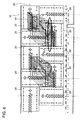
- FIG. 5 is a schematic diagram showing an example of a wiring pattern in a wiring layer forming a wiring board used in the semiconductor module of FIG. 3 ;
- FIG. 6 is a detail diagram showing details of the wiring pattern of FIG. 5 ;
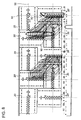
- FIG. 7 is a schematic diagram showing an example of a wiring pattern in another wiring layer forming the wiring board used in the semiconductor module of FIG. 3 ;
- FIG. 8 is a detail diagram showing details of the wiring pattern of FIG. 7 ;
- FIG. 9 is a schematic diagram showing an example of a wiring pattern in still another wiring layer forming the wiring board used in the semiconductor module of FIG. 3 ;
- FIG. 10 is a detail diagram showing details of the wiring pattern of FIG. 9 ;
- FIG. 11 is a schematic diagram showing an example of a wiring pattern in still another wiring layer forming the wiring board used in the semiconductor module of FIG. 3 ;
- FIG. 12 is a detail diagram showing details of the wiring pattern of FIG. 11 .
- FIGS. 1 and 2 Before describing of the present invention, a related semiconductor module will be explained in detail with reference to FIGS. 1 and 2 in order to facilitate the understanding of the present invention.
- FIGS. 1 and 2 are plan views showing the related semiconductor module.
- FIG. 1 is a simplified schematic diagram of the semiconductor module. As illustrated in FIG. 1 , the semiconductor module has a plurality of semiconductor devices 20 provided on a wiring board 200 .
- FIG. 2 is a wiring pattern diagram corresponding to FIG. 1 , showing a representation closer to a product image. In FIG. 2 , exposed via holes are depicted by solid line double circles while embedded via holes are depicted by broken line double circles. The same holds true for FIGS. 6 , 8 , 10 and 12 .
- each of the semiconductor devices 20 is electrically connected to another and adjacent semiconductor device 20 via a signal wiring group 11 and a via hole group 40 provided on the wiring board 200 .
- the wiring board 200 is provided for example by a multilayer wiring board.
- the semiconductor devices 20 may be semiconductor memory devices such as DRAMs or semiconductor integrated circuit devices such as system LSIs.
- FIG. 3 is a conceptual diagram of a semiconductor module according to a first embodiment of the present invention.
- the shown semiconductor module has a wiring board 100 and a plurality of semiconductor devices 20 , 20 ′ mounted thereon.
- the wiring board 100 has via hole groups 40 , 40 ′ to which the semiconductor devices 20 , 20 ′ are connected, and signal wiring groups (or wirings) 10 , 10 ′ connecting via holes included in these via hole groups 40 , 40 ′.
- the semiconductor devices 20 and the semiconductor devices 20 ′ have the same configuration.
- the semiconductor devices 20 , 20 ′ are each provided with an index mark (a mark indicating an orientation of the semiconductor device) not shown in the drawing.
- the semiconductor devices 20 are arranged such that their index marks all point to the same direction, for example upwards, as viewed in the drawing.
- the semiconductor devices 20 ′ are also arranged such that their index marks all point to the same direction, for example to the right-hand side, as viewed in the drawing.
- the semiconductor devices 20 ′ are arranged in an orientation differed, or rotated by 90 degrees relative to the semiconductor devices 20 arranged in one orientation.
- the semiconductor devices 20 and the semiconductor devices 20 ′ are thus arranged alternately in two rows.
- the wiring board 100 has a region in which a plurality of rectangular-shaped semiconductor devices 20 , 20 ′ are arranged in two rows such that each pair of adjacent semiconductor devices is arranged in different orientations differed by 90 degrees from each other.
- the via hole groups 40 , 40 ′ are provided corresponding to the semiconductor devices 20 , 20 ′, respectively. Each of the semiconductor devices 20 , 20 ′ is electrically connected to a via hole group 40 or 40 ′ provided in the vicinity thereof when mounted on the wiring board 100 .
- Wiring lines included in each signal wiring group 10 are connected to via holes included in the via hole groups 40 provided in the vicinity of the semiconductor devices 20 .
- wiring lines included in each signal wiring group 10 ′ are connected to via holes included in the via hole groups 40 ′ provided in the vicinity of the semiconductor devices 20 ′.
- the signal wiring groups 10 connect, in a zigzag manner, the via hole groups 40 corresponding to the semiconductor devices 20 in one of the rows (the upper row as viewed in the drawing) and the via hole groups 40 corresponding to the semiconductor devices 20 in the other row (the lower row as viewed in the drawing).
- the signal wiring groups 10 ′ connect, in a zigzag manner, the via hole groups 40 ′ corresponding to the semiconductor devices 20 ′ in one of the rows (the upper row as viewed in the drawing) and the via hole groups 40 ′ corresponding to the semiconductor device 20 ′ in the other row (the lower row as viewed in the drawing).
- FIGS. 4A and 4B are diagrams for explaining the relationships between the via hole groups 40 and the signal wiring groups 10 in FIG. 3 .
- FIG. 4A shows the case in which when additional lines 50 are drawn, passing through the centers of the via hole groups 40 , 40 ′, a region 51 surrounded by four additional lines 50 assumes a rectangular shape.
- a plurality of (three herein) via holes included in each via hole group 40 are arranged along a longitudinal direction of the wiring board 100 (crosswise direction in the drawing).
- a plurality of wiring lines included in the signal wiring groups 10 connected by these via holes are parallel to the diagonal lines of the region 51 and have equal lengths.
- a plurality of (three herein) via holes included in each via hole group 40 ′ are arranged perpendicularly to a longitudinal direction of the wiring board 100 (crosswise direction in the drawing).
- a plurality of wiring lines included in the signal wiring groups 10 ′ connected by these via holes are also parallel to the diagonal lines of the region 51 and have equal lengths. This makes it possible to prevent the occurrence of signal-to-signal skew in two semiconductor devices connected by these signal wiring groups 10 or 10 ′.
- the lengths of the wiring lines of the signal wiring groups 10 connected to the via holes included in the via hole groups 40 are equal to the lengths of the wiring lines of the signal wiring groups 10 ′ connected to the via holes included in the via hole groups 40 ′. Therefore, the wiring lines extending from the upper row to the lower row are of equal lengths, while the wiring lines extending from the lower row to the upper row are also of equal lengths.
- FIG. 4B shows the case in which when additional lines 50 are drawn passing through the centers of the via hole groups 40 , 40 ′, a region 51 surrounded by four additional lines assumes a trapezoidal shape.
- the lengths of the signal wiring lines extending from the upper row to the lower row are equal to the lengths of the signal wiring lines extending from the lower row to the upper row.
- the lengths of the signal wiring lines extending from the upper row to the lower row are equal to the lengths of the signal wiring lines extending from the lower row to the upper row, as long as the region 51 surrounded by the additional lines 50 is symmetric relative to a center line 52 thereof.
- the wiring lines can be laid in equal lengths without producing wiring lines taking a longer way or wiring lines taking a shorter way. As a result, the signal-to-signal skew can be reduced.
- the wiring board 100 will be described in further detail.
- the wiring board 100 can be provided by using a multilayer wiring board.
- a multilayer wiring board has wiring layers having wiring patterns, for example, as shown in FIGS. 5 and 6 .
- FIG. 5 is a simplified schematic diagram showing an example of a wiring pattern
- FIG. 6 is a wiring pattern diagram corresponding to the wiring pattern of FIG. 5 , showing a representation closer to a product image.
- the semiconductor devices 20 and the semiconductor devices 20 ′ are arranged on the wiring board 100 in different orientations, differed by 90 degrees, as described in the above with reference to FIG. 3 .
- a plurality of via holes included in the via hole groups 40 corresponding to the semiconductor devices 20 are arranged along a longitudinal direction of the wiring board 100 .
- Wiring lines included in each signal wiring group 10 - 1 connect between the via holes included in the via hole group 40 in the upper row and the via holes included in the via hole group 40 in the lower row, so that the semiconductor devices 20 having index marks pointing to the same direction are electrically connected to each other.
- the signal wiring group 10 - 1 connects the via hole group 40 in the upper row to the via hole group 40 located diagonally downward left in the lower row.
- the signal wiring groups 10 - 1 correspond to a half of the signal wiring groups 10 shown in FIG. 3 .
- Dash-dot lines 50 in FIG. 6 are the additional lines passing through the centers of the via hole groups 40 .
- Other wiring lines than those included in the signal wiring groups 10 - 1 may be formed in this wiring layer.
- FIG. 7 and FIG. 8 are diagrams showing a wiring pattern in another wiring layer of the wiring board 100 .
- FIG. 7 is a simplified schematic diagram of the wiring pattern
- FIG. 8 is a wiring pattern diagram corresponding to the wiring pattern of FIG. 7 , showing a representation closer a product image.
- the wiring layer shown in FIGS. 7 and 8 is provided with signal wiring groups 10 ′- 1 connecting the via hole groups 40 ′ provided corresponding to semiconductor devices 20 ′.
- Each of the signal wiring groups 10 ′- 1 connects between the via holes included in the via hole group 40 ′ in the lower row and the via holes included in the via hole group 40 ′ located diagonally upward left in the upper row, so that the semiconductor devices 20 ′ corresponding to these via hole groups and having index marks pointing to the same direction are electrically connected to each other.
- the signal wiring groups 10 ′- 1 correspond to a half of the signal wiring groups 10 ′ shown in FIG. 3 .
- the wiring lines located at the opposite ends of the group and the wiring lines located in a central part have equal lengths.
- the wiring lines in the signal wiring group 10 ′ of an actual wiring layer have substantially equal lengths.
- FIG. 9 and FIG. 10 are diagrams showing a wiring pattern in still another wiring layer of the wiring board 100 .
- FIG. 9 is a simplified schematic diagram of the wiring pattern
- FIG. 10 is a wiring pattern diagram corresponding to the wiring pattern of FIG. 9 , showing a representation closer a product image.
- the wiring layer shown in FIGS. 9 and 10 is provided with signal wiring groups 10 - 2 connecting via hole groups 40 provided corresponding to semiconductor devices 20 .
- Each signal wiring group 10 - 2 connects between the via holes included in the via hole group 40 in the lower row and the via holes included in the via hole group 40 located diagonally upward left in the upper row, so that the semiconductor devices 20 corresponding to these via hole groups 40 and having index marks pointing to the same direction are connected to each other.
- the signal wiring groups 10 - 2 corresponds to the other half of the signal wiring groups 10 shown in FIG. 3 .
- the wiring lines located at the opposite ends of the group and the wiring lines located in a central part have substantially equal lengths.
- FIG. 11 and FIG. 12 are diagrams showing a wiring pattern in still another wiring layer of the wiring board 100 .
- FIG. 11 is a simplified schematic diagram of the wiring pattern
- FIG. 12 is a wiring pattern diagram corresponding to that of FIG. 11 , showing a representation closer to a product image.
- the wiring layer shown in FIGS. 11 and 12 is provided with signal wiring groups 10 ′- 2 connecting via hole groups 40 ′ provided corresponding to semiconductor devices 20 ′.
- Each signal wiring group 10 ′- 2 connects between the via holes included in the via hole group 40 ′ in the upper row and the via holes included in the via hole group 40 ′ located diagonally downward left in the lower row, so that semiconductor devices 20 ′ corresponding to these via hole groups 40 ′ and having index marks pointing to the same direction are electrically connected to each other.
- the signal wiring groups 10 ′- 2 correspond to the other half of the signal wiring groups 10 ′ shown in FIG. 3 .
- the wiring lines located at the opposite ends of the group and the wiring line located in a central part have substantially equal lengths.
- the wiring board 100 is formed by superposing the wiring patterns shown in FIG. 5 , FIG. 7 , FIG. 9 , and FIG. 11 (or those shown in FIG. 6 , FIG. 8 , FIG. 10 , and FIG. 12 ).
- a semiconductor device included in one of the two rows is connected to a semiconductor device included in the other row and having the same orientation (having an index mark pointing to the same direction), instead of connecting adjacent semiconductor devices in the same row as in the related semiconductor module.
- signal wiring lines can be formed to have equal lengths, which makes it possible to reduce the signal-to-signal skew between two semiconductor devices connected to each other.
- a shape formed by additional lines passing through the centers of the via hole groups 40 , 40 ′ is not line-symmetric, unlike the description which has been made with reference to FIGS. 4A and 4B . Therefore, the lengths of the wiring lines of the signal wiring groups 10 - 1 , 10 - 2 are not necessarily equal to the lengths of the wiring lines of the signal wiring groups 10 - 1 ′, 10 - 2 ′. However, the wiring lines included in each signal wiring group have substantially equal lengths. Accordingly, this configuration is also capable of reducing the signal-to-signal skew between two semiconductor devices connected to each other, as described above.
- the present invention is not limited to the above embodiments, but may be modified and changed without departing from the scope and spirit of the invention.
- the embodiment above has been described in terms of the case where a multilayer wiring board consisting of four wiring layers is used, the multilayer wiring board used in the present invention may consist of more than or less than four wiring layers.
Landscapes
- Engineering & Computer Science (AREA)
- Microelectronics & Electronic Packaging (AREA)
- Production Of Multi-Layered Print Wiring Board (AREA)
- Structure Of Printed Boards (AREA)
Abstract
Description
Claims (20)
Applications Claiming Priority (2)
| Application Number | Priority Date | Filing Date | Title |
|---|---|---|---|
| JP2008020088A JP5497266B2 (en) | 2008-01-31 | 2008-01-31 | Semiconductor module, substrate and wiring method |
| JP2008-020088 | 2008-01-31 |
Publications (2)
| Publication Number | Publication Date |
|---|---|
| US20090196009A1 US20090196009A1 (en) | 2009-08-06 |
| US8054643B2 true US8054643B2 (en) | 2011-11-08 |
Family
ID=40931489
Family Applications (1)
| Application Number | Title | Priority Date | Filing Date |
|---|---|---|---|
| US12/320,641 Expired - Fee Related US8054643B2 (en) | 2008-01-31 | 2009-01-30 | Semiconductor module, wiring board, and wiring method |
Country Status (2)
| Country | Link |
|---|---|
| US (1) | US8054643B2 (en) |
| JP (1) | JP5497266B2 (en) |
Cited By (1)
| Publication number | Priority date | Publication date | Assignee | Title |
|---|---|---|---|---|
| US20130208524A1 (en) * | 2012-02-14 | 2013-08-15 | Samsung Electronics Co., Ltd. | Memory module for high-speed operations |
Families Citing this family (12)
| Publication number | Priority date | Publication date | Assignee | Title |
|---|---|---|---|---|
| JP6006920B2 (en) | 2011-07-04 | 2016-10-12 | ピーエスフォー ルクスコ エスエイアールエルPS4 Luxco S.a.r.l. | Semiconductor module and module substrate |
| US8823165B2 (en) | 2011-07-12 | 2014-09-02 | Invensas Corporation | Memory module in a package |
| US8513817B2 (en) * | 2011-07-12 | 2013-08-20 | Invensas Corporation | Memory module in a package |
| US8659139B2 (en) | 2011-10-03 | 2014-02-25 | Invensas Corporation | Stub minimization using duplicate sets of signal terminals in assemblies without wirebonds to package substrate |
| US8629545B2 (en) | 2011-10-03 | 2014-01-14 | Invensas Corporation | Stub minimization for assemblies without wirebonds to package substrate |
| US8513813B2 (en) | 2011-10-03 | 2013-08-20 | Invensas Corporation | Stub minimization using duplicate sets of terminals for wirebond assemblies without windows |
| US8659142B2 (en) | 2011-10-03 | 2014-02-25 | Invensas Corporation | Stub minimization for wirebond assemblies without windows |
| JP5947904B2 (en) | 2011-10-03 | 2016-07-06 | インヴェンサス・コーポレイション | Stub minimization for multi-die wirebond assemblies with orthogonal windows |
| US9691437B2 (en) | 2014-09-25 | 2017-06-27 | Invensas Corporation | Compact microelectronic assembly having reduced spacing between controller and memory packages |
| US9484080B1 (en) | 2015-11-09 | 2016-11-01 | Invensas Corporation | High-bandwidth memory application with controlled impedance loading |
| US9679613B1 (en) | 2016-05-06 | 2017-06-13 | Invensas Corporation | TFD I/O partition for high-speed, high-density applications |
| CN109757034B (en) * | 2019-03-01 | 2021-01-01 | 京东方科技集团股份有限公司 | Circuit board structure and preparation method thereof, display panel and preparation method thereof |
Citations (7)
| Publication number | Priority date | Publication date | Assignee | Title |
|---|---|---|---|---|
| JPH11163531A (en) | 1997-11-25 | 1999-06-18 | Nippon Telegr & Teleph Corp <Ntt> | Multilayer wiring board |
| JPH11340438A (en) | 1998-05-28 | 1999-12-10 | Hitachi Ltd | Semiconductor storage device |
| JP2000082743A (en) | 1998-06-23 | 2000-03-21 | Toshiba Corp | Semiconductor integrated circuit device, semiconductor integrated circuit wiring method, and cell arrangement method |
| US6181004B1 (en) * | 1999-01-22 | 2001-01-30 | Jerry D. Koontz | Digital signal processing assembly and test method |
| US20040022100A1 (en) | 2002-07-31 | 2004-02-05 | Dirk Fuhrmann | Semiconductor memory having a configuration of memory cells |
| US20070091704A1 (en) * | 2005-10-26 | 2007-04-26 | Siva Raghuram | Memory module with an electronic printed circuit board and a plurality of semiconductor chips of the same type |
| US20070096302A1 (en) * | 2005-10-31 | 2007-05-03 | Josef Schuster | Semiconductor memory module |
Family Cites Families (4)
| Publication number | Priority date | Publication date | Assignee | Title |
|---|---|---|---|---|
| JPH11340441A (en) * | 1998-05-04 | 1999-12-10 | Texas Instr Inc <Ti> | Improved memory cell array architecture for random access memory device |
| US6111756A (en) * | 1998-09-11 | 2000-08-29 | Fujitsu Limited | Universal multichip interconnect systems |
| JP2004119454A (en) * | 2002-09-24 | 2004-04-15 | Canon Inc | Printed circuit board |
| JP4707446B2 (en) * | 2005-04-26 | 2011-06-22 | 富士通セミコンダクター株式会社 | Semiconductor device |
-
2008
- 2008-01-31 JP JP2008020088A patent/JP5497266B2/en not_active Expired - Fee Related
-
2009
- 2009-01-30 US US12/320,641 patent/US8054643B2/en not_active Expired - Fee Related
Patent Citations (11)
| Publication number | Priority date | Publication date | Assignee | Title |
|---|---|---|---|---|
| JPH11163531A (en) | 1997-11-25 | 1999-06-18 | Nippon Telegr & Teleph Corp <Ntt> | Multilayer wiring board |
| JPH11340438A (en) | 1998-05-28 | 1999-12-10 | Hitachi Ltd | Semiconductor storage device |
| JP2000082743A (en) | 1998-06-23 | 2000-03-21 | Toshiba Corp | Semiconductor integrated circuit device, semiconductor integrated circuit wiring method, and cell arrangement method |
| US6181004B1 (en) * | 1999-01-22 | 2001-01-30 | Jerry D. Koontz | Digital signal processing assembly and test method |
| US20040022100A1 (en) | 2002-07-31 | 2004-02-05 | Dirk Fuhrmann | Semiconductor memory having a configuration of memory cells |
| JP2004096095A (en) | 2002-07-31 | 2004-03-25 | Infineon Technologies Ag | Semiconductor memory having an array of memory cells |
| US6882556B2 (en) | 2002-07-31 | 2005-04-19 | Infineon Technologies Ag | Semiconductor memory having a configuration of memory cells |
| US20070091704A1 (en) * | 2005-10-26 | 2007-04-26 | Siva Raghuram | Memory module with an electronic printed circuit board and a plurality of semiconductor chips of the same type |
| US7375971B2 (en) * | 2005-10-26 | 2008-05-20 | Infineon Technologies Ag | Memory module with an electronic printed circuit board and a plurality of semiconductor chips of the same type |
| US20070096302A1 (en) * | 2005-10-31 | 2007-05-03 | Josef Schuster | Semiconductor memory module |
| US7315454B2 (en) * | 2005-10-31 | 2008-01-01 | Infineon Technologies Ag | Semiconductor memory module |
Cited By (2)
| Publication number | Priority date | Publication date | Assignee | Title |
|---|---|---|---|---|
| US20130208524A1 (en) * | 2012-02-14 | 2013-08-15 | Samsung Electronics Co., Ltd. | Memory module for high-speed operations |
| US9082464B2 (en) * | 2012-02-14 | 2015-07-14 | Samsung Electronics Co., Ltd. | Memory module for high-speed operations |
Also Published As
| Publication number | Publication date |
|---|---|
| JP5497266B2 (en) | 2014-05-21 |
| JP2009182163A (en) | 2009-08-13 |
| US20090196009A1 (en) | 2009-08-06 |
Similar Documents
| Publication | Publication Date | Title |
|---|---|---|
| US8054643B2 (en) | Semiconductor module, wiring board, and wiring method | |
| US12500209B2 (en) | Embedded organic interposer for high bandwidth | |
| US11887923B2 (en) | Wiring design method, wiring structure, and flip chip | |
| EP0883182A2 (en) | Lattice arrangement of electrodes on a multi-layer circuit board | |
| CN109962046B (en) | Semiconductor package and semiconductor module including the same | |
| EP1075026A2 (en) | Multilayer circuit board layout | |
| US20110317372A1 (en) | Semiconductor device | |
| US20070096761A1 (en) | Semiconductor apparatus testing arrangement and semiconductor apparatus testing method | |
| JP2008306187A (en) | Stack module, card and system including the same | |
| JP2008182062A (en) | Semiconductor device | |
| US5378925A (en) | Routing method and arrangement for power lines and signal lines in a microelectronic device | |
| US7439767B2 (en) | Semiconductor integrated circuit and construction using densely integrated cells | |
| US20080144346A1 (en) | Semiconductor memory device having plural memory cell arrays | |
| WO2005076677A1 (en) | Method for increasing a routing density for a circuit board and such a circuit board | |
| KR101033169B1 (en) | Multilayer wiring board | |
| US8125087B2 (en) | High-density flip-chip interconnect | |
| US12095494B1 (en) | Lateral escape using triangular structure of transceivers | |
| KR100505672B1 (en) | Array printed circuit board having symmetric layout | |
| KR100715970B1 (en) | Memory modules | |
| US11901300B2 (en) | Universal interposer for a semiconductor package | |
| CN220915673U (en) | A layout structure and quantum device | |
| US8013253B2 (en) | Electrical connection board and assembly of such a board and a semiconductor component comprising an integrated circuit chip | |
| JP2014112727A (en) | Semiconductor module | |
| CN119855242A (en) | Through silicon via array layout structure for UCIe interconnection repair | |
| JPH06151590A (en) | Semiconductor integrated circuit device |
Legal Events
| Date | Code | Title | Description |
|---|---|---|---|
| AS | Assignment |
Owner name: ELPIDA MEMORY, INC., JAPAN Free format text: ASSIGNMENT OF ASSIGNORS INTEREST;ASSIGNOR:TSUKADA, WATARU;REEL/FRAME:022254/0804 Effective date: 20090122 |
|
| FEPP | Fee payment procedure |
Free format text: PAYOR NUMBER ASSIGNED (ORIGINAL EVENT CODE: ASPN); ENTITY STATUS OF PATENT OWNER: LARGE ENTITY |
|
| AS | Assignment |
Owner name: ELPIDA MEMORY INC., JAPAN Free format text: SECURITY AGREEMENT;ASSIGNOR:PS4 LUXCO S.A.R.L.;REEL/FRAME:032414/0261 Effective date: 20130726 |
|
| AS | Assignment |
Owner name: PS4 LUXCO S.A.R.L., LUXEMBOURG Free format text: ASSIGNMENT OF ASSIGNORS INTEREST;ASSIGNOR:ELPIDA MEMORY, INC.;REEL/FRAME:032900/0568 Effective date: 20130726 |
|
| REMI | Maintenance fee reminder mailed | ||
| LAPS | Lapse for failure to pay maintenance fees | ||
| STCH | Information on status: patent discontinuation |
Free format text: PATENT EXPIRED DUE TO NONPAYMENT OF MAINTENANCE FEES UNDER 37 CFR 1.362 |
|
| STCH | Information on status: patent discontinuation |
Free format text: PATENT EXPIRED DUE TO NONPAYMENT OF MAINTENANCE FEES UNDER 37 CFR 1.362 |
|
| FP | Lapsed due to failure to pay maintenance fee |
Effective date: 20151108 |