US8038889B2 - Cleaning device - Google Patents
Cleaning device Download PDFInfo
- Publication number
- US8038889B2 US8038889B2 US12/528,892 US52889208A US8038889B2 US 8038889 B2 US8038889 B2 US 8038889B2 US 52889208 A US52889208 A US 52889208A US 8038889 B2 US8038889 B2 US 8038889B2
- Authority
- US
- United States
- Prior art keywords
- screen
- rake
- housing
- float
- cleaning apparatus
- Prior art date
- Legal status (The legal status is an assumption and is not a legal conclusion. Google has not performed a legal analysis and makes no representation as to the accuracy of the status listed.)
- Expired - Fee Related, expires
Links
Images


Classifications
-
- E—FIXED CONSTRUCTIONS
- E03—WATER SUPPLY; SEWERAGE
- E03F—SEWERS; CESSPOOLS
- E03F5/00—Sewerage structures
- E03F5/12—Emergency outlets
-
- B—PERFORMING OPERATIONS; TRANSPORTING
- B01—PHYSICAL OR CHEMICAL PROCESSES OR APPARATUS IN GENERAL
- B01D—SEPARATION
- B01D29/00—Filters with filtering elements stationary during filtration, e.g. pressure or suction filters, not covered by groups B01D24/00 - B01D27/00; Filtering elements therefor
- B01D29/60—Filters with filtering elements stationary during filtration, e.g. pressure or suction filters, not covered by groups B01D24/00 - B01D27/00; Filtering elements therefor integrally combined with devices for controlling the filtration
- B01D29/605—Filters with filtering elements stationary during filtration, e.g. pressure or suction filters, not covered by groups B01D24/00 - B01D27/00; Filtering elements therefor integrally combined with devices for controlling the filtration by level measuring
-
- B—PERFORMING OPERATIONS; TRANSPORTING
- B01—PHYSICAL OR CHEMICAL PROCESSES OR APPARATUS IN GENERAL
- B01D—SEPARATION
- B01D29/00—Filters with filtering elements stationary during filtration, e.g. pressure or suction filters, not covered by groups B01D24/00 - B01D27/00; Filtering elements therefor
- B01D29/44—Edge filtering elements, i.e. using contiguous impervious surfaces
- B01D29/445—Bar screens
-
- B—PERFORMING OPERATIONS; TRANSPORTING
- B01—PHYSICAL OR CHEMICAL PROCESSES OR APPARATUS IN GENERAL
- B01D—SEPARATION
- B01D29/00—Filters with filtering elements stationary during filtration, e.g. pressure or suction filters, not covered by groups B01D24/00 - B01D27/00; Filtering elements therefor
- B01D29/62—Regenerating the filter material in the filter
- B01D29/64—Regenerating the filter material in the filter by scrapers, brushes, nozzles, or the like, acting on the cake side of the filtering element
- B01D29/6469—Regenerating the filter material in the filter by scrapers, brushes, nozzles, or the like, acting on the cake side of the filtering element scrapers
- B01D29/6484—Regenerating the filter material in the filter by scrapers, brushes, nozzles, or the like, acting on the cake side of the filtering element scrapers with a translatory movement with respect to the filtering element
-
- E—FIXED CONSTRUCTIONS
- E03—WATER SUPPLY; SEWERAGE
- E03F—SEWERS; CESSPOOLS
- E03F5/00—Sewerage structures
- E03F5/04—Gullies inlets, road sinks, floor drains with or without odour seals or sediment traps
- E03F5/042—Arrangements of means against overflow of water, backing-up from the drain
-
- E—FIXED CONSTRUCTIONS
- E03—WATER SUPPLY; SEWERAGE
- E03F—SEWERS; CESSPOOLS
- E03F7/00—Other installations or implements for operating sewer systems, e.g. for preventing or indicating stoppage; Emptying cesspools
- E03F7/02—Shut-off devices
- E03F7/04—Valves for preventing return flow
-
- E—FIXED CONSTRUCTIONS
- E03—WATER SUPPLY; SEWERAGE
- E03F—SEWERS; CESSPOOLS
- E03F5/00—Sewerage structures
- E03F5/12—Emergency outlets
- E03F5/125—Emergency outlets providing screening of overflowing water
-
- Y—GENERAL TAGGING OF NEW TECHNOLOGICAL DEVELOPMENTS; GENERAL TAGGING OF CROSS-SECTIONAL TECHNOLOGIES SPANNING OVER SEVERAL SECTIONS OF THE IPC; TECHNICAL SUBJECTS COVERED BY FORMER USPC CROSS-REFERENCE ART COLLECTIONS [XRACs] AND DIGESTS
- Y10—TECHNICAL SUBJECTS COVERED BY FORMER USPC
- Y10T—TECHNICAL SUBJECTS COVERED BY FORMER US CLASSIFICATION
- Y10T137/00—Fluid handling
- Y10T137/2496—Self-proportioning or correlating systems
- Y10T137/2514—Self-proportioning flow systems
- Y10T137/2534—Liquid level response
- Y10T137/2536—Float controlled weir or valve
Definitions
- the present invention relates to an automatic screen-cleaning apparatus.
- the present invention relates to an automatic screen cleaning apparatus for use as part of a sewage pumping station or the like.
- Sewage pumping stations are conventionally underground structures that foul or surface water sewage is discharged into There are various types of sewage stations, but in smaller systems the sewage station is typically a wet well i.e. where the pumping station houses one or more submersible pumps which pump the sewage onwards to its next destination. In a larger station there may be a separate dry well, adjacent to the wet well, which houses the pumps. Alternatively, on some pumping stations the pumps may be housed above ground near the wet well.
- the most common causes of flooding of pumping stations include heavy rainfall, electrical power failure, for example caused by power-cuts, mechanical breakdown of pumps, and downstream blockage of the sewage transit pipe system.
- Rag is the generic name for any non-organic material that is present in the sewage liquid and includes materials such as toilet tissue, old dish cloths and other fabric materials, and other items that may be found floating on the top of the sewage surface.
- the present invention seeks to address the problems of the prior art.
- a first aspect of the present invention provides an automatic screen cleaning apparatus comprising:
- the rake member rises with the rising surface level of the sewage due to the presence of the float member. This causes the protrusions of the rake member to rise upwards within the respective apertures.
- the screen member may comprise a plurality of elongate spacers each pair of elongate spacers defining a gap therebetween.
- the screen member may comprise a substantially planar member defining a plurality of apertures therethrough.
- the dimensions of the apertures in the screen member determine the size of rag that is prevented from passing into the housing.
- the float member may be located above or below the rake member and may comprise any suitable buoyant member and may comprise and suitable material known to the skilled person including, but not restricted to, for example, moulded plastic air-filled floats, polyurethane foam filled buoyancy devices and the like.
- a greater force is applied to the second surface of the rake member than to the first surface of the rake member.
- the buoyancy forces exert an upwards pressure on and through the float member to the rake member to overcome the resilient member, thus allowing the rake member to rise with the sewage surface level against the force applied by the resilient member.
- the resilient member may comprise any resilient arrangement known to the skilled person and suitable for the purpose.
- the resilient member may comprise a spring, or a resiliently compressible member or a resilient plunger arrangement or a resiliently bendable rod arrangement or the like.
- the protrusions of the rake member may comprise any suitable protrusions known to the skilled person, including but not limited to prongs, teeth, bars and rods.
- the protrusions may comprise rods with a cross-sectional shape corresponding to the shape of the apertures and dimensioned to fit closely within the apertures.
- the rake member When the sewage surface level drops, the rake member lowers by a corresponding amount as the float member will continue to allow movement of the rake member with the sewage surface level. However, by application of force to a first surface of the rake member by the resilient member, the rake member is able to dislodge any adhered rag from the screen in a scraping or pushing action and move downwards whilst remaining at the sewage surface level. The dislodged rag is then either returned to the surface of the sewage or is dislodged so as to fall outside of the screen and returns to float in the wet well. At the normal operating range (start/stop levels) the pumps may draw the rag in under suction and pass it forward. Otherwise, the rag will be removed by tanker during the scheduled well clean.
- the rake member position is determined by the balance of forces acting at the first and second opposing surfaces of the rake member.
- the movement of the rake member relative to the screen member results in relative movement of the or each protrusion relative to the respective aperture into which it extends.
- the or each protrusion may be dimensioned to correspond substantially with the width of the respective elongate gap through which it extends. In this way, the protrusions can effectively dislodge even small pieces of rag which have adhered to the screen.
- An automatic screen cleaning apparatus in accordance with the present invention may comprise a plurality of rake members.
- the rake member may be integral with the float member.
- the float member may define the rake member protrusions.
- One way in which this may be realised is by casting or moulding the rake protrusions integrally with the float member as a single integral unit.
- a second aspect of the present invention provides an automatic screen cleaning apparatus comprising:
- the orifice of the orifice plate comprises an orifice of increasing diameter in a direction extending away from the screen member.
- the orifice may have a “Y” shaped aperture.
- any other suitable shape may be used, such as, but not limited to, a “V”-shaped orifice or a “U” shaped orifice or the like.
- the total area of the apertures defined by the screen member is preferably greater than the area of outlet 50 to allow for partial blocking of the apertures without affecting fluid flow through the housing.
- the total area of the orifice is preferably substantially the same as the area of the liquid outlet. If the area of the orifice is less than that of the liquid outlet, fluid flow through the housing may be detrimentally restricted.
- a further aspect of the present invention provides a method of automatically cleaning a screen, the method comprising the steps of:
- a further aspect of the present invention provides a sewage pumping station comprising an automatic screen cleaning apparatus in accordance with a first aspect of the present invention.
- a further aspect of the present invention provides a rake member for automatic cleaning of a screen of a pumping station, the rake member comprising one or more protrusions, the or each protrusion adapted for location within an aperture defined by the screen, a resilient member arranged to apply a first force to the rake member and a float member located so as to apply a second opposing force to the rake member.
- FIG. 1 is a side view of a pumping station comprising an embodiment of an automatic screen cleaning apparatus in accordance with a first aspect of the present invention
- FIG. 2 is a cross-sectional view of a first embodiment of the screen arrangement of FIG. 1 ;
- FIG. 3 is a cross-sectional view of the screen arrangement of FIG. 2 with an increased volume of sewage received within the housing of the automatic screen cleaning apparatus relative to FIG. 2 ;
- FIG. 4 is a cross-sectional view of the screen arrangement of FIG. 2 with the rake member shown at its highest point;
- FIG. 5 is a cross-sectional view of the screen arrangement of FIG. 2 with a decreased volume of sewage received within the housing of the automatic screen cleaning apparatus relative to FIG. 4 , and showing rag dislodged from the screen;
- FIG. 6 is a cross-sectional view of the screen arrangement of FIG. 2 and overflow with the rake member at a low position;
- FIG. 7 is a cross-sectional view of the screen arrangement of FIG. 2 and overflow with the rake member at a high position;
- FIG. 8 is a cross-sectional view of a second embodiment of an automatic screen cleaning apparatus in accordance with a first aspect of the present invention with the rake member shown at its highest position;
- FIG. 9 is a cross-sectional view of the embodiment of FIG. 8 with the rake member at its lowest position and;
- FIG. 10 is a plan view of an embodiment of a single unit integral screen member/rake member arrangement
- FIG. 11 is a side view of the single unit of FIG. 10 ;
- FIG. 12 is a plan view of further embodiment of a single unit integral screen member/rake member arrangement
- FIG. 13 is a side view of the single unit of FIG. 12 .
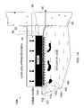
- FIG. 14 is a cross-sectional view of a first embodiment of an automatic screen cleaning device in accordance with a second aspect of the present invention with the float in the lowest position;
- FIG. 15 is a plan view of the screen of the screen cleaning device of FIG. 14 ;
- FIG. 16 is an enlarged view of a portion of FIG. 14 showing the detail of the screen cleaning rods and their interaction with the screen;
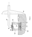
- FIG. 17 is a cross-sectional view of the “Y” notch orifice plate
- FIG. 18 is a cross-sectional view of the embodiment of FIG. 14 in a semi-open position with the float partially raised;
- FIG. 19 is a cross-sectional view of the embodiment of FIG. 14 in a fully open position with the float in its highest position;
- FIG. 20 is a cross-sectional view of the embodiment of FIG. 14 with the screen blocked and the float/rake descending to clean the screen.
- FIGS. 1 to 20 An embodiment of the present invention will now be described with reference to all of FIGS. 1 to 20 , in which common features are indicated using common figure references.
- FIG. 1 shows a pumping station 10 comprising a housing 20 containing a pump 25 , the housing 20 having a sewage inlet 30 , through which sewage is received from sewage inlet pipe 35 , and a sewage outlet 40 through which sewage is pumped for onward travel.
- the housing is also provided with an outfall outlet 50 through which sewage may leave the housing 20 when the sewage level within the housing 20 exceeds overflow level 55 .
- Sewage leaving housing 20 through outfall outlet 50 passes through outfall pipe 60 and finally exits outfall pipe 60 at a nearby river or stream 70 .
- a screen cleaning apparatus 100 is located within with housing 20 (shown in more detail in FIGS. 2 to 7 ) substantially adjacent the inlet 65 to outfall pipe 60 .
- Screen cleaning apparatus 100 comprises a screen member 110 and a rake member 120 .
- Rake member 120 comprises a body 122 with prongs 124 extending therefrom.
- a float member 130 is located adjacent rake member 120 and resilient members 126 in the form of springs are provided in engagement with float member 130 and the upper interior surface of screen cleaning apparatus 100 .
- Screen member 110 has a number of elongate spacers 112 defining gaps 114 therebetween, with each prong of rake member 120 extending through a respective elongate gap 112 of screen member 110 to clear any potentially adhered rag.
- sewage 140 containing rag 150 is received into housing 20 of pumping station 10 through inlet 30 of sewage inlet pipe 35 .
- Pump 25 then pumps the sewage 140 and rag 150 through sewage outlet 40 onward to its next destination.
- some rag may get drawn into the suction of the pump and passed forward under pressure to the next pumping station.
- the volume of sewage 140 received within housing 20 may vary depending on several influencing factors including, but not limited to, the flow of sewage 140 passing through sewage inlet pipe 35 and/or the efficiency/malfunctioning of pump 25 .
- sewage passes through screen cleaning apparatus 100 into outfall pipe 60 through outlet 50 .
- rag 150 floating within sewage 140 may adhere or become lodged against spacers 112 of screen member 110 . Sufficient adhesion/lodging of rag 150 in this manner may lead to full or partial blocking of gaps 114 in screen member 110 , thereby preventing passage of sufficient volumes of sewage 140 through screen member 110 to prevent overflow of sewage from housing 20 leading to flooding of sewage 140 at ground level. Thus, it is important the screen member 110 is kept clear of obstructions at all times.
- rake member 120 moves rises with the sewage surface level due to the application of force exerted on rake member 120 by float member 130 .
- any pieces of rag which have become lodged within the gaps 114 defined by spacers 112 of screen member 110 are dislodged by the movement of prongs 124 downwards between gaps 114 .
- the dislodged rag 150 is dislodged back into the volume of sewage contained within the housing 20 of pumping station 10 .
- the gaps 114 between spacers 112 of screen member 110 are automatically kept free of obstruction, thereby avoiding the blockage of screen member 110 and the overflow of sewage from pumping station 10 at ground level.
- the size of the gaps in the screen limits the dimensions of the rag passing through to overflow.
- FIGS. 8 and 9 show a further embodiment of an automatic screen cleaning apparatus in accordance with a first aspect of the present invention.
- Screen cleaning apparatus 100 A of FIGS. 8 and 9 closely resembles apparatus 100 of FIGS. 1 to 7 .
- screen member 110 A comprises a substantially planar member 114 A defining a plurality of apertures 112 A therethrough with 6 mm diameters.
- Rake member 120 A comprises a plurality of rods 124 A dimensioned so as to fit through respective apertures 112 A in screen member 110 A.
- Support rods 200 are provided to keep the rods 124 A of rake member 120 A aligned with respective apertures 112 A in screen member 110 A.
- rods 124 A clear respective apertures 112 A in screen member 110 A thereby allowing fluid to flow through apertures 112 A into screen cleaning apparatus 100 A and out through outfall pipe 60 .
- rods 124 A of rake member 120 A extend through respective apertures 112 A, thereby blocking the passage of fluid into apparatus 100 A.
- apertures 112 A Due to the dimensions of the apertures 112 A, there is a limitation on the size of rag that is able to pass through apertures 112 A into apparatus 100 A when rake member 120 A is in a raised position. Typically, the apertures 112 A will be dimensioned to prevent rag sized greater than 6 mm from passing through into apparatus 100 A. However, other dimensions may be applied to the apertures 120 A as required.
- Blockage of apertures 112 A in screen member 110 A is prevented as any lodged rag is dislodged by the movement of rods 124 A through respective apertures 112 A.
- apertures 112 A may be varied as desired in order to control the dimensions of rag which are prevented from passing through apertures 112 A into apparatus 100 A.
- Integral screen/float member 200 comprises a body 210 defining protrusions 220 extending from the body 210 .
- Body 210 of FIGS. 10 and 11 is equivalent to float member 130 of FIGS. 2 to 5
- protrusions 220 are equivalent to prongs 124 of rake member 120 of FIGS. 2 to 5 .
- FIGS. 12 and 13 A second embodiment of such a single unit screen member/float member arrangement is shown in FIGS. 12 and 13 in which integral screen/float member 200 comprises a body 210 defining protrusions 220 extending from the body 210 .
- Body 210 of FIGS. 12 and 13 is equivalent to float member 130 of FIGS. 8 and 9 and protrusions 220 of FIGS. 12 and 13 are equivalent to prongs 124 A of rake member 110 A of FIGS. 8 and 9 .
- An integral screen member/float member arrangement may comprise a one piece moulding, or the body (i.e. float member portion) may have protrusions cast into it.
- the body and protrusions may be manufactured separately and engaged with one another prior to installation within a screen cleaning apparatus in accordance with the present invention.
- FIGS. 14 to 20 A further embodiment of an automatic screen cleaning device in accordance with a second aspect of the present invention is shown in FIGS. 14 to 20 in which screen cleaning device 100 b is located within housing 20 .
- a “Y” notch orifice plate 80 located at the output of screen cleaning device 100 b such that it is substantially adjacent the inlet end of outfall outlet 50 .
- Screen cleaning device 100 b further comprises a screen member 110 b defining a plurality of spaced apertures 112 b , a float 130 b located above the screen member 110 b with rods 124 b extending from float 130 b towards screen 110 b and aligned with apertures 112 b.
- FIG. 15 shows a plan view of screen 110 b .
- Screen 110 b comprises a substantially planar member 114 b defining a plurality of apertures 112 b .
- Apertures 112 b preferably have a diameter of substantially 6 mm. It will be appreciated however that the cross-sectional shape and dimensions of apertures 112 b may be varied depending on the dimensions of rods 124 b and/or composition of rag 150 in order control the dimensions of rag that will be able to pass through screen 110 b.
- Effluent 140 flows through apertures 112 b , which are partially obstructed by shank 121 of the rod 124 b , across the top of screen 110 b , through the narrow portion 83 of “Y” notch orifice plate 80 , and through the outfall outlet 50 .
- FIG. 14 shows a cross-sectional view of the screen cleaning device 100 b in the closed position.
- the closed position is defined as the float 130 b resting on seat 101 and occurs when the level of effluent 140 is lower than the upper surface 102 of seat 101 .
- FIG. 14 shows the level of effluent 140 being above the level of the screen 110 b and below the level of upper surface 102 of seat 101 .
- FIG. 17 shows an end view of “Y” notch orifice plate 80 .
- the total area of the apertures 112 b is significantly greater than the area of outlet 50 in order to permit sufficient fluid flow through apparatus 100 b even when there is partial blockage of apertures 112 b .
- the total area of the “Y” notch orifice 81 may be around one quarter of the sum of the areas of apertures 112 b .
- other orifice shapes may be used such as but not limited to a “V” or “Y” shape.
- a feature of the orifice is that it comprises a portion 82 which defines a region of increasing aperture in a direction extending away from narrowed portion 83 as shown in FIGS. 17 .
- the dimensions of orifice 81 relative to the dimensions of the apertures 112 b may be varied.
- the total area of “Y” notch orifice 81 is substantially the same as the area of outlet 50 .
- the area of “Y” notch orifice 81 were substantially smaller than that of outlet 50 , the fluid flow out of apparatus 100 b would be restricted. There would be no added value to making the area of the “Y” notch orifice substantially greater than that of outlet 50 as the area of outlet 50 determines the rate of fluid flow through apparatus 100 b.
- the purpose of the Y notch orifice 81 or any other shaped orifice is to regulate the flow going out through outfall pipe 60 so that when the flow into the housing 100 b exceeds that of the flow out through outfall pipe 60 , the float is induced to rise, thereby allowing more flow into housing 100 b through screen 110 b .
- the greater the flow into the housing 100 b the further the float is lifted until the maximum flow through “Y” notch orifice 81 is achieved (within the constraints of the dimensions of the outflow pipe 60 ).
- the “Y” notch orifice 81 allows the housing 100 b to empty of liquid through outfall pipe 60 , thus resulting in the lowering of the float 130 b until rods 124 b extend through apertures 112 b in screen 110 b , thereby cleaning any obstructing rag from the screen 110 b .
- This cycle will then repeat itself as liquid flows into housing 100 b again lifting the float 130 b . This results in the screen being kept clean of rag.
- rods 124 b comprise two different lengths, only fifty percent of apertures 112 b will be obstructed by rod heads 122 at the same time.
- the apertures 112 b and “Y” orifice 81 are dimensioned such that when the float is at a height such that fifty percent of the apertures 112 b are substantially blocked by rod heads 122 and fifty percent of apertures 112 b are partially blocked by rod stems 121 the flow of effluent 140 through screen 110 b required to raise float 130 b is permitted. It will be appreciated that a greater variety of lengths of rods 124 b could be used to further reduce the restriction of flow of effluent 140 through apertures 112 b due to obstruction of apertures 112 b by rod heads 122 .
- Rods 124 b may be discreet components coupled to float 130 b .
- the plurality of rods 124 b may be mounted on a body to form a rake member which is, in turn, mounted on the float 130 b .
- rods 124 b may be formed integrally with float 130 b.
- FIG. 18 the level of effluent 140 has risen to lift float 130 b away from seat 101 .
- the shorter rods 124 b have been completely removed from their respective apertures 112 b which are now substantially free from obstruction.
- the flow rate of effluent 140 through screen 110 b is therefore increased. If a nett inflow of effluent 140 to screen cleaning device 100 b continues the level of effluent 140 and float 130 b will continue to rise until the fully open position shown in FIG. 9 is achieved, i.e. the float 130 b has reached its highest position within housing 20 .
- FIG. 19 shows the screen cleaning device in the fully open position. In this position apertures 112 b and “Y” orifice 81 are substantially free of obstruction. The dimensions of “Y” orifice 81 are such that the flow rate through “Y” notch orifice 81 is sufficient to meet the overflow requirements of pumping station 10 .
- FIG. 20 shows the screen cleaning device 100 b in the fully open position with the screen 110 b blocked by rag 150 . This may be caused by the flow of effluent 140 through screen 110 b causing pieces of rag 150 to become lodged in apertures 112 b.
- apertures 112 b become partially or completely blocked the flow of effluent 140 through screen 110 b will be restricted. If, as a result of complete or partial blockage of apertures 112 b , the flow of effluent 140 into the screen cleaning device 100 b becomes less than the flow of effluent 140 out of the screen cleaning device 100 b , via “Y” orifice 81 , the level of effluent 140 in the screen cleaning device 100 b will fall, as will float 130 b . As the float 130 b moves closer to the screen 110 b the aligned rods 124 b to pass through the apertures 112 b in screen 110 b dislodging any obstruction therein.
- the weight of the float is sufficient to dislodge any obstruction.
- rods 124 b extend below screen 110 b rag 150 trapped against the underside of screen 110 b is pushed away form the surface of screen 110 b .
- the dislodged rag will be swept away from the screen by the turbulence of the effluent and return to float in the wet well.
- the pumps may draw the rag in under suction and pass it forward. Otherwise, the rag will be removed by tanker during the scheduled well clean.
- Screen 110 b , rods 124 b and “Y” notch orifice plate 80 comprise materials such as but not limited to stainless steel, which will suffer substantially no deterioration when placed in contact with effluent for prolonged periods of time.
- an automatic screen cleaning member in accordance with the present invention also has application in other environments, for example, in brewing or any other filtration systems in which it is desired to keep screens free from blockages.
Landscapes
- Chemical & Material Sciences (AREA)
- Chemical Kinetics & Catalysis (AREA)
- Hydrology & Water Resources (AREA)
- Health & Medical Sciences (AREA)
- Public Health (AREA)
- Water Supply & Treatment (AREA)
- Engineering & Computer Science (AREA)
- Life Sciences & Earth Sciences (AREA)
- Business, Economics & Management (AREA)
- Emergency Management (AREA)
- Sewage (AREA)
- Electrical Discharge Machining, Electrochemical Machining, And Combined Machining (AREA)
- Surgical Instruments (AREA)
- Cleaning Or Drying Semiconductors (AREA)
Applications Claiming Priority (5)
| Application Number | Priority Date | Filing Date | Title |
|---|---|---|---|
| GB0703823.5 | 2007-02-27 | ||
| GB0703823A GB0703823D0 (en) | 2007-02-27 | 2007-02-27 | Cleaning device |
| GB0704557.8 | 2007-03-08 | ||
| GB0704557A GB0704557D0 (en) | 2007-03-08 | 2007-03-08 | Cleaning device |
| PCT/GB2008/000664 WO2008104773A1 (en) | 2007-02-27 | 2008-02-27 | Screen cleaning device and rake member for such a device |
Publications (2)
| Publication Number | Publication Date |
|---|---|
| US20100084348A1 US20100084348A1 (en) | 2010-04-08 |
| US8038889B2 true US8038889B2 (en) | 2011-10-18 |
Family
ID=39284695
Family Applications (1)
| Application Number | Title | Priority Date | Filing Date |
|---|---|---|---|
| US12/528,892 Expired - Fee Related US8038889B2 (en) | 2007-02-27 | 2008-02-27 | Cleaning device |
Country Status (5)
| Country | Link |
|---|---|
| US (1) | US8038889B2 (de) |
| EP (1) | EP2118387B1 (de) |
| AT (1) | ATE528449T1 (de) |
| GB (1) | GB2451914B (de) |
| WO (1) | WO2008104773A1 (de) |
Cited By (3)
| Publication number | Priority date | Publication date | Assignee | Title |
|---|---|---|---|---|
| US20130180902A1 (en) * | 2012-01-12 | 2013-07-18 | Phillip Clark Frey | Self-cleaning Septic Tank Filter |
| US10315136B2 (en) * | 2009-04-23 | 2019-06-11 | Noadiah S. Eckman | Self-clearing filter |
| US20220213677A1 (en) * | 2021-01-04 | 2022-07-07 | United States Government As Represented By The Secretary Of The Navy | In-Pipe Storm Water Filter |
Families Citing this family (5)
| Publication number | Priority date | Publication date | Assignee | Title |
|---|---|---|---|---|
| US9433971B2 (en) | 2012-10-04 | 2016-09-06 | The Goodyear Tire & Rubber Company | Atmospheric plasma treatment of reinforcement cords and use in rubber articles |
| US9441325B2 (en) | 2012-10-04 | 2016-09-13 | The Goodyear Tire & Rubber Company | Atmospheric plasma treatment of reinforcement cords and use in rubber articles |
| RU2018126325A (ru) * | 2015-12-18 | 2020-01-20 | Аксептенс Груп Пти Лтд | Грохот |
| CN109958603B (zh) * | 2019-02-19 | 2020-12-11 | 安徽富通环保节能科技股份有限公司 | 一种污水井用真空泵支座及其安装方法 |
| CN110106958A (zh) * | 2019-05-14 | 2019-08-09 | 上海斐晟企业管理有限公司 | 一种用于巨型坑体内建筑群的泄洪方法及其设备 |
Citations (16)
| Publication number | Priority date | Publication date | Assignee | Title |
|---|---|---|---|---|
| US1331935A (en) * | 1918-06-27 | 1920-02-24 | Shelley E Lee | Self-cleaning screen |
| US1551967A (en) * | 1925-09-01 | Fish-screening device | ||
| US1651321A (en) | 1927-08-06 | 1927-11-29 | Burkelman Charles | Drain protector |
| US3477579A (en) * | 1966-10-20 | 1969-11-11 | Fluid Dynamics Ltd | Self-clearing screening apparatus for use in irrigation and like projects |
| US3567032A (en) * | 1968-06-14 | 1971-03-02 | Monogram Ind Inc | Filter and pump for a recirculating sanitary system |
| US4214988A (en) * | 1978-04-27 | 1980-07-29 | Naffziger John D | Ditch water cleaning apparatus |
| US4642195A (en) * | 1981-07-01 | 1987-02-10 | Walter Nill | Screening system including a screen cleaning means for and a method of cleaning a screen in a waste water purification plant |
| US5079905A (en) * | 1990-05-29 | 1992-01-14 | Bergstrom Thomas A | Floating weed rake |
| US5164079A (en) * | 1989-07-18 | 1992-11-17 | Lenzing Aktiengesellschaft | Filtering apparatus for separating solid and suspended matter from a liquid |
| EP0672800A2 (de) | 1994-03-17 | 1995-09-20 | ENVIREX Inc. | Stangensieb mit zusammengesetzter, feinmaschiger Stangensiebanordnung |
| CH689426A5 (de) | 1992-07-24 | 1999-04-15 | Werner Nill | Siebrechenanordnung für Regenüberlaufbecken. |
| US5902477A (en) * | 1997-04-30 | 1999-05-11 | John Vena | Combined sewer overflow and storm water diverter screen |
| US5937473A (en) * | 1997-02-24 | 1999-08-17 | Lisowski; Walter E. | Intake clearing tool for jet-powered aquatic vehicles |
| US6132626A (en) * | 1995-08-19 | 2000-10-17 | Maguire Boss | Liquid filter |
| GB2367015A (en) | 2000-08-05 | 2002-03-27 | G & K Valve Services Ltd | A waste water filtration tank with an automatic flushing mechanism |
| GB2397538A (en) | 2003-01-23 | 2004-07-28 | G & K Valve Services Ltd | Filtration apparatus with automatic backflush |
-
2008
- 2008-02-27 AT AT08709540T patent/ATE528449T1/de not_active IP Right Cessation
- 2008-02-27 US US12/528,892 patent/US8038889B2/en not_active Expired - Fee Related
- 2008-02-27 WO PCT/GB2008/000664 patent/WO2008104773A1/en not_active Ceased
- 2008-02-27 EP EP20080709540 patent/EP2118387B1/de not_active Not-in-force
- 2008-02-27 GB GB0803631A patent/GB2451914B/en not_active Expired - Fee Related
Patent Citations (16)
| Publication number | Priority date | Publication date | Assignee | Title |
|---|---|---|---|---|
| US1551967A (en) * | 1925-09-01 | Fish-screening device | ||
| US1331935A (en) * | 1918-06-27 | 1920-02-24 | Shelley E Lee | Self-cleaning screen |
| US1651321A (en) | 1927-08-06 | 1927-11-29 | Burkelman Charles | Drain protector |
| US3477579A (en) * | 1966-10-20 | 1969-11-11 | Fluid Dynamics Ltd | Self-clearing screening apparatus for use in irrigation and like projects |
| US3567032A (en) * | 1968-06-14 | 1971-03-02 | Monogram Ind Inc | Filter and pump for a recirculating sanitary system |
| US4214988A (en) * | 1978-04-27 | 1980-07-29 | Naffziger John D | Ditch water cleaning apparatus |
| US4642195A (en) * | 1981-07-01 | 1987-02-10 | Walter Nill | Screening system including a screen cleaning means for and a method of cleaning a screen in a waste water purification plant |
| US5164079A (en) * | 1989-07-18 | 1992-11-17 | Lenzing Aktiengesellschaft | Filtering apparatus for separating solid and suspended matter from a liquid |
| US5079905A (en) * | 1990-05-29 | 1992-01-14 | Bergstrom Thomas A | Floating weed rake |
| CH689426A5 (de) | 1992-07-24 | 1999-04-15 | Werner Nill | Siebrechenanordnung für Regenüberlaufbecken. |
| EP0672800A2 (de) | 1994-03-17 | 1995-09-20 | ENVIREX Inc. | Stangensieb mit zusammengesetzter, feinmaschiger Stangensiebanordnung |
| US6132626A (en) * | 1995-08-19 | 2000-10-17 | Maguire Boss | Liquid filter |
| US5937473A (en) * | 1997-02-24 | 1999-08-17 | Lisowski; Walter E. | Intake clearing tool for jet-powered aquatic vehicles |
| US5902477A (en) * | 1997-04-30 | 1999-05-11 | John Vena | Combined sewer overflow and storm water diverter screen |
| GB2367015A (en) | 2000-08-05 | 2002-03-27 | G & K Valve Services Ltd | A waste water filtration tank with an automatic flushing mechanism |
| GB2397538A (en) | 2003-01-23 | 2004-07-28 | G & K Valve Services Ltd | Filtration apparatus with automatic backflush |
Cited By (5)
| Publication number | Priority date | Publication date | Assignee | Title |
|---|---|---|---|---|
| US10315136B2 (en) * | 2009-04-23 | 2019-06-11 | Noadiah S. Eckman | Self-clearing filter |
| US20130180902A1 (en) * | 2012-01-12 | 2013-07-18 | Phillip Clark Frey | Self-cleaning Septic Tank Filter |
| US9101858B2 (en) * | 2012-01-12 | 2015-08-11 | Phillip Clark Frey | Self-cleaning septic tank filter |
| US20220213677A1 (en) * | 2021-01-04 | 2022-07-07 | United States Government As Represented By The Secretary Of The Navy | In-Pipe Storm Water Filter |
| US11459744B2 (en) * | 2021-01-04 | 2022-10-04 | United States Of America As Represented By The Secretary Of The Navy | In-pipe storm water filter |
Also Published As
| Publication number | Publication date |
|---|---|
| GB2451914A (en) | 2009-02-18 |
| US20100084348A1 (en) | 2010-04-08 |
| EP2118387B1 (de) | 2011-10-12 |
| GB0803631D0 (en) | 2008-04-02 |
| ATE528449T1 (de) | 2011-10-15 |
| GB2451914B (en) | 2011-07-27 |
| WO2008104773A1 (en) | 2008-09-04 |
| EP2118387A1 (de) | 2009-11-18 |
Similar Documents
| Publication | Publication Date | Title |
|---|---|---|
| US8038889B2 (en) | Cleaning device | |
| US6478954B1 (en) | Debris collecting apparatus | |
| US20160075578A1 (en) | Biofiltration With Enhanced Sludge Handling | |
| CN115538567B (zh) | 一种海绵城市雨水排水调节系统 | |
| CN119015760A (zh) | 一种环保工程用工业污水净化装置 | |
| KR102030363B1 (ko) | 빗물 수집 시스템 | |
| US3948773A (en) | Automatic control for filtering equipment under pressure | |
| CN119080284A (zh) | 一种污水处理用多功能曝气装置 | |
| KR101047570B1 (ko) | 맨홀 | |
| JP4730603B2 (ja) | リチャージ工法およびそれに用いる地下水リチャージシステム | |
| KR101403502B1 (ko) | 스크린 일체형 펌프 게이트 장치 | |
| KR20020014640A (ko) | 어류 양식수조의 급배수장치 | |
| JP4603211B2 (ja) | 昇降式越流堰 | |
| GB2312177A (en) | Device for removing the surface layer of liquids | |
| US8104499B2 (en) | Precision siphon operated septic field dosing system with filtration and backwash | |
| CN115874703B (zh) | 一种自沉淀过滤毛细地漏 | |
| CN219825499U (zh) | 排水装置 | |
| KR20190122030A (ko) | 이물질 유입이 차단되는 맨홀 | |
| CN222677422U (zh) | 一种污水处理管反冲装置 | |
| CN119280918B (zh) | 一种建筑施工用雨水杂质分离装置 | |
| CN116180683B (zh) | 一种闸门运行装置 | |
| GB2549959A (en) | Automatic screen cleaning apparatus | |
| CN210288472U (zh) | 一种挡土墙结构 | |
| CN220142837U (zh) | 一种新型沉沙池 | |
| CN116623771A (zh) | 一种雨水过滤排放系统 |
Legal Events
| Date | Code | Title | Description |
|---|---|---|---|
| AS | Assignment |
Owner name: SAMATRIX LIMITED,UNITED KINGDOM Free format text: ASSIGNMENT OF ASSIGNORS INTEREST;ASSIGNOR:MUNN, SAMUEL, MR;REEL/FRAME:023218/0320 Effective date: 20090826 Owner name: SAMATRIX LIMITED, UNITED KINGDOM Free format text: ASSIGNMENT OF ASSIGNORS INTEREST;ASSIGNOR:MUNN, SAMUEL, MR;REEL/FRAME:023218/0320 Effective date: 20090826 |
|
| CC | Certificate of correction | ||
| REMI | Maintenance fee reminder mailed | ||
| LAPS | Lapse for failure to pay maintenance fees | ||
| STCH | Information on status: patent discontinuation |
Free format text: PATENT EXPIRED DUE TO NONPAYMENT OF MAINTENANCE FEES UNDER 37 CFR 1.362 |
|
| STCH | Information on status: patent discontinuation |
Free format text: PATENT EXPIRED DUE TO NONPAYMENT OF MAINTENANCE FEES UNDER 37 CFR 1.362 |
|
| FP | Lapsed due to failure to pay maintenance fee |
Effective date: 20151018 |