US8028678B2 - Direct injection alcohol engine with boost and spark control - Google Patents
Direct injection alcohol engine with boost and spark control Download PDFInfo
- Publication number
- US8028678B2 US8028678B2 US13/053,672 US201113053672A US8028678B2 US 8028678 B2 US8028678 B2 US 8028678B2 US 201113053672 A US201113053672 A US 201113053672A US 8028678 B2 US8028678 B2 US 8028678B2
- Authority
- US
- United States
- Prior art keywords
- fuel
- engine
- alcohol content
- cylinder
- alcohol
- Prior art date
- Legal status (The legal status is an assumption and is not a legal conclusion. Google has not performed a legal analysis and makes no representation as to the accuracy of the status listed.)
- Expired - Fee Related
Links
Images


Classifications
-
- F—MECHANICAL ENGINEERING; LIGHTING; HEATING; WEAPONS; BLASTING
- F02—COMBUSTION ENGINES; HOT-GAS OR COMBUSTION-PRODUCT ENGINE PLANTS
- F02D—CONTROLLING COMBUSTION ENGINES
- F02D41/00—Electrical control of supply of combustible mixture or its constituents
- F02D41/0025—Controlling engines characterised by use of non-liquid fuels, pluralities of fuels, or non-fuel substances added to the combustible mixtures
-
- F—MECHANICAL ENGINEERING; LIGHTING; HEATING; WEAPONS; BLASTING
- F02—COMBUSTION ENGINES; HOT-GAS OR COMBUSTION-PRODUCT ENGINE PLANTS
- F02B—INTERNAL-COMBUSTION PISTON ENGINES; COMBUSTION ENGINES IN GENERAL
- F02B47/00—Methods of operating engines involving adding non-fuel substances or anti-knock agents to combustion air, fuel, or fuel-air mixtures of engines
- F02B47/04—Methods of operating engines involving adding non-fuel substances or anti-knock agents to combustion air, fuel, or fuel-air mixtures of engines the substances being other than water or steam only
-
- F—MECHANICAL ENGINEERING; LIGHTING; HEATING; WEAPONS; BLASTING
- F02—COMBUSTION ENGINES; HOT-GAS OR COMBUSTION-PRODUCT ENGINE PLANTS
- F02D—CONTROLLING COMBUSTION ENGINES
- F02D19/00—Controlling engines characterised by their use of non-liquid fuels, pluralities of fuels, or non-fuel substances added to the combustible mixtures
- F02D19/06—Controlling engines characterised by their use of non-liquid fuels, pluralities of fuels, or non-fuel substances added to the combustible mixtures peculiar to engines working with pluralities of fuels, e.g. alternatively with light and heavy fuel oil, other than engines indifferent to the fuel consumed
- F02D19/0602—Control of components of the fuel supply system
- F02D19/0607—Control of components of the fuel supply system to adjust the fuel mass or volume flow
- F02D19/061—Control of components of the fuel supply system to adjust the fuel mass or volume flow by controlling fuel injectors
-
- F—MECHANICAL ENGINEERING; LIGHTING; HEATING; WEAPONS; BLASTING
- F02—COMBUSTION ENGINES; HOT-GAS OR COMBUSTION-PRODUCT ENGINE PLANTS
- F02D—CONTROLLING COMBUSTION ENGINES
- F02D19/00—Controlling engines characterised by their use of non-liquid fuels, pluralities of fuels, or non-fuel substances added to the combustible mixtures
- F02D19/06—Controlling engines characterised by their use of non-liquid fuels, pluralities of fuels, or non-fuel substances added to the combustible mixtures peculiar to engines working with pluralities of fuels, e.g. alternatively with light and heavy fuel oil, other than engines indifferent to the fuel consumed
- F02D19/0663—Details on the fuel supply system, e.g. tanks, valves, pipes, pumps, rails, injectors or mixers
- F02D19/0686—Injectors
- F02D19/0689—Injectors for in-cylinder direct injection
-
- F—MECHANICAL ENGINEERING; LIGHTING; HEATING; WEAPONS; BLASTING
- F02—COMBUSTION ENGINES; HOT-GAS OR COMBUSTION-PRODUCT ENGINE PLANTS
- F02D—CONTROLLING COMBUSTION ENGINES
- F02D19/00—Controlling engines characterised by their use of non-liquid fuels, pluralities of fuels, or non-fuel substances added to the combustible mixtures
- F02D19/06—Controlling engines characterised by their use of non-liquid fuels, pluralities of fuels, or non-fuel substances added to the combustible mixtures peculiar to engines working with pluralities of fuels, e.g. alternatively with light and heavy fuel oil, other than engines indifferent to the fuel consumed
- F02D19/08—Controlling engines characterised by their use of non-liquid fuels, pluralities of fuels, or non-fuel substances added to the combustible mixtures peculiar to engines working with pluralities of fuels, e.g. alternatively with light and heavy fuel oil, other than engines indifferent to the fuel consumed simultaneously using pluralities of fuels
- F02D19/082—Premixed fuels, i.e. emulsions or blends
- F02D19/084—Blends of gasoline and alcohols, e.g. E85
-
- F—MECHANICAL ENGINEERING; LIGHTING; HEATING; WEAPONS; BLASTING
- F02—COMBUSTION ENGINES; HOT-GAS OR COMBUSTION-PRODUCT ENGINE PLANTS
- F02D—CONTROLLING COMBUSTION ENGINES
- F02D19/00—Controlling engines characterised by their use of non-liquid fuels, pluralities of fuels, or non-fuel substances added to the combustible mixtures
- F02D19/06—Controlling engines characterised by their use of non-liquid fuels, pluralities of fuels, or non-fuel substances added to the combustible mixtures peculiar to engines working with pluralities of fuels, e.g. alternatively with light and heavy fuel oil, other than engines indifferent to the fuel consumed
- F02D19/08—Controlling engines characterised by their use of non-liquid fuels, pluralities of fuels, or non-fuel substances added to the combustible mixtures peculiar to engines working with pluralities of fuels, e.g. alternatively with light and heavy fuel oil, other than engines indifferent to the fuel consumed simultaneously using pluralities of fuels
- F02D19/082—Premixed fuels, i.e. emulsions or blends
- F02D19/085—Control based on the fuel type or composition
- F02D19/087—Control based on the fuel type or composition with determination of densities, viscosities, composition, concentration or mixture ratios of fuels
-
- F—MECHANICAL ENGINEERING; LIGHTING; HEATING; WEAPONS; BLASTING
- F02—COMBUSTION ENGINES; HOT-GAS OR COMBUSTION-PRODUCT ENGINE PLANTS
- F02D—CONTROLLING COMBUSTION ENGINES
- F02D23/00—Controlling engines characterised by their being supercharged
- F02D23/02—Controlling engines characterised by their being supercharged the engines being of fuel-injection type
-
- F—MECHANICAL ENGINEERING; LIGHTING; HEATING; WEAPONS; BLASTING
- F02—COMBUSTION ENGINES; HOT-GAS OR COMBUSTION-PRODUCT ENGINE PLANTS
- F02D—CONTROLLING COMBUSTION ENGINES
- F02D37/00—Non-electrical conjoint control of two or more functions of engines, not otherwise provided for
- F02D37/02—Non-electrical conjoint control of two or more functions of engines, not otherwise provided for one of the functions being ignition
-
- F—MECHANICAL ENGINEERING; LIGHTING; HEATING; WEAPONS; BLASTING
- F02—COMBUSTION ENGINES; HOT-GAS OR COMBUSTION-PRODUCT ENGINE PLANTS
- F02D—CONTROLLING COMBUSTION ENGINES
- F02D41/00—Electrical control of supply of combustible mixture or its constituents
- F02D41/0002—Controlling intake air
- F02D41/0007—Controlling intake air for control of turbo-charged or super-charged engines
-
- F—MECHANICAL ENGINEERING; LIGHTING; HEATING; WEAPONS; BLASTING
- F02—COMBUSTION ENGINES; HOT-GAS OR COMBUSTION-PRODUCT ENGINE PLANTS
- F02B—INTERNAL-COMBUSTION PISTON ENGINES; COMBUSTION ENGINES IN GENERAL
- F02B75/00—Other engines
- F02B75/12—Other methods of operation
- F02B2075/125—Direct injection in the combustion chamber for spark ignition engines, i.e. not in pre-combustion chamber
-
- F—MECHANICAL ENGINEERING; LIGHTING; HEATING; WEAPONS; BLASTING
- F02—COMBUSTION ENGINES; HOT-GAS OR COMBUSTION-PRODUCT ENGINE PLANTS
- F02D—CONTROLLING COMBUSTION ENGINES
- F02D41/00—Electrical control of supply of combustible mixture or its constituents
- F02D41/0002—Controlling intake air
- F02D2041/001—Controlling intake air for engines with variable valve actuation
-
- F—MECHANICAL ENGINEERING; LIGHTING; HEATING; WEAPONS; BLASTING
- F02—COMBUSTION ENGINES; HOT-GAS OR COMBUSTION-PRODUCT ENGINE PLANTS
- F02D—CONTROLLING COMBUSTION ENGINES
- F02D41/00—Electrical control of supply of combustible mixture or its constituents
- F02D41/30—Controlling fuel injection
- F02D41/38—Controlling fuel injection of the high pressure type
- F02D2041/389—Controlling fuel injection of the high pressure type for injecting directly into the cylinder
-
- F—MECHANICAL ENGINEERING; LIGHTING; HEATING; WEAPONS; BLASTING
- F02—COMBUSTION ENGINES; HOT-GAS OR COMBUSTION-PRODUCT ENGINE PLANTS
- F02D—CONTROLLING COMBUSTION ENGINES
- F02D2200/00—Input parameters for engine control
- F02D2200/02—Input parameters for engine control the parameters being related to the engine
- F02D2200/06—Fuel or fuel supply system parameters
- F02D2200/0611—Fuel type, fuel composition or fuel quality
-
- F—MECHANICAL ENGINEERING; LIGHTING; HEATING; WEAPONS; BLASTING
- F02—COMBUSTION ENGINES; HOT-GAS OR COMBUSTION-PRODUCT ENGINE PLANTS
- F02D—CONTROLLING COMBUSTION ENGINES
- F02D2250/00—Engine control related to specific problems or objectives
- F02D2250/18—Control of the engine output torque
-
- Y—GENERAL TAGGING OF NEW TECHNOLOGICAL DEVELOPMENTS; GENERAL TAGGING OF CROSS-SECTIONAL TECHNOLOGIES SPANNING OVER SEVERAL SECTIONS OF THE IPC; TECHNICAL SUBJECTS COVERED BY FORMER USPC CROSS-REFERENCE ART COLLECTIONS [XRACs] AND DIGESTS
- Y02—TECHNOLOGIES OR APPLICATIONS FOR MITIGATION OR ADAPTATION AGAINST CLIMATE CHANGE
- Y02T—CLIMATE CHANGE MITIGATION TECHNOLOGIES RELATED TO TRANSPORTATION
- Y02T10/00—Road transport of goods or passengers
- Y02T10/10—Internal combustion engine [ICE] based vehicles
- Y02T10/12—Improving ICE efficiencies
-
- Y—GENERAL TAGGING OF NEW TECHNOLOGICAL DEVELOPMENTS; GENERAL TAGGING OF CROSS-SECTIONAL TECHNOLOGIES SPANNING OVER SEVERAL SECTIONS OF THE IPC; TECHNICAL SUBJECTS COVERED BY FORMER USPC CROSS-REFERENCE ART COLLECTIONS [XRACs] AND DIGESTS
- Y02—TECHNOLOGIES OR APPLICATIONS FOR MITIGATION OR ADAPTATION AGAINST CLIMATE CHANGE
- Y02T—CLIMATE CHANGE MITIGATION TECHNOLOGIES RELATED TO TRANSPORTATION
- Y02T10/00—Road transport of goods or passengers
- Y02T10/10—Internal combustion engine [ICE] based vehicles
- Y02T10/30—Use of alternative fuels, e.g. biofuels
Definitions
- alcohol has been recognized as an attractive alternative source of energy, and more particularly a fuel for automotive applications.
- Various engine systems may be used with alcohol fuels, utilizing various engine technologies such as turbo-chargers, super-chargers, etc.
- various approaches may be used to control alcohol-fuelled engines with such devices, including adjustment of boost or spark timing in dependence upon an alcohol content of the engine fuel, and various operating conditions.
- the inventors herein have recognized several interrelated issues with alcohol-fuelled engines involving the fuel delivery system, and found that it is possible to operate the engine system to achieve improved engine performance with an alcohol fuel or blend by varying the amounts, timing, and number of injections.
- an engine system for an engine having at least a cylinder and combusting a fuel, the system comprising: a direct injection fuel injector coupled to the cylinder; an intake charge boosting device coupled to the engine and fluidly coupled to the cylinder; and a control system for varying at least a spark timing of the cylinder and boost amount of said device as an alcohol content of the directly injected fuel varies, said system operating the engine to produce increased peak torque output when said alcohol content is increased, at least during one condition.
- peak engine torque at least for some conditions, can be increased when using a fuel with increased alcohol compared to another fuel with less alcohol content. Such performance can be achieved using the above approach, even though the fuel with increased alcohol may have a reduced energy density.
- the improved performance can provide various benefits, such as improved towing capacity, improved acceleration, and/or various others.
- use of such alternative fuels may also provide reduced emissions and various other environmental and/or economic advantages.
- use of direct injection fuel can reduce the effect of varying amounts of alcohol on intake system puddling.
- the improved air-fuel ratio control can then be used to further reduce the likelihood of knock by providing more appropriate spark timing.
- improved marketing and/or advertising may be achieved. For example, it may be possible to inform potential consumers that a vehicle having an engine (with one or more of the features described herein) may be able to obtain improved vehicle performance when using a fuel with increased alcohol, rather than simply maintaining performance or achieving degraded performance.
- FIG. 1 shows a generic engine system
- FIG. 2 shows a partial engine view
- FIG. 3 shows an engine with a turbocharger
- FIG. 4 shows example fuel tank and pump configurations
- FIG. 5A shows a routine for adjusting fuel injection parameters taking into account an amount of alcohol in the fuel system
- FIG. 5B shows various examples of variable injection timing and number of injections per cycle
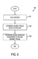
- FIG. 6 shows a flow chart illustrating the process sequence of the engine
- FIG. 7 shows a flow chart schematically showing how the operating parameters are determined
- FIG. 8 shows a process control flow chart illustrating how the transmission and cooling system are governed by torque, speed, and the pedal position
- FIGS. 9-10 show flow charts outlining an example advertising and marketing strategy to sell a vehicle with various engine features.
- FIG. 1 shows an engine 10 receiving delivery of a plurality of substances ( 1 , 2 , . . . , N) as indicated by arrow 8 .
- the various substances may include multiple different fuel blends or other alternatives.
- multiple different substances having different gasoline and/or alcohol and/or water concentrations may be delivered to the engine, and may be delivered in a mixed state, or separately delivered.
- the relative amounts and/or ratios of the different substances provided to the engine may be controlled by a controller 6 in response to operating conditions, which may be provided by and/or inferred via sensor(s) 4 .
- the relative amounts and/or ratios may be determined by the fuel blend added to the vehicle by the customer, and thus may not significantly vary during operation.
- the different substances may represent different fuels having different levels of alcohol, including one substance being gasoline and the other being ethanol.
- engine 10 may use gasoline as a first substance and an alcohol containing fuel such as ethanol, methanol, a mixture of gasoline and ethanol (e.g., E85 which is approximately 85% ethanol and 15% gasoline), a mixture of gasoline and methanol (e.g., M85 which is approximately 85% methanol and 15% gasoline), a mixture of an alcohol and water, a mixture of an alcohol, water, and gasoline, etc as a second substance.
- the first substance may be a gasoline alcohol blend with a lower alcohol concentration than a gasoline alcohol blend of a second substance.
- a fuel having alcohol e.g., ethanol
- This phenomenon combined with increased compression ratio, and/or boosting and/or engine downsizing, can then be used to obtain fuel economy benefits (by reducing the knock limitations on the engine), while also allowing engine operation with improved engine output torque, for example.
- engine 10 uses a direct injector 66 .
- engine 10 is capable of using a plurality of different fuel blends.
- engine 10 may use a mixture of gasoline and an alcohol containing fuel such as ethanol, methanol, a mixture of gasoline and ethanol (e.g., E85 which is approximately 85% ethanol and 15% gasoline), a mixture of gasoline and methanol (e.g., M85 which is approximately 85% methanol and 15% gas), etc.
- Direct injector 66 may be used to inject a mixture of gasoline and an alcohol based fuel, where the ratio of the two fuel quantities in the mixture may be adjusted by controller 12 via a mixing valve, for example. In another embodiment, different sized injectors and different fuels may be used.
- Internal combustion engine 10 comprising a plurality of combustion chambers, is controlled by electronic engine controller 12 .
- Combustion chamber 30 of engine 10 is shown including combustion chamber walls 32 with piston 36 positioned therein and connected to crankshaft 40 .
- a starter motor (not shown) may be coupled to crankshaft 40 via a flywheel (not shown), or alternatively direct engine starting may be used.
- piston 36 may include a recess or bowl (not shown) to help in forming stratified charges of air and fuel, if desired.
- a flat piston may be used.
- Combustion chamber, or cylinder, 30 is shown communicating with intake manifold 44 and exhaust manifold 48 via respective intake valves 52 a and 52 b (not shown), and exhaust valves 54 a and 54 b (not shown).
- intake valves 52 a and 52 b not shown
- exhaust valves 54 a and 54 b not shown
- four valves per cylinder may be used, in another example, a single intake and single exhaust valve per cylinder may also be used. In still another example, two intake valves and one exhaust valve per cylinder may be used.
- Combustion chamber 30 has an associated compression ratio, which is the ratio of volumes when piston 36 is at bottom center and top center.
- the compression ratio is in the range of 9:1 to 10:1
- the compression ratio can be raised due to the mitigating effects that octane, latent enthalpy of vaporization, and direct injection have on knock.
- Fuel injector 66 is shown directly coupled to combustion chamber 30 for delivering injected fuel directly therein in proportion to the pulse width of signal dfpw received from controller 12 via electronic driver 68 . While FIG. 2 shows injector 66 as a side injector, it may also be located overhead of the piston, such as near the position of spark plug 92 . Such a position may improve mixing and combustion due to the lower volatility of some alcohol based fuels. Alternatively, the injector may be located overhead and near the intake valve to improve mixing. Additional fuel injectors may also be used.
- Fuel and/or water may be delivered to fuel injector 66 by a high pressure fuel system (not shown) including a fuel tank, fuel pumps, and a fuel rail.
- fuel and/or water may be delivered by a single stage fuel pump at lower pressure, in which case the timing of the direct fuel injection may be more limited during the compression stroke than if a high pressure fuel system is used.
- the fuel line may have a pressure transducer providing a signal to controller 12 .
- Intake manifold 44 is shown communicating with throttle body 58 via throttle plate 62 .
- throttle plate 62 is coupled to electric motor 94 so that the position of elliptical throttle plate 62 is controlled by controller 12 via electric motor 94 .
- This configuration may be referred to as electronic throttle control (ETC), which can also be utilized during idle speed control.
- ETC electronic throttle control
- a bypass air passageway is arranged in parallel with throttle plate 62 to control inducted airflow during idle speed control via an idle control by-pass valve positioned within the air passageway.
- throttle plate 62 is actuated by the operator of the vehicle, the cable, or other device, between the accelerator pedal and the throttle valve not shown.
- Exhaust gas sensor 76 is shown coupled to exhaust manifold 48 upstream of catalytic converter 70 (where sensor 76 can correspond to various different sensors).
- sensor 76 may be any of many known sensors for providing an indication of exhaust gas air/fuel ratio such as a linear oxygen sensor, a UEGO, a two-state oxygen sensor, an EGO, a HEGO, or an HC or CO sensor.
- sensor 76 is a two-state oxygen sensor that provides signal EGO to controller 12 which converts signal EGO into two-state signal EGOS.
- a high voltage state of signal EGOS indicates exhaust gases are rich of stoichiometry and a low voltage state of signal EGOS indicates exhaust gases are lean of stoichiometry.
- Signal EGOS may be used to advantage during feedback air/fuel control to maintain average air/fuel at stoichiometry during a stoichiometric, homogeneous mode of operation.
- Distributorless ignition system 88 provides ignition spark to combustion chamber 30 via spark plug 92 in response to spark advance signal SA from controller 12 .
- Controller 12 may cause combustion chamber 30 to operate in a variety of combustion modes, including a homogeneous air/fuel mode and/or a stratified air/fuel mode by controlling injection timing, injection amounts, spray patterns, etc.
- stratified layers may be formed by operating injector 66 during a compression stroke.
- a homogenous mixture may be formed by operating injector 66 during an intake stroke (which may be open valve injection).
- multiple injections from injector 66 may be used during one or more strokes (e.g., intake and/or compression).
- a combination of a stratified and homogenous mixtures may be formed in the chamber. Even further examples may include the use of different injection timings and mixture formations under different conditions, as described below.
- Controller 12 can adjust the amount of fuel delivered by fuel injector 66 so that the homogeneous or stratified air/fuel mixtures or combinations thereof formed in chamber 30 can be selected to be at stoichiometry, a value rich of stoichiometry, or a value lean of stoichiometry.
- Emission control device 72 is shown positioned downstream of catalytic converter 70 .
- Emission control device 72 may be a three-way catalyst, particulate filter, NOx trap, or combinations thereof.
- Controller 12 is shown as a microcomputer, including microprocessor unit 102 , input/output ports 104 , an electronic storage medium for executable programs and calibration values shown as read only memory chip 106 in this particular example, random access memory 108 , keep alive memory 110 , and a conventional data bus.
- Controller 12 is shown receiving various signals from sensors coupled to engine 10 , in addition to those signals previously discussed, including measurement of inducted mass air flow (MAF) from mass air flow sensor 100 coupled to throttle body 58 ; engine coolant temperature (ECT) from temperature sensor 112 coupled to cooling sleeve 114 ; a profile ignition pickup signal (PIP) from Hall effect sensor 118 coupled to crankshaft 40 ; and throttle position TP from throttle position sensor 120 ; absolute manifold pressure signal MAP from sensor 122 ; an indication of knock from knock sensor 182 ; and an indication of absolute or relative ambient humidity from sensor 180 .
- MAF mass air flow
- ECT engine coolant temperature
- PIP profile ignition pickup signal
- Engine speed signal RPM is generated by controller 12 from signal PIP in a conventional manner and manifold pressure signal MAP from a manifold pressure sensor provides an indication of vacuum, or pressure, in the intake manifold. During stoichiometric operation, this sensor can give an indication of engine load. Further, this sensor, along with engine speed, can provide an estimate of charge (including air) inducted into the cylinder. In one example, sensor 118 , which is also used as an engine speed sensor, produces a predetermined number of equally spaced pulses every revolution of the crankshaft.
- camshaft 130 of engine 10 is shown communicating with rocker arms 132 and 134 for actuating intake valves 52 a , 52 b and exhaust valves 54 a , 54 b .
- Camshaft 130 is directly coupled to housing 136 .
- Housing 136 forms a toothed wheel having a plurality of teeth 138 .
- Housing 136 is mechanically coupled to crankshaft 40 via a timing chain or belt (not shown). Therefore, housing 136 and camshaft 130 can rotate at a speed substantially equivalent to 1 ⁇ 2 of the speed of the crankshaft, or other suitable speed.
- the relative position of camshaft 130 to crankshaft 40 can be varied by hydraulic pressures in advance chamber 142 and retard chamber 144 .
- advance chamber 142 By allowing high pressure hydraulic fluid to enter advance chamber 142 , the relative relationship between camshaft 130 and crankshaft 40 is advanced.
- intake valves 52 a , 52 b and exhaust valves 54 a , 54 b open and close at a time earlier than normal relative to crankshaft 40 .
- the relative relationship between camshaft 130 and crankshaft 40 is retarded.
- intake valves 52 a , 52 b , and exhaust valves 54 a , 54 b open and close at a time later than normal relative to crankshaft 40 .
- variable intake cam timing variable exhaust cam timing
- variable valve lift may also be used.
- camshaft profile switching may be used to provide a plurality (usually two) cam profiles which can be selected based on operating conditions.
- the valvetrain may be roller finger follower, direct acting mechanical bucket, electromechanical, electrohydraulic, or other alternatives to rocker arms.
- teeth 138 being coupled to housing 136 and camshaft 130 , allow for measurement of relative cam position via cam timing sensor 150 providing signal VCT to controller 12 .
- Teeth 1 , 2 , 3 , and 4 are preferably used for measurement of cam timing and are equally spaced (for example, in a V-8 dual bank engine, spaced 90 degrees apart from one another) while tooth 5 is preferably used for cylinder identification, as described later herein.
- controller 12 sends control signals (LACT, RACT) to conventional solenoid valves (not shown) to control the flow of hydraulic fluid either into advance chamber 142 , retard chamber 144 , or neither.
- Relative cam timing can be measured in a variety of ways.
- the time, or rotation angle, between the rising edge of the PIP signal and receiving a signal from one of the plurality of teeth 138 on housing 136 gives a measure of the relative cam timing.
- a measure of cam timing for a particular bank is received four times per revolution, with the extra signal used for cylinder identification.
- Sensor 160 may also provide an indication of oxygen concentration in the exhaust gas via signal 162 , which provides controller 12 a voltage indicative of the O2 concentration.
- sensor 160 can be a HEGO, UEGO, EGO, or other type of exhaust gas sensor. Also note that, as described above with regard to sensor 76 , sensor 160 can correspond to various different sensors.
- FIG. 2 merely shows one cylinder of a multi-cylinder engine, and it is understood that each cylinder has its own set of intake/exhaust valves, fuel injectors, spark plugs, etc.
- engine 10 may be coupled to various boosting devices, such as a supercharger or turbocharger, as shown in FIG. 3 .
- desired torque may also be maintained by adjusting wastegate and/or compressor bypass valves.
- engine 10 may have a turbocharger 319 , which has a turbine 319 a coupled to the exhaust manifold 48 and a compressor 319 b coupled to the intake manifold 44 . While FIG. 3 does not show an intercooler, one may optionally be used.
- Turbine 319 a is typically coupled to compressor 319 b via a drive shaft 315 .
- Various types of turbochargers and arrangements may be used. For example, a variable geometry turbocharger (VGT) may be used where the geometry of the turbine and/or compressor may be varied during engine operation by controller 12 .
- VVT variable geometry turbocharger
- VNT variable nozzle turbocharger
- FIG. 3 shows an example bypass valve 320 around turbine 319 a and an example bypass valve 322 around compressor 319 b , where each valve may be controlled via controller 12 .
- the valves may be located within the turbine or compressor, or may be a variable nozzle.
- twin turbocharger arrangement and/or a sequential turbocharger arrangement, may be used if desired.
- multiple adjustable turbocharger and/or stages it may be desirable to vary a relative amount of expansion though the turbocharger, depending on operating conditions (e.g. manifold pressure, airflow, engine speed, etc.).
- a mechanically or electrically driven supercharger may be used, if desired.
- a fuel tank 400 is shown for holding a fuel, such as gasoline and an alcohol blend.
- the fuel tank has an internal fuel pump 402 , where the internal fuel pump is a lower pressure fuel pump.
- a fuel pump 404 is coupled to the lower pressure fuel pump 402 by fuel line 406 , where the fuel pump is a higher pressure fuel pump.
- Higher pressure external fuel pump 404 is coupled to a fuel rail 408 having fuel injectors 410 coupled thereto.
- the fuel pressure at the injector may be adjusted by adjusting parameters such as the pump operation of one of pumps 402 and/or 404 , for example.
- the routine reads an alcohol content of the fuel.
- the alcohol content of the fuel may be a percent alcohol, mass ratio of alcohol, volume ratio of alcohol, an amount of oxygen in the fuel, or various other indications of an amount of alcohol in the fuel.
- the indication may be provided via an alcohol sensor, or may be generated from an estimate based on operating conditions, or combinations thereof.
- An estimate of alcohol content of the fuel may be formed using feedback from an exhaust gas sensor, in addition to other parameters, such as, for example, a mass airflow amount, a fuel injection pulsewidth, a manifold pressure, and/or others.
- the routine reads other operating conditions that may be used to adjust fuel injection timings and/or amounts, such as, for example, engine coolant temperature, feedback from a knock sensor, cylinder air amount, manifold pressure, air charge temperature, manifold temperature, desired air-fuel ratio, spark timing, atmospheric pressure, and/or various other parameters.
- the routine determines whether to adjust, and if so does adjust, fuel injection pressure based on a desired engine output torque and engine speed given the alcohol content of the fuel. Because alcohols are partially oxygenated, (ethanol is CH 5 OH, for example), they liberate a lesser amount of energy (lower heating value) when oxidized during combustion than a non-oxygenated hydrocarbon, like gasoline. The mass of fuel injected is increased as a function of alcohol content to provide the same combustion energy as gasoline, which requires a greater dynamic range from the fuel system. The pulse width may be adjusted to provide the desired amount of fuel.
- the routine determines a number of injections per engine cycle to be performed based on conditions and the amount of alcohol in the fuel. For example, as the amount of alcohol in the fuel increases, a greater or lesser number of injections for a given operating condition (e.g., a given speed/load condition) may be selected. Also, in the case of multiple injections per power cycle, a greater fraction of fuel may injected in an earlier injection as alcohol content increases so that there is more time for vaporization.
- a given operating condition e.g., a given speed/load condition
- the routine determines an injection timing (or timings in the case of multiple injections per cycle) based on conditions and the alcohol amount of the fuel. For example, injection timing of one or more injections may be advanced with increased alcohol in the fuel to take advantage of higher latent enthalpy of vaporization of alcohol to allow more time for vaporization. In one example, the injection timing may be advanced as a function of alcohol content and also the nature of the alcohol (e.g., ethanol vs. methanol). More injection timing advance may be used for methanol than ethanol because of its relatively higher latent enthalpy of vaporization, for example. Also, the timing of the injections may be adjusted based on the number of injections.
- injection timing may be advanced toward the period where there is pushback into the intake as a function of alcohol content. In this way, vaporization of the alcohol fuel can be aided by passing by the intake valve (twice, out and in). By cooling the intake system in this way, the charge density rammed into the combustion chamber can be increased thereby improving peak torque output of the engine. As such, injection timing may be adjusted based on engine torque and alcohol content to improve engine output.
- the controller may increase boost on a variable geometry turbocharger (or via wastegate control) as a function of the increased octane in fuel due to the alcohol content. Due to direct injection into the cylinder, the cooling effect of the vaporization of the fuel occurs in the cylinder. This can increase the cooling compared to port injection and allows a greater boost without incurring knock.
- the controller may adjust valve timing to increase valve overlap and inject fuel having alcohol at least partially during the valve overlap period to enhance the charge cooling effect with increased alcohol in the fuel.
- intake valve timing may be advanced and/or exhaust valve timing may be retarded as will be described below with reference to FIG. 5B , for example.
- ignition timing and/or valve timing may also be adjusted in response to an alcohol amount of the fuel.
- variable injection timing and number of injections per cycle are illustrated in FIG. 5B , where the dashed vertical lines indicate intake valve opening and intake valve closing.
- the intake valve opening duration may be approximately 248° and the exhaust valve opening duration may be approximately 240°, wherein the intake valve is opened at approximately 10° before top dead center of the intake stroke and the intake valve is closed at approximately 58° after bottom dead center of the intake stroke, and the exhaust valve is opened at approximately 50° before bottom dead center of the expansion stroke and the exhaust valve is closed at approximately 10° after top dead center of the intake stroke.
- the above valve control scenario is just one example and that other suitable valve timings may be used.
- Various parameters may affect the adjustments shown between the graphs of FIG. 5B , as noted herein, including an alcohol amount of the fuel and/or other operating parameters such as alcohol type, fuel injection timing, number of fuel injection pulses, fuel injection supply pressure, boosting, knock detection, temperature, engine starting, or others.
- first graph (I) a single injection is shown occurring partially during the intake stroke and ending after the close of the intake valve.
- the injection occurs partially during an open intake valve.
- the injection is advanced compared to the injection timing in the second graph (II), which shows both a shorter duration of fuel injection, and a later timing during a compression stroke.
- the shorter duration may be to compensate for an increased energy density and lower alcohol content, for example.
- the third graph (III) shows multiple injections (two) during the cycle, both during the compression stroke. However, based on alcohol content and/or other parameters, injections may occur during the intake stroke as well as during the compression stroke as shown by the fourth graph (IV).
- the relative amount of the injections may be adjusted based on alcohol content of the fuel and/or other parameters.
- the fifth graph (V) illustrates how changes in alcohol content of the fuel can affect the duration between injections as well.
- the sixth graph (VI) illustrates an example of variable timing, relative amounts of injection, and timing between injections, being varied in response to parameters such as alcohol content of the fuel.
- the last graph (VII) illustrates injection timing using pushback effects with valve overlap. As noted above, such operation may be used to further take advantage of charge cooling/vaporization effects with increased alcohol content in the fuel to increase torque of the engine while reducing knock effects.
- routine 600 for determining desired engine operation parameters in response to the fuel composition and driver demand to control engine and/or powertrain torque.
- routine 600 adjusts the torque of an engine to compensate for variations in fuel composition.
- routine 600 reads various engine and operating condition input sensors and parameters, such as engine speed, pedal position, mass airflow sensor (MAF), fuel alcohol content, etc. Then, in 620 , the read values may be used to calculate the desired torque. And then, in 630 the routine determines various settings for engine and/or powertrain actuators to provide the desired torque. Additional details of one example approach for providing torque control are provided with regard to FIG. 7 .
- routine 700 is illustrated schematically for determining various engine operating parameters in response to input values in order to provide torque control.
- Input parameters are shown generally at 702 and processed to generate the desired outputs shown generally at 726 .
- Inputs 702 may include MAF 704 , driver demand sensors 706 (e.g., pedal position detector, gear detector, etc.), crank angle sensor 708 , and alcohol content (such as via a sensor 712 or an estimate based on other sensors) as well as other parameters.
- driver demand sensors 706 e.g., pedal position detector, gear detector, etc.
- crank angle sensor 708 e.g., crank angle sensor 708
- alcohol content such as via a sensor 712 or an estimate based on other sensors
- routine 700 may be used to determine a desired torque at 714 .
- desired torque may be a desired engine torque determined as a function of fuel composition and/or engine speed and/or driver demand.
- desired torque 714 may be determined in response to values from the crank angle sensor 708 and driver demand sensors 706 .
- the routine may determined a desired wheel torque based on driver demand, vehicle speed, and gear ratio, for example. The desired wheel torque, along with gear ratio and other parameters may then be translated into a desired engine torque.
- the desired torque is also based on the amount of alcohol in the fuel.
- the driver demand may be scaled by the alcohol content so that maximum pedal position may correspond to maximum torque, even as the alcohol content varies and the maximum torque output varies. In this way, the vehicle operator is able to obtain peak engine torque from the vehicle under a variety of operating conditions, such as variable alcohol content of the fuel.
- the routine determines various control settings, such as spark timing in 718 (which is used to control the spark plug in 730 ), desired boost in 716 (which is then used to control the turbocharger adjustment in 728 ) and desired throttle position in 727 . Further, the routine also identifies the stoichiometric air-fuel ratio of the fuel blend, which then may be used as the desired air-fuel ratio for feedback control in 720 . For example, from the desired air-fuel ratio, a desired fuel mass is determined in 722 and then used to adjust the fuel pulse width of the injector 724 , along with feedback from an exhaust gas oxygen sensor.
- a routine 800 for controlling vehicle operation to accommodate an engine with a variable torque range (such as via a variable peak torque output) that can vary with an amount of alcohol in the fuel.
- the routine determines the current torque range available based on the alcohol content of the fuel and operating conditions. Based on the torque range, various adjustments may be performed in 820 , such as:
- Controlling vehicle operation based on these adjustments may facilitate engine operation at high levels of efficiency and improved performance.
- control routines included herein can be used with various engine configurations, such as those described above.
- the specific routine described herein may represent one or more of any number of processing strategies such as event-driven, interrupt-driven, multi-tasking, multi-threading, and the like.
- various steps or functions illustrated may be performed in the sequence illustrated, in parallel, or in some cases omitted.
- the order of processing is not necessarily required to achieve the features and advantages of the example embodiments described herein, but is provided for ease of illustration and description.
- One or more of the illustrated steps or functions may be repeatedly performed depending on the particular strategy being used.
- the described steps may graphically represent code to be programmed into the computer readable storage medium in controller 12 .
- FIG. 9 schematically demonstrates a marketing approach 900 for promoting the sale of a vehicle containing an engine capable of operating on a plurality of fuel blends and/or mixtures, such as a flex fuel vehicle having an engine with one or more of the above features described herein.
- marketing approach 900 promotes an engine and/or vehicle containing such an engine that may be capable of higher peak engine output torque when operated with increased amounts of alcohol in the fuel compared with gasoline.
- various avenues of advertisement may be used to promote the engine.
- Avenues may include a plurality of media forms, such as but not limited to television, print, news, radio, internet, etc.
- Advertisements may be targeted towards various audiences such as environmentally conscientious consumers, for example, who also are in need of a vehicle with high towing capacity, high peak torque, etc. Advertisements may have a marketing focus.
- advertisements may draw attention to higher torque values available when using a fuel having increased alcohol.
- advertisements may draw attention to emissions of such an engine when using a fuel having increased alcohol.
- advertisements may draw attention to increased fuel economy available when using a fuel having increased alcohol.
- advertisements may draw attention to the ability of the vehicle to operate with varying levels of alcohol in the fuel, including gasoline without additional alcohol.
- the marketing strategy may advertise how improved knock reduction with alcohol-containing fuels, along with boosting, enables improved vehicle range even when using alcohol-containing fuels. And, combinations of the above may also be used.
- a vehicle with an engine capable of utilizing alcohol based fuel to achieve improved performance compared with gasoline is sold. It may be emphasized that the engine may have a combination of properties that allow for a higher torque with the use of alcohol in the fuel.
- specification sheets may describe direct injection, variable boosting, adjustable spark timing, etc.
- a routine 1000 describes one embodiment of a marketing strategy to sell a vehicle with a flexible fuel engine.
- a public demonstration may be organized to allow public viewing of a vehicle operating on flexible fuels.
- a public demonstration may occur at a car show, for example.
- the engine may be demonstrated in an alternative energy symposium or conference.
- a demonstration may occur in a community venue, such as a mall.
- a plurality of concepts may be demonstrated by the vehicle.
- a monitor may demonstrate torque produced by the engine. Further, torque may be monitored while fuel composition is also monitored.
- the card may contain personal information such as address, phone number, email address, etc.
- the information card may include the vehicle owners make and model.
- the information card may include demographics, such as age, race, gender, etc.
- a comparative report may be sent to the interested consumer.
- the report may include information such as price, fuel economy, maximum torque with varying alcohol content, and/or emissions comparisons.
- the interested consumer thereby has further access to information about flex fuel vehicles. Further, the seller may have contact information from an interested consumer for future events.
Landscapes
- Engineering & Computer Science (AREA)
- Chemical & Material Sciences (AREA)
- Combustion & Propulsion (AREA)
- Mechanical Engineering (AREA)
- General Engineering & Computer Science (AREA)
- Oil, Petroleum & Natural Gas (AREA)
- Output Control And Ontrol Of Special Type Engine (AREA)
- Combined Controls Of Internal Combustion Engines (AREA)
- Control Of Vehicle Engines Or Engines For Specific Uses (AREA)
Abstract
Description
-
- adjustment of transmission shift points or other transmission operation (such as torque converter lock-up, and or clutch pressure levels and/or profiles) to provide appropriate gear selection, transmission performance, and engine torque output (for example, transmission shifting may occur at different pedal positions to accommodate increased torque output as an amount of alcohol in the fuel is increased).
- adjustment of traction control or other vehicle stability control (such as spark suppression, reduction of fuel supply, braking the wheels, and/or closing the throttle) to prevent loss of control of the vehicle when excessive throttle or steering is applied by the driver.
- adjustment of diagnostics (such as throttle closure, engine overheating, etc.) to check for engine component failures.
- adjustment of engine cooling (such as active air cooling and/or liquid cooling) to redirect waste heat energy from the engine, where cooling flow, fan speed, or various others may be adjusted.
Claims (19)
Priority Applications (2)
| Application Number | Priority Date | Filing Date | Title |
|---|---|---|---|
| US13/053,672 US8028678B2 (en) | 2006-08-11 | 2011-03-22 | Direct injection alcohol engine with boost and spark control |
| US13/252,867 US8245690B2 (en) | 2006-08-11 | 2011-10-04 | Direct injection alcohol engine with boost and spark control |
Applications Claiming Priority (2)
| Application Number | Priority Date | Filing Date | Title |
|---|---|---|---|
| US11/464,172 US7909019B2 (en) | 2006-08-11 | 2006-08-11 | Direct injection alcohol engine with boost and spark control |
| US13/053,672 US8028678B2 (en) | 2006-08-11 | 2011-03-22 | Direct injection alcohol engine with boost and spark control |
Related Parent Applications (1)
| Application Number | Title | Priority Date | Filing Date |
|---|---|---|---|
| US11/464,172 Continuation US7909019B2 (en) | 2006-08-11 | 2006-08-11 | Direct injection alcohol engine with boost and spark control |
Related Child Applications (1)
| Application Number | Title | Priority Date | Filing Date |
|---|---|---|---|
| US13/252,867 Continuation US8245690B2 (en) | 2006-08-11 | 2011-10-04 | Direct injection alcohol engine with boost and spark control |
Publications (2)
| Publication Number | Publication Date |
|---|---|
| US20110172891A1 US20110172891A1 (en) | 2011-07-14 |
| US8028678B2 true US8028678B2 (en) | 2011-10-04 |
Family
ID=38657212
Family Applications (3)
| Application Number | Title | Priority Date | Filing Date |
|---|---|---|---|
| US11/464,172 Expired - Fee Related US7909019B2 (en) | 2006-08-11 | 2006-08-11 | Direct injection alcohol engine with boost and spark control |
| US13/053,672 Expired - Fee Related US8028678B2 (en) | 2006-08-11 | 2011-03-22 | Direct injection alcohol engine with boost and spark control |
| US13/252,867 Expired - Fee Related US8245690B2 (en) | 2006-08-11 | 2011-10-04 | Direct injection alcohol engine with boost and spark control |
Family Applications Before (1)
| Application Number | Title | Priority Date | Filing Date |
|---|---|---|---|
| US11/464,172 Expired - Fee Related US7909019B2 (en) | 2006-08-11 | 2006-08-11 | Direct injection alcohol engine with boost and spark control |
Family Applications After (1)
| Application Number | Title | Priority Date | Filing Date |
|---|---|---|---|
| US13/252,867 Expired - Fee Related US8245690B2 (en) | 2006-08-11 | 2011-10-04 | Direct injection alcohol engine with boost and spark control |
Country Status (4)
| Country | Link |
|---|---|
| US (3) | US7909019B2 (en) |
| EP (1) | EP1887207B1 (en) |
| CN (1) | CN101122264B (en) |
| AU (1) | AU2007202600B2 (en) |
Cited By (10)
| Publication number | Priority date | Publication date | Assignee | Title |
|---|---|---|---|---|
| US20090159057A1 (en) * | 2007-12-21 | 2009-06-25 | Ford Global Technologies, Llc | Fuel Rail Assembly Including Fuel Separation Membrane |
| US8235024B2 (en) | 2007-10-12 | 2012-08-07 | Ford Global Technologies, Llc | Directly injected internal combustion engine system |
| US8245690B2 (en) | 2006-08-11 | 2012-08-21 | Ford Global Technologies, Llc | Direct injection alcohol engine with boost and spark control |
| US8312867B2 (en) | 2007-12-12 | 2012-11-20 | Ford Global Technologies, Llc | On-board fuel vapor separation for multi-fuel vehicle |
| US8375899B2 (en) | 2008-05-08 | 2013-02-19 | Ford Global Technologies, Llc | On-board water addition for fuel separation system |
| US8393312B2 (en) | 2005-11-30 | 2013-03-12 | Ford Global Technologies, Llc | Event based engine control system and method |
| US8434431B2 (en) | 2005-11-30 | 2013-05-07 | Ford Global Technologies, Llc | Control for alcohol/water/gasoline injection |
| US11428186B2 (en) | 2020-02-26 | 2022-08-30 | Clearflame Engines, Inc. | Fuel agnostic compression ignition engine |
| US11674462B2 (en) | 2020-07-09 | 2023-06-13 | Clearflame Engines, Inc. | Systems and methods of cylinder deactivation in high-temperature mixing-controlled engines |
| US11952936B1 (en) | 2019-05-15 | 2024-04-09 | Clearflame Engines, Inc. | Systems and methods for combusting unconventional fuel chemistries in a diesel engine architecture |
Families Citing this family (33)
| Publication number | Priority date | Publication date | Assignee | Title |
|---|---|---|---|---|
| US20080060627A1 (en) | 2004-11-18 | 2008-03-13 | Massachusetts Institute Of Technology | Optimized fuel management system for direct injection ethanol enhancement of gasoline engines |
| US7647916B2 (en) * | 2005-11-30 | 2010-01-19 | Ford Global Technologies, Llc | Engine with two port fuel injectors |
| US7412966B2 (en) * | 2005-11-30 | 2008-08-19 | Ford Global Technologies, Llc | Engine output control system and method |
| US7395786B2 (en) | 2005-11-30 | 2008-07-08 | Ford Global Technologies, Llc | Warm up strategy for ethanol direct injection plus gasoline port fuel injection |
| US7877189B2 (en) * | 2005-11-30 | 2011-01-25 | Ford Global Technologies, Llc | Fuel mass control for ethanol direct injection plus gasoline port fuel injection |
| US7406947B2 (en) | 2005-11-30 | 2008-08-05 | Ford Global Technologies, Llc | System and method for tip-in knock compensation |
| US8267074B2 (en) * | 2006-03-17 | 2012-09-18 | Ford Global Technologies, Llc | Control for knock suppression fluid separator in a motor vehicle |
| US7533651B2 (en) * | 2006-03-17 | 2009-05-19 | Ford Global Technologies, Llc | System and method for reducing knock and preignition in an internal combustion engine |
| US7581528B2 (en) * | 2006-03-17 | 2009-09-01 | Ford Global Technologies, Llc | Control strategy for engine employng multiple injection types |
| KR101081787B1 (en) * | 2006-07-20 | 2011-11-09 | 도요타 지도샤(주) | Control apparatus and control method for direct injection spark ignition internal combustion engine |
| JP4775336B2 (en) * | 2007-06-27 | 2011-09-21 | トヨタ自動車株式会社 | Exhaust gas sensor heater control device |
| US8214130B2 (en) | 2007-08-10 | 2012-07-03 | Ford Global Technologies, Llc | Hybrid vehicle propulsion system utilizing knock suppression |
| JP2009074367A (en) * | 2007-09-18 | 2009-04-09 | Yamaha Motor Co Ltd | Control device for internal combustion engine and straddle-type vehicle equipped with the same |
| US8041497B2 (en) * | 2008-07-15 | 2011-10-18 | Ford Global Technologies, Llc | Fuel based engine operation control |
| US7826957B2 (en) * | 2009-01-26 | 2010-11-02 | Ford Global Technologies, Llc | Engine control responsive to varying amounts of alcohol in fuel |
| US8116961B2 (en) * | 2009-06-03 | 2012-02-14 | Ford Global Technologies, Llc | Controlling of a vehicle responsive to reductant conditions |
| US20100326387A1 (en) * | 2009-06-30 | 2010-12-30 | Exxonmobil Research And Engineering Company | Expanding the operating envelope of advanced combustion engines using fuel-alcohol blends |
| DE102009052224A1 (en) * | 2009-11-06 | 2011-05-12 | Volkswagen Ag | Method for operating an internal combustion engine with different types of fuel or fuel qualities |
| US8353270B2 (en) | 2010-01-21 | 2013-01-15 | Ford Global Technologies, Llc | Fluid injection pressurization system |
| US8086391B2 (en) | 2010-11-02 | 2011-12-27 | Ford Global Technologies Llc | Vehicle launch anticipation |
| DE102012014755A1 (en) * | 2012-07-26 | 2014-05-15 | Man Truck & Bus Ag | Method and apparatus for converting an alcohol into a fuel mixture |
| US9175615B2 (en) * | 2013-01-30 | 2015-11-03 | Ford Global Technologies, Llc | Method and system for engine control |
| JP5895862B2 (en) * | 2013-01-31 | 2016-03-30 | トヨタ自動車株式会社 | Control device for internal combustion engine |
| CN106661969B (en) | 2014-09-04 | 2019-07-09 | 雅各布斯车辆系统公司 | System including being operably coupled to the pump in valve actuating movement source or valve parts component |
| US10100767B2 (en) * | 2015-06-08 | 2018-10-16 | Ford Global Technologies, Llc | Method and system for engine cold-start control |
| US9863342B2 (en) * | 2015-09-25 | 2018-01-09 | General Electric Company | System and method for controlling an engine air-fuel ratio |
| CN105587358A (en) * | 2016-02-23 | 2016-05-18 | 山西微风无人系统科技有限公司 | Overhead camshaft four-stroke electronic injection unmanned helicopter engine |
| WO2020236154A1 (en) | 2019-05-21 | 2020-11-26 | Cummins Inc. | Variable energy ignition methods, systems, methods, and apparatuses |
| CN110107413B (en) * | 2019-07-02 | 2019-11-05 | 潍柴动力股份有限公司 | A kind of calculation method of injection advance angle, device and electronic equipment |
| US11879401B2 (en) * | 2020-03-16 | 2024-01-23 | Maymaan Research, Inc. | Homogeneous charge compression ignition (HCCI-type) combustion system for an engine and powertrain using wet-alcohol as a fuel and including hot assist ignition |
| JP7559595B2 (en) | 2021-02-15 | 2024-10-02 | マツダ株式会社 | Internal combustion engine |
| JP7827029B2 (en) * | 2023-07-14 | 2026-03-10 | トヨタ自動車株式会社 | Engine control device |
| CN117108418A (en) * | 2023-08-22 | 2023-11-24 | 浙江吉利控股集团有限公司 | Fuel supply control system, vehicle and fuel supply control method |
Citations (14)
| Publication number | Priority date | Publication date | Assignee | Title |
|---|---|---|---|---|
| US2221405A (en) * | 1937-01-11 | 1940-11-12 | Daimler Benz Ag | Internal combustion engine |
| JPS62210229A (en) | 1986-03-10 | 1987-09-16 | Toyota Motor Corp | Mixed fuel injection method |
| US5044344A (en) | 1989-10-16 | 1991-09-03 | Walbro Corporation | Pressure-responsive fuel delivery system |
| US5050555A (en) * | 1989-04-24 | 1991-09-24 | Nissan Motor Company, Limited | System and method for controlling ignition timing for internal combustion engine in which alcohol is mixed with gasoline |
| JPH05163976A (en) | 1991-12-09 | 1993-06-29 | Japan Electron Control Syst Co Ltd | Injection amount control device for alcohol-mixed fuel |
| US5565157A (en) * | 1993-04-26 | 1996-10-15 | Ngk Spark Plug Co., Ltd. | Method of making a spark plug insulator |
| US20020139321A1 (en) * | 2001-03-27 | 2002-10-03 | Walter Weissman | Fuel composition supply means for driving cycle conditions in spark ignition engines |
| US6655324B2 (en) * | 2001-11-14 | 2003-12-02 | Massachusetts Institute Of Technology | High compression ratio, hydrogen enhanced gasoline engine system |
| US6684849B2 (en) * | 2000-05-08 | 2004-02-03 | Cummins Inc. | Multiple operating mode engine and method of operation |
| US20050056264A1 (en) * | 2003-07-08 | 2005-03-17 | Walter Weissman | Fuel composition supply means for spark ignition engines |
| US20070219674A1 (en) * | 2006-03-17 | 2007-09-20 | Leone Thomas G | Control of peak engine output in an engine with a knock suppression fluid |
| US7444987B2 (en) * | 2004-11-18 | 2008-11-04 | Massachusetts Institute Of Technology | Fuel management system for variable anti-knock agent octane enhancement of gasoline engines |
| US7454285B2 (en) * | 2007-03-13 | 2008-11-18 | Ricardo, Inc. | Optimized flex fuel powertrain |
| US7640913B2 (en) * | 2006-03-08 | 2010-01-05 | Ethanol Boosting Systems, Llc | Single nozzle injection of gasoline and anti-knock fuel |
Family Cites Families (218)
| Publication number | Priority date | Publication date | Assignee | Title |
|---|---|---|---|---|
| US2101554A (en) | 1933-09-28 | 1937-12-07 | Continental Motors Corp | Internal combustion engine and injecting device therefor |
| US3589348A (en) | 1969-02-05 | 1971-06-29 | Burnham Corp | Spark plug and heated adaptor therefor |
| US3826234A (en) | 1970-10-22 | 1974-07-30 | V Cinquegrani | Fuel injection apparatus in an internal combustion engine |
| US3794000A (en) | 1971-09-17 | 1974-02-26 | Ethyl Corp | Fuel system for separating volatile fuel from gasoline |
| DE2549104A1 (en) | 1975-11-03 | 1977-05-05 | Volkswagenwerk Ag | FUEL CONVEYOR |
| US4031864A (en) | 1976-03-09 | 1977-06-28 | The United States Of America As Represented By The United States Energy Research And Development Administration | Multiple fuel supply system for an internal combustion engine |
| US4311118A (en) | 1977-03-21 | 1982-01-19 | Slagle Bernie L | Water injection system for diesel engine |
| US4210103A (en) | 1977-04-04 | 1980-07-01 | Southwest Research Institute | Fuel system for and a method of operating a spark-ignited internal combustion engine |
| US4122803A (en) | 1977-10-14 | 1978-10-31 | Miller Hugo S | Combined internal combustion and steam engine |
| CA1078283A (en) | 1978-05-15 | 1980-05-27 | Szymon Szwarcbier | Start aid for combustion engine |
| JPS5819844B2 (en) | 1978-07-13 | 1983-04-20 | 三菱自動車工業株式会社 | Engine fuel supply system |
| DE3007664A1 (en) | 1980-02-29 | 1981-09-10 | Daimler-Benz Ag, 7000 Stuttgart | METHOD FOR OPERATING A INTERNAL COMBUSTION ENGINE OPERATED WITH HOMOGENOUS GAS |
| US4331121A (en) | 1980-04-17 | 1982-05-25 | Stokes Charlie M | Blending system for unconventional fuels and regular fuel or fuels |
| US4325329A (en) | 1980-05-05 | 1982-04-20 | Taylor Thomas G | Method and apparatus for producing alcohol and an alcohol-petroleum fuel mix |
| US4541383A (en) | 1981-02-17 | 1985-09-17 | Chevron Research Company | Method and apparatus for minimum knock operation of an internal combustion engine on low knock-rated fuel |
| US4385593A (en) | 1981-04-13 | 1983-05-31 | The Chemithon Corporation | Introduction of alcohol-water mixture into gasoline-operated engine |
| US4402296A (en) | 1981-05-04 | 1983-09-06 | Schwarz Walter J | Dual fuel supply system and method for an internal combustion engine |
| JPS58128439A (en) | 1982-01-26 | 1983-08-01 | Toyota Motor Corp | Method for controlling knocking of internal-combustion engine |
| DE3217951A1 (en) | 1982-05-13 | 1983-11-17 | Robert Bosch Gmbh, 7000 Stuttgart | SPARK PLUG FOR INTERNAL COMBUSTION ENGINES |
| US4459930A (en) | 1982-06-28 | 1984-07-17 | Exxon Research And Engineering Co. | Riser and detachably coupled yoke mooring system |
| US4519341A (en) | 1982-08-05 | 1985-05-28 | Mcgarr Clarence D | Heated water-alcohol injection system for carbureted internal combustion engines |
| JPS5968535A (en) | 1982-10-08 | 1984-04-18 | Mazda Motor Corp | Fuel supply device for engine |
| US4499885A (en) | 1982-11-02 | 1985-02-19 | Weissenbach Joseph | Supplemental system for fuel agency |
| DE3330772A1 (en) | 1983-08-26 | 1985-03-14 | Robert Bosch Gmbh, 7000 Stuttgart | FUEL INJECTION DEVICE |
| SE442043B (en) | 1983-09-09 | 1985-11-25 | Volvo Ab | Turbocharged internal combustion engine with water injection |
| US4502453A (en) | 1984-04-03 | 1985-03-05 | General Motors Corporation | Dual fuel supply system |
| SE442345B (en) | 1984-12-19 | 1985-12-16 | Saab Scania Ab | PROCEDURE FOR DETECTING IONIZATION CURRENT IN A TURN CIRCUIT INCLUDING IN A COMBUSTION ENGINE IGNITION ARM AND ARRANGEMENTS FOR DETECTING IONIZATION CURRENT IN A COMBUSTION ENGINE TENDING SYSTEM |
| US4706630A (en) | 1986-02-07 | 1987-11-17 | Ford Motor Company | Control system for engine operation using two fuels of different volatility |
| US4664091A (en) | 1986-03-03 | 1987-05-12 | General Motors Corporation | Engine control |
| JPH0726599B2 (en) | 1986-12-05 | 1995-03-29 | 日本電装株式会社 | Evaporative fuel control device for internal combustion engine |
| US4810929A (en) | 1987-03-30 | 1989-03-07 | Strumbos William P | Spark plug temperature control |
| US4993386A (en) * | 1988-12-29 | 1991-02-19 | Kabushiki Kaisha Toyota Chuo Kenkyusho | Operation control system for internal combustion engine |
| EP0377938B1 (en) | 1989-01-09 | 1995-10-11 | Ngk Spark Plug Co., Ltd | A spark plug structure |
| JP2757261B2 (en) | 1989-04-28 | 1998-05-25 | ヤマハ発動機株式会社 | Fuel injection device |
| JPH0741882Y2 (en) | 1989-04-26 | 1995-09-27 | トヨタ自動車株式会社 | Evaporative fuel processor |
| JPH02286877A (en) | 1989-04-27 | 1990-11-27 | Nissan Motor Co Ltd | Ignition timing control device of engine |
| JPH02305335A (en) | 1989-05-17 | 1990-12-18 | Nissan Motor Co Ltd | Combustion controller of engine |
| US4930537A (en) | 1989-06-02 | 1990-06-05 | Paccar Inc. | Vehicle multiple-tank fuel system |
| US4945881A (en) | 1989-06-16 | 1990-08-07 | General Motors Corporation | Multi-fuel engine control with initial delay |
| JPH0388957A (en) | 1989-08-22 | 1991-04-15 | New Zealand Government | Compression ignition engine fuel supply system and its control system |
| US5056490A (en) | 1989-07-19 | 1991-10-15 | Fuji Jukogyo Kabushiki Kaisha | Fuel injection control apparatus for alcohol engine |
| US5233944A (en) * | 1989-08-08 | 1993-08-10 | Fuji Jukogyo Kabushiki Kaisha | Control apparatus for alcohol engine |
| US5131228A (en) | 1989-08-08 | 1992-07-21 | Fuji Jukogyo Kabushiki Kaisha | Control apparatus for a turbocharged alcohol engine |
| JP2596139B2 (en) | 1989-09-25 | 1997-04-02 | トヨタ自動車株式会社 | Knocking control device for alcohol mixed fuel internal combustion engine |
| FI84749C (en) | 1989-09-26 | 1992-01-10 | Waertsilae Diesel Int | Improved gas fuel utilizing combustion process in piston combustion engines and apparatus for effecting such process |
| JPH03206331A (en) | 1989-10-24 | 1991-09-09 | Fuji Heavy Ind Ltd | Fuel injection quantity control device of engine for flexible fuel vehicle |
| US4962789A (en) | 1989-11-13 | 1990-10-16 | Kenneth Benscoter | Emergency water reservoir |
| JP2857660B2 (en) | 1989-12-28 | 1999-02-17 | 本田技研工業株式会社 | Air-fuel ratio control method for internal combustion engine having spark plug with heater |
| SE467634B (en) | 1990-05-15 | 1992-08-17 | Volvo Ab | TOUR REGULATION DEVICE |
| RU2031238C1 (en) | 1990-09-21 | 1995-03-20 | Анатолий Николаевич Карташевич | System for two-time supplying of fuel to diesel engine |
| JPH04272463A (en) | 1991-02-27 | 1992-09-29 | Fuji Heavy Ind Ltd | Egr control method for ffv engine |
| US5150683A (en) | 1991-03-12 | 1992-09-29 | Chrysler Corporation | Flexible fuel sensor system |
| US5204630A (en) | 1991-06-26 | 1993-04-20 | Allied Signal Inc. | Preignition warning device |
| US5111795A (en) | 1991-08-09 | 1992-05-12 | Ford Motor Company | Fluidic controller for automotive fuel tank vapor collection system |
| US5230309A (en) | 1991-11-11 | 1993-07-27 | Honda Giken Kogyo Kabushiki Kaisha | Spark plug heater control system for internal combustion engine |
| JPH05195839A (en) | 1992-01-22 | 1993-08-03 | Mitsubishi Electric Corp | Electronic control unit for internal combustion engine |
| US5174247A (en) | 1992-01-22 | 1992-12-29 | Mitsubishi Jukogyo Kabushiki Kaisha | Water injection diesel engine |
| JPH0569374U (en) | 1992-02-28 | 1993-09-21 | 富士重工業株式会社 | In-cylinder direct injection engine abnormality warning device |
| US5336396A (en) | 1993-03-29 | 1994-08-09 | Shetley Michael C | Waste oil management system |
| US5357908A (en) | 1993-04-16 | 1994-10-25 | Engelhard Corporation | Fuel modification method and apparatus for reduction of pollutants emitted from internal combustion engines |
| US5335637A (en) | 1993-05-04 | 1994-08-09 | Chrysler Corporation | Energy adjust for a flexible fuel compensation system |
| JPH0719124A (en) | 1993-06-16 | 1995-01-20 | Toyota Motor Corp | Fuel supply device for internal combustion engine |
| JPH07217505A (en) | 1994-02-02 | 1995-08-15 | Toyota Motor Corp | Evaporative fuel treatment system for internal combustion engine |
| US5360034A (en) | 1994-02-28 | 1994-11-01 | General Motors Corporation | Dual fuel tank system |
| US5417239A (en) | 1994-06-02 | 1995-05-23 | Ford; James D. | Fuel transfer control apparatus |
| US5560344A (en) | 1994-08-23 | 1996-10-01 | Caterpillar Inc. | Fuel storage and delivey apparatus of a multi-fuel engine and process |
| US5713336A (en) | 1995-01-24 | 1998-02-03 | Woodward Governor Company | Method and apparatus for providing multipoint gaseous fuel injection to an internal combustion engine |
| US5469830A (en) | 1995-02-24 | 1995-11-28 | The Cessna Aircraft Company | Fuel blending system method and apparatus |
| US6042955A (en) | 1995-05-25 | 2000-03-28 | Honda Giken Kogyo Kabushiki Kaisha | Fuel cell and method of controlling same |
| US5740784A (en) | 1995-05-25 | 1998-04-21 | Pleasurecraft Marine Engine Co. | Fuel control system |
| EP0747585B1 (en) | 1995-06-07 | 2002-07-17 | Volkswagen Aktiengesellschaft | Control of the supercharging pressure of a turbocharger for an internal combustion engine |
| JP3201936B2 (en) | 1995-09-29 | 2001-08-27 | 株式会社日立製作所 | Control device for in-cylinder injection engine |
| AU2444097A (en) | 1996-04-18 | 1997-11-07 | Fluor Corporation | Synergistic integration of physical solvent agr with plants using gasification |
| US5694908A (en) | 1996-05-08 | 1997-12-09 | Hsu; Chih-Cheng | Auxiliary water-supply sytem for an internal combustion engine |
| DE19621297C1 (en) | 1996-05-28 | 1997-12-04 | Man B & W Diesel Ag | Device for control and regulation of ignition oil injection in gas engine |
| JP3514049B2 (en) | 1996-09-10 | 2004-03-31 | 日産自動車株式会社 | Fuel injection control device for direct injection gasoline internal combustion engine |
| US5806500A (en) | 1997-02-03 | 1998-09-15 | Ford Motor Company | Fuel vapor recovery system |
| NO308399B1 (en) | 1997-06-06 | 2000-09-11 | Norsk Hydro As | Process for generating power and / or heat |
| US5875743A (en) | 1997-07-28 | 1999-03-02 | Southwest Research Institute | Apparatus and method for reducing emissions in a dual combustion mode diesel engine |
| GB2327979A (en) | 1997-08-01 | 1999-02-10 | Ford Global Tech Inc | I.c. engine fuel vapour extraction system |
| JP3861479B2 (en) | 1998-01-21 | 2006-12-20 | 三菱ふそうトラック・バス株式会社 | Water injection amount control device for fuel / water injection engines |
| SE511489C2 (en) | 1998-02-27 | 1999-10-04 | Volvo Ab | Method and fuel system for filling the cold start tank |
| JPH11324750A (en) | 1998-05-13 | 1999-11-26 | Niigata Eng Co Ltd | Combined engine and its operating method |
| US6017646A (en) | 1998-06-03 | 2000-01-25 | Praxair Technology, Inc. | Process integrating a solid oxide fuel cell and an ion transport reactor |
| JP3140006B2 (en) | 1998-06-11 | 2001-03-05 | 日本特殊陶業株式会社 | Spark plug |
| AT3135U1 (en) | 1998-06-18 | 1999-10-25 | Avl List Gmbh | METHOD FOR OPERATING AN INTERNAL COMBUSTION ENGINE OPERATING WITH ANY ALTERNATIVE, OR ALSO AUTO, IGNITION |
| US5921222A (en) | 1998-08-05 | 1999-07-13 | Ford Global Technologies, Inc. | Vapor recovery control system for an internal combustion engine |
| JP4326044B2 (en) | 1998-08-21 | 2009-09-02 | 日産自動車株式会社 | 4-cycle internal combustion engine |
| US6035837A (en) | 1998-11-06 | 2000-03-14 | Siemens Automotive Corporation | Bi-fuel liquid injection system for an internal combustion engine |
| DE60025412T2 (en) | 1999-06-01 | 2006-08-31 | Nissan Motor Co., Ltd., Yokohama | Fuel supply device of an internal combustion engine |
| DE19927174C1 (en) | 1999-06-15 | 2000-10-12 | Daimler Chrysler Ag | Fuel supply system for automobile engine has liquid and gas fuel phases mixed together in variable ratio dependent on engine operating characteristics |
| US6119637A (en) | 1999-07-06 | 2000-09-19 | Ford Global Technologies, Inc. | On-board gasoline distillation for reduced hydrocarbon emissions at start-up |
| JP3926522B2 (en) | 1999-09-20 | 2007-06-06 | 株式会社日立製作所 | Intake control device for turbocharged engine |
| WO2001021429A1 (en) | 1999-09-21 | 2001-03-29 | Federal-Mogul Corporation | Fuel transfer pump and control |
| US6494226B2 (en) | 1999-09-21 | 2002-12-17 | Federal-Mogul World-Wide, Inc. | Fuel transfer pump and control |
| DE19954979A1 (en) | 1999-11-16 | 2001-06-07 | Daimler Chrysler Ag | Fuel cell system, e.g. for mobile use in fuel cell vehicles, has combined heat exchanger-oxygen separator unit in which oxygen separator unit is in thermal contact with product flow path |
| DE60015080T2 (en) | 1999-12-03 | 2005-02-24 | Nissan Motor Co., Ltd., Yokohama | INTAKE AIR CONTROL DEVICE FOR INTERNAL COMBUSTION ENGINES |
| US6344246B1 (en) | 2000-05-10 | 2002-02-05 | The United States Of America As Represented By The Secretary Of The Navy | Laser irradiation induced non-skid surface layer formation on substrate |
| JP3760725B2 (en) | 2000-05-16 | 2006-03-29 | 日産自動車株式会社 | Compression self-ignition gasoline engine |
| JP4134492B2 (en) | 2000-06-08 | 2008-08-20 | 三菱自動車工業株式会社 | In-cylinder internal combustion engine |
| US6617769B2 (en) | 2000-06-30 | 2003-09-09 | Ngk Spark Plug Co., Ltd. | Spark plug and mounting structure of the same |
| US6792966B2 (en) | 2000-10-03 | 2004-09-21 | Federal-Mogul World Wide, Inc. | Fuel transfer pump and control |
| WO2002045821A2 (en) | 2000-12-08 | 2002-06-13 | Questair Technologies Inc. | Methods and apparatuses for gas separation by pressure swing adsorption with partial gas product feed to fuel cell power source |
| DE10062391A1 (en) | 2000-12-14 | 2002-06-20 | Opel Adam Ag | Internal combustion engine optionally operable with different fuels, in particular for a motor vehicle drive |
| US6371151B1 (en) | 2001-01-18 | 2002-04-16 | Saylor Industries | Fuel tank control for tractor trailors |
| JP4393002B2 (en) | 2001-02-01 | 2010-01-06 | ヤンマー株式会社 | Gas engine |
| JP2002256911A (en) | 2001-02-23 | 2002-09-11 | Fuji Heavy Ind Ltd | Engine combustion control device |
| US6711893B2 (en) | 2001-03-27 | 2004-03-30 | Toyota Jidosha Kabushiki Kaisha | Fuel supply apparatus for an internal combustion engine |
| JP2002339789A (en) | 2001-05-16 | 2002-11-27 | Mazda Motor Corp | Control device for spark ignition type direct-injection engine and fuel injection time setting method |
| US6494192B1 (en) | 2001-06-12 | 2002-12-17 | Southwest Research Institute | On-board fuel vapor collection, condensation, storage and distribution system for a vehicle |
| US6505579B1 (en) | 2001-09-25 | 2003-01-14 | Te-Fa Lee | System and process for water injection control of internal combustion engine |
| US6553974B1 (en) | 2001-10-24 | 2003-04-29 | Brunswick Corporation | Engine fuel system with a fuel vapor separator and a fuel vapor vent canister |
| US20040035395A1 (en) | 2001-11-14 | 2004-02-26 | Heywood John B. | Hydrogen and carbon monoxide enhanced knock resistance in spark ignition gasoline engines |
| JP3893953B2 (en) * | 2001-11-26 | 2007-03-14 | 株式会社デンソー | Fuel supply / injection system |
| DE10158872B4 (en) | 2001-11-30 | 2006-03-16 | Daimlerchrysler Ag | Internal combustion engine and method for operating an internal combustion engine |
| US6805107B2 (en) | 2002-03-01 | 2004-10-19 | Integrated Environmental Technologies Llc | Dual fuel source carburetor method |
| US6925982B2 (en) | 2002-06-04 | 2005-08-09 | Ford Global Technologies, Llc | Overall scheduling of a lean burn engine system |
| US6651432B1 (en) | 2002-08-08 | 2003-11-25 | The United States Of America As Represented By The Administrator Of The Environmental Protection Agency | Controlled temperature combustion engine |
| US6698387B1 (en) | 2002-09-11 | 2004-03-02 | Mcfarland Steve | Method of hydrating the intake air of an internal combustion engine |
| US7104043B2 (en) | 2002-11-01 | 2006-09-12 | Visteon Global Technologies, Inc. | Closed loop cold start retard spark control using ionization feedback |
| JP4147917B2 (en) | 2002-11-28 | 2008-09-10 | トヨタ自動車株式会社 | Electromagnetic drive valve control device and electromagnetic drive valve control method for internal combustion engine |
| US6972093B2 (en) | 2003-01-30 | 2005-12-06 | Exxonmobil Research And Engineering Company | Onboard fuel separation apparatus for an automobile |
| EP1467075B1 (en) | 2003-04-03 | 2010-09-15 | Nissan Motor Co., Ltd. | Intake system of internal combustion engine |
| DE10318963A1 (en) | 2003-04-26 | 2004-11-11 | Adam Opel Ag | Internal combustion engine for operation with two different anti-knock fuels |
| US7290522B2 (en) | 2003-06-12 | 2007-11-06 | Masschusetts Institute Of Technology | High compression ratio, high power density homogeneous charge compression ignition engines using hydrogen and carbon monoxide to enhance auto-ignition resistance |
| US7017530B2 (en) | 2003-06-27 | 2006-03-28 | Honda Motor Co., Ltd. | Method for controlling compression ignition internal combustion engine |
| JP4372472B2 (en) | 2003-08-07 | 2009-11-25 | トヨタ自動車株式会社 | Internal combustion engine |
| JP2005054615A (en) | 2003-08-08 | 2005-03-03 | Hitachi Ltd | Fuel supply system and fuel supply method for in-cylinder injection engine |
| JP2005083277A (en) | 2003-09-09 | 2005-03-31 | Toyota Motor Corp | Control device for spark ignition internal combustion engine |
| JP4039383B2 (en) | 2003-10-21 | 2008-01-30 | トヨタ自動車株式会社 | Internal combustion engine using hydrogen |
| JP4244786B2 (en) | 2003-11-07 | 2009-03-25 | トヨタ自動車株式会社 | In-vehicle fuel separator |
| JP4033110B2 (en) | 2003-11-11 | 2008-01-16 | トヨタ自動車株式会社 | Internal combustion engine and control method for internal combustion engine |
| JP4214893B2 (en) | 2003-11-14 | 2009-01-28 | トヨタ自動車株式会社 | In-vehicle fuel separation system |
| JP4089601B2 (en) | 2003-11-21 | 2008-05-28 | トヨタ自動車株式会社 | Fuel injection control device for internal combustion engine |
| JP4155175B2 (en) * | 2003-11-26 | 2008-09-24 | トヨタ自動車株式会社 | Multi-fuel internal combustion engine controller |
| JP4039360B2 (en) | 2003-11-26 | 2008-01-30 | トヨタ自動車株式会社 | Fuel injection device |
| JP4100346B2 (en) | 2004-01-13 | 2008-06-11 | トヨタ自動車株式会社 | Engine fuel injection control device |
| JP4135642B2 (en) | 2004-01-13 | 2008-08-20 | トヨタ自動車株式会社 | Injection control device for internal combustion engine |
| JP4134910B2 (en) | 2004-01-16 | 2008-08-20 | トヨタ自動車株式会社 | Fuel injection control device for internal combustion engine |
| JP2005201188A (en) | 2004-01-19 | 2005-07-28 | Toyota Motor Corp | Spark ignition internal combustion engine |
| JP4238151B2 (en) | 2004-01-30 | 2009-03-11 | 本田技研工業株式会社 | Engine valve gear |
| JP2005220820A (en) * | 2004-02-05 | 2005-08-18 | Toyota Motor Corp | Control unit for gasoline / alcohol mixed fuel direct injection engine |
| JP2005220887A (en) | 2004-02-09 | 2005-08-18 | Toyota Motor Corp | Control device for internal combustion engine |
| JP4123161B2 (en) | 2004-02-12 | 2008-07-23 | トヨタ自動車株式会社 | Engine fuel injection control device |
| JP4370936B2 (en) | 2004-02-24 | 2009-11-25 | トヨタ自動車株式会社 | Fuel injection control device for internal combustion engine |
| JP4253613B2 (en) | 2004-04-23 | 2009-04-15 | トヨタ自動車株式会社 | Fuel injection control device for internal combustion engine |
| CN1969113B (en) | 2004-06-15 | 2011-12-28 | 丰田自动车株式会社 | A control device for a purge system of a dual injector fuel system for an internal combustion engine |
| JP4433920B2 (en) | 2004-07-22 | 2010-03-17 | トヨタ自動車株式会社 | Control device for internal combustion engine |
| US7011048B2 (en) | 2004-07-22 | 2006-03-14 | Ener1, Inc. | Method and apparatus for liquid fuel preparation to improve combustion |
| JP4649142B2 (en) | 2004-07-30 | 2011-03-09 | トヨタ自動車株式会社 | Ignition timing control device for internal combustion engine |
| US7467796B2 (en) | 2004-08-12 | 2008-12-23 | Morgan Construction, Company | Bearing seal with flexible lip |
| US20060037589A1 (en) | 2004-08-17 | 2006-02-23 | Ramesh Gupta | Heat pipe for heating of gasoline for on-board octane segregation |
| US7261064B2 (en) | 2004-10-01 | 2007-08-28 | General Electric Company | System and method for reducing emission from a combustion engine |
| JP4375201B2 (en) | 2004-11-02 | 2009-12-02 | トヨタ自動車株式会社 | Control device for internal combustion engine |
| JP4173852B2 (en) | 2004-11-04 | 2008-10-29 | 本田技研工業株式会社 | Control method for compression ignition internal combustion engine |
| CA2588385A1 (en) | 2004-11-18 | 2006-05-26 | Massachusetts Institute Of Technology | Variable ethanol octane enhancement of gasoline engines |
| US20080060627A1 (en) | 2004-11-18 | 2008-03-13 | Massachusetts Institute Of Technology | Optimized fuel management system for direct injection ethanol enhancement of gasoline engines |
| US7225787B2 (en) | 2004-11-18 | 2007-06-05 | Massachusetts Institute Of Technology | Optimized fuel management system for direct injection ethanol enhancement of gasoline engines |
| US8082735B2 (en) | 2005-04-06 | 2011-12-27 | Massachusetts Institute Of Technology | Optimized fuel management system for direct injection ethanol enhancement of gasoline engines |
| JP2006221864A (en) | 2005-02-08 | 2006-08-24 | Denso Corp | Vehicle power generation system |
| JP2006226172A (en) | 2005-02-17 | 2006-08-31 | Honda Motor Co Ltd | Control method for compression ignition internal combustion engine |
| EP1728995A3 (en) | 2005-05-31 | 2011-03-16 | Nissan Motor Co., Ltd. | Combustion control method and apparatus for a direct injection spark ignition internal combustion engine |
| JP4382722B2 (en) | 2005-08-04 | 2009-12-16 | 本田技研工業株式会社 | Internal combustion engine system |
| JP2007046533A (en) | 2005-08-10 | 2007-02-22 | Honda Motor Co Ltd | Internal combustion engine |
| JP4424283B2 (en) | 2005-08-24 | 2010-03-03 | トヨタ自動車株式会社 | Spark ignition internal combustion engine |
| US7178503B1 (en) * | 2005-08-31 | 2007-02-20 | Ford Global Technologies, Inc. | System and method to pre-ignition in an internal combustion engine |
| US7278396B2 (en) | 2005-11-30 | 2007-10-09 | Ford Global Technologies, Llc | Method for controlling injection timing of an internal combustion engine |
| US7730872B2 (en) | 2005-11-30 | 2010-06-08 | Ford Global Technologies, Llc | Engine with water and/or ethanol direct injection plus gas port fuel injectors |
| US7877189B2 (en) | 2005-11-30 | 2011-01-25 | Ford Global Technologies, Llc | Fuel mass control for ethanol direct injection plus gasoline port fuel injection |
| US7647916B2 (en) | 2005-11-30 | 2010-01-19 | Ford Global Technologies, Llc | Engine with two port fuel injectors |
| US7395786B2 (en) | 2005-11-30 | 2008-07-08 | Ford Global Technologies, Llc | Warm up strategy for ethanol direct injection plus gasoline port fuel injection |
| US7287492B2 (en) | 2005-11-30 | 2007-10-30 | Ford Global Technologies, Llc | System and method for engine fuel blend control |
| US7302933B2 (en) | 2005-11-30 | 2007-12-04 | Ford Global Technologies Llc | System and method for engine with fuel vapor purging |
| US7412966B2 (en) | 2005-11-30 | 2008-08-19 | Ford Global Technologies, Llc | Engine output control system and method |
| US7357101B2 (en) | 2005-11-30 | 2008-04-15 | Ford Global Technologies, Llc | Engine system for multi-fluid operation |
| US7406947B2 (en) | 2005-11-30 | 2008-08-05 | Ford Global Technologies, Llc | System and method for tip-in knock compensation |
| US7594498B2 (en) | 2005-11-30 | 2009-09-29 | Ford Global Technologies, Llc | System and method for compensation of fuel injector limits |
| US8132555B2 (en) | 2005-11-30 | 2012-03-13 | Ford Global Technologies, Llc | Event based engine control system and method |
| US7159568B1 (en) | 2005-11-30 | 2007-01-09 | Ford Global Technologies, Llc | System and method for engine starting |
| US8434431B2 (en) | 2005-11-30 | 2013-05-07 | Ford Global Technologies, Llc | Control for alcohol/water/gasoline injection |
| US7640912B2 (en) | 2005-11-30 | 2010-01-05 | Ford Global Technologies, Llc | System and method for engine air-fuel ratio control |
| US7293552B2 (en) | 2005-11-30 | 2007-11-13 | Ford Global Technologies Llc | Purge system for ethanol direct injection plus gas port fuel injection |
| US7487631B2 (en) | 2005-12-12 | 2009-02-10 | General Electric Company | System and method for supplying reductants to an emission treatment system |
| CA2532775C (en) | 2006-01-31 | 2008-04-15 | Westport Research Inc. | Method and apparatus for delivering two fuels to a direct injection internal combustion engine |
| JP4887836B2 (en) | 2006-03-01 | 2012-02-29 | 日産自動車株式会社 | Internal combustion engine |
| US7726265B2 (en) | 2006-03-10 | 2010-06-01 | Ethanol Boosting Systems, Llc | Fuel tank system for direct ethanol injection octane boosted gasoline engine |
| WO2007106354A2 (en) | 2006-03-10 | 2007-09-20 | Ethanol Boosting Systems, Llc | Gasoline engine system using variable direct ethanol injection and engine shutdown |
| FR2898672B1 (en) | 2006-03-14 | 2009-07-03 | Thales Sa | METHOD FOR AIDING NAVIGATION OF AN AIRCRAFT WITH FLIGHT PLAN UPDATE |
| US8267074B2 (en) | 2006-03-17 | 2012-09-18 | Ford Global Technologies, Llc | Control for knock suppression fluid separator in a motor vehicle |
| US7665452B2 (en) | 2006-03-17 | 2010-02-23 | Ford Global Technologies, Llc | First and second spark plugs for improved combustion control |
| US7581528B2 (en) | 2006-03-17 | 2009-09-01 | Ford Global Technologies, Llc | Control strategy for engine employng multiple injection types |
| US7647899B2 (en) | 2006-03-17 | 2010-01-19 | Ford Global Technologies, Llc | Apparatus with mixed fuel separator and method of separating a mixed fuel |
| US7533651B2 (en) | 2006-03-17 | 2009-05-19 | Ford Global Technologies, Llc | System and method for reducing knock and preignition in an internal combustion engine |
| US7578281B2 (en) | 2006-03-17 | 2009-08-25 | Ford Global Technologies, Llc | First and second spark plugs for improved combustion control |
| US7255080B1 (en) | 2006-03-17 | 2007-08-14 | Ford Global Technologies, Llc | Spark plug heating for a spark ignited engine |
| US8015951B2 (en) | 2006-03-17 | 2011-09-13 | Ford Global Technologies, Llc | Apparatus with mixed fuel separator and method of separating a mixed fuel |
| US7337754B2 (en) | 2006-03-17 | 2008-03-04 | Ford Global Technologies Llc | Apparatus with mixed fuel separator and method of separating a mixed fuel |
| US7779813B2 (en) | 2006-03-17 | 2010-08-24 | Ford Global Technologies, Llc | Combustion control system for an engine utilizing a first fuel and a second fuel |
| US7740009B2 (en) | 2006-03-17 | 2010-06-22 | Ford Global Technologies, Llc | Spark control for improved engine operation |
| US7665428B2 (en) | 2006-03-17 | 2010-02-23 | Ford Global Technologies, Llc | Apparatus with mixed fuel separator and method of separating a mixed fuel |
| US7389751B2 (en) | 2006-03-17 | 2008-06-24 | Ford Global Technology, Llc | Control for knock suppression fluid separator in a motor vehicle |
| JP2007255329A (en) | 2006-03-23 | 2007-10-04 | Honda Motor Co Ltd | Internal combustion engine system |
| US7681554B2 (en) | 2006-07-24 | 2010-03-23 | Ford Global Technologies, Llc | Approach for reducing injector fouling and thermal degradation for a multi-injector engine system |
| US7703446B2 (en) | 2006-07-24 | 2010-04-27 | Ethanol Boosting Systems Llc | Single nozzle direct injection system for rapidly variable gasoline/anti-knock agents mixtures |
| US7287509B1 (en) | 2006-08-11 | 2007-10-30 | Ford Global Technologies Llc | Direct injection alcohol engine with variable injection timing |
| US7909019B2 (en) | 2006-08-11 | 2011-03-22 | Ford Global Technologies, Llc | Direct injection alcohol engine with boost and spark control |
| JP4677640B2 (en) | 2006-10-23 | 2011-04-27 | 株式会社デンソー | Fuel supply device and fuel supply control device for internal combustion engine |
| US7461628B2 (en) | 2006-12-01 | 2008-12-09 | Ford Global Technologies, Llc | Multiple combustion mode engine using direct alcohol injection |
| JP4951380B2 (en) | 2007-03-26 | 2012-06-13 | 日立オートモティブシステムズ株式会社 | High pressure fuel system controller |
| US7676321B2 (en) | 2007-08-10 | 2010-03-09 | Ford Global Technologies, Llc | Hybrid vehicle propulsion system utilizing knock suppression |
| JP4807706B2 (en) | 2007-09-06 | 2011-11-02 | 本田技研工業株式会社 | Gasoline-ethanol separator |
| US7971567B2 (en) | 2007-10-12 | 2011-07-05 | Ford Global Technologies, Llc | Directly injected internal combustion engine system |
| US8118009B2 (en) | 2007-12-12 | 2012-02-21 | Ford Global Technologies, Llc | On-board fuel vapor separation for multi-fuel vehicle |
| US8550058B2 (en) | 2007-12-21 | 2013-10-08 | Ford Global Technologies, Llc | Fuel rail assembly including fuel separation membrane |
| US8141356B2 (en) | 2008-01-16 | 2012-03-27 | Ford Global Technologies, Llc | Ethanol separation using air from turbo compressor |
| US7845315B2 (en) | 2008-05-08 | 2010-12-07 | Ford Global Technologies, Llc | On-board water addition for fuel separation system |
| US7869930B2 (en) | 2008-05-20 | 2011-01-11 | Ford Global Technologies, Llc | Approach for reducing overheating of direct injection fuel injectors |
| US8397701B2 (en) | 2008-07-31 | 2013-03-19 | Ford Global Technologies, Llc | Fuel system for multi-fuel engine |
-
2006
- 2006-08-11 US US11/464,172 patent/US7909019B2/en not_active Expired - Fee Related
-
2007
- 2007-06-07 AU AU2007202600A patent/AU2007202600B2/en not_active Ceased
- 2007-07-31 EP EP07113525.5A patent/EP1887207B1/en not_active Not-in-force
- 2007-08-08 CN CN2007101419370A patent/CN101122264B/en not_active Expired - Fee Related
-
2011
- 2011-03-22 US US13/053,672 patent/US8028678B2/en not_active Expired - Fee Related
- 2011-10-04 US US13/252,867 patent/US8245690B2/en not_active Expired - Fee Related
Patent Citations (14)
| Publication number | Priority date | Publication date | Assignee | Title |
|---|---|---|---|---|
| US2221405A (en) * | 1937-01-11 | 1940-11-12 | Daimler Benz Ag | Internal combustion engine |
| JPS62210229A (en) | 1986-03-10 | 1987-09-16 | Toyota Motor Corp | Mixed fuel injection method |
| US5050555A (en) * | 1989-04-24 | 1991-09-24 | Nissan Motor Company, Limited | System and method for controlling ignition timing for internal combustion engine in which alcohol is mixed with gasoline |
| US5044344A (en) | 1989-10-16 | 1991-09-03 | Walbro Corporation | Pressure-responsive fuel delivery system |
| JPH05163976A (en) | 1991-12-09 | 1993-06-29 | Japan Electron Control Syst Co Ltd | Injection amount control device for alcohol-mixed fuel |
| US5565157A (en) * | 1993-04-26 | 1996-10-15 | Ngk Spark Plug Co., Ltd. | Method of making a spark plug insulator |
| US6684849B2 (en) * | 2000-05-08 | 2004-02-03 | Cummins Inc. | Multiple operating mode engine and method of operation |
| US20020139321A1 (en) * | 2001-03-27 | 2002-10-03 | Walter Weissman | Fuel composition supply means for driving cycle conditions in spark ignition engines |
| US6655324B2 (en) * | 2001-11-14 | 2003-12-02 | Massachusetts Institute Of Technology | High compression ratio, hydrogen enhanced gasoline engine system |
| US20050056264A1 (en) * | 2003-07-08 | 2005-03-17 | Walter Weissman | Fuel composition supply means for spark ignition engines |
| US7444987B2 (en) * | 2004-11-18 | 2008-11-04 | Massachusetts Institute Of Technology | Fuel management system for variable anti-knock agent octane enhancement of gasoline engines |
| US7640913B2 (en) * | 2006-03-08 | 2010-01-05 | Ethanol Boosting Systems, Llc | Single nozzle injection of gasoline and anti-knock fuel |
| US20070219674A1 (en) * | 2006-03-17 | 2007-09-20 | Leone Thomas G | Control of peak engine output in an engine with a knock suppression fluid |
| US7454285B2 (en) * | 2007-03-13 | 2008-11-18 | Ricardo, Inc. | Optimized flex fuel powertrain |
Non-Patent Citations (1)
| Title |
|---|
| Office Action of Chinese Application No. 200610148453.4, Issued Mar. 24, 2011, State Intellectual Property Office of PRC, 9 Pages. |
Cited By (19)
| Publication number | Priority date | Publication date | Assignee | Title |
|---|---|---|---|---|
| US8393312B2 (en) | 2005-11-30 | 2013-03-12 | Ford Global Technologies, Llc | Event based engine control system and method |
| US8434431B2 (en) | 2005-11-30 | 2013-05-07 | Ford Global Technologies, Llc | Control for alcohol/water/gasoline injection |
| US8245690B2 (en) | 2006-08-11 | 2012-08-21 | Ford Global Technologies, Llc | Direct injection alcohol engine with boost and spark control |
| US8235024B2 (en) | 2007-10-12 | 2012-08-07 | Ford Global Technologies, Llc | Directly injected internal combustion engine system |
| US8495983B2 (en) | 2007-10-12 | 2013-07-30 | Ford Global Technologies, Llc | Directly injected internal combustion engine system |
| US8312867B2 (en) | 2007-12-12 | 2012-11-20 | Ford Global Technologies, Llc | On-board fuel vapor separation for multi-fuel vehicle |
| US8459238B2 (en) | 2007-12-12 | 2013-06-11 | Ford Global Technologies, Llc | On-board fuel vapor separation for multi-fuel vehicle |
| US9038613B2 (en) | 2007-12-21 | 2015-05-26 | Ford Global Technologies, Llc | Fuel rail assembly including fuel separation membrane |
| US20090159057A1 (en) * | 2007-12-21 | 2009-06-25 | Ford Global Technologies, Llc | Fuel Rail Assembly Including Fuel Separation Membrane |
| US8550058B2 (en) | 2007-12-21 | 2013-10-08 | Ford Global Technologies, Llc | Fuel rail assembly including fuel separation membrane |
| US8375899B2 (en) | 2008-05-08 | 2013-02-19 | Ford Global Technologies, Llc | On-board water addition for fuel separation system |
| US8656869B2 (en) | 2008-05-08 | 2014-02-25 | Ford Global Technologies, Llc | On-board water addition for fuel separation system |
| US11952936B1 (en) | 2019-05-15 | 2024-04-09 | Clearflame Engines, Inc. | Systems and methods for combusting unconventional fuel chemistries in a diesel engine architecture |
| US11428186B2 (en) | 2020-02-26 | 2022-08-30 | Clearflame Engines, Inc. | Fuel agnostic compression ignition engine |
| US11952954B2 (en) | 2020-02-26 | 2024-04-09 | Clearflame Engines, Inc. | Fuel agnostic compression ignition engine |
| US11959434B2 (en) | 2020-02-26 | 2024-04-16 | Clearflame Engines, Inc. | Fuel agnostic compression ignition engine |
| US11976606B2 (en) | 2020-02-26 | 2024-05-07 | Clearflame Engines, Inc. | Full agnostic compression ignition engine |
| US11674462B2 (en) | 2020-07-09 | 2023-06-13 | Clearflame Engines, Inc. | Systems and methods of cylinder deactivation in high-temperature mixing-controlled engines |
| US12497926B2 (en) | 2020-07-09 | 2025-12-16 | Climate Energy Investments, Llc | Systems and methods of cylinder deactivation in high-temperature mixing-controlled engines |
Also Published As
| Publication number | Publication date |
|---|---|
| EP1887207A3 (en) | 2012-12-26 |
| US7909019B2 (en) | 2011-03-22 |
| US20120028758A1 (en) | 2012-02-02 |
| CN101122264B (en) | 2011-09-28 |
| CN101122264A (en) | 2008-02-13 |
| US20080035106A1 (en) | 2008-02-14 |
| EP1887207A2 (en) | 2008-02-13 |
| EP1887207B1 (en) | 2017-07-05 |
| AU2007202600B2 (en) | 2012-09-20 |
| US20110172891A1 (en) | 2011-07-14 |
| US8245690B2 (en) | 2012-08-21 |
| AU2007202600A1 (en) | 2008-02-28 |
Similar Documents
| Publication | Publication Date | Title |
|---|---|---|
| US8028678B2 (en) | Direct injection alcohol engine with boost and spark control | |
| US7426908B2 (en) | Direct injection alcohol engine with variable injection timing | |
| US8567370B2 (en) | Method and system for engine control | |
| US9708999B2 (en) | Method and system for engine control | |
| US8712669B2 (en) | Fuel-based injection control | |
| US7461628B2 (en) | Multiple combustion mode engine using direct alcohol injection | |
| US9297329B2 (en) | Method and system for engine control | |
| US7971567B2 (en) | Directly injected internal combustion engine system | |
| US8434431B2 (en) | Control for alcohol/water/gasoline injection | |
| US7681554B2 (en) | Approach for reducing injector fouling and thermal degradation for a multi-injector engine system | |
| US9303577B2 (en) | Method and system for engine cold start and hot start control | |
| US20070219674A1 (en) | Control of peak engine output in an engine with a knock suppression fluid | |
| AU2007201557B2 (en) | Control of peak engine output in an engine with a knock suppresssion fluid |
Legal Events
| Date | Code | Title | Description |
|---|---|---|---|
| FEPP | Fee payment procedure |
Free format text: PAYOR NUMBER ASSIGNED (ORIGINAL EVENT CODE: ASPN); ENTITY STATUS OF PATENT OWNER: LARGE ENTITY |
|
| AS | Assignment |
Owner name: FORD GLOBAL TECHNOLOGIES, LLC, MICHIGAN Free format text: ASSIGNMENT OF ASSIGNORS INTEREST;ASSIGNOR:FORD MOTOR COMPANY;REEL/FRAME:026001/0250 Effective date: 20060927 Owner name: FORD MOTOR COMPANY, MICHIGAN Free format text: ASSIGNMENT OF ASSIGNORS INTEREST;ASSIGNOR:STEIN, ROBERT A.;REEL/FRAME:025997/0208 Effective date: 20060810 |
|
| STCF | Information on status: patent grant |
Free format text: PATENTED CASE |
|
| FPAY | Fee payment |
Year of fee payment: 4 |
|
| MAFP | Maintenance fee payment |
Free format text: PAYMENT OF MAINTENANCE FEE, 8TH YEAR, LARGE ENTITY (ORIGINAL EVENT CODE: M1552); ENTITY STATUS OF PATENT OWNER: LARGE ENTITY Year of fee payment: 8 |
|
| FEPP | Fee payment procedure |
Free format text: MAINTENANCE FEE REMINDER MAILED (ORIGINAL EVENT CODE: REM.); ENTITY STATUS OF PATENT OWNER: LARGE ENTITY |
|
| LAPS | Lapse for failure to pay maintenance fees |
Free format text: PATENT EXPIRED FOR FAILURE TO PAY MAINTENANCE FEES (ORIGINAL EVENT CODE: EXP.); ENTITY STATUS OF PATENT OWNER: LARGE ENTITY |
|
| STCH | Information on status: patent discontinuation |
Free format text: PATENT EXPIRED DUE TO NONPAYMENT OF MAINTENANCE FEES UNDER 37 CFR 1.362 |
|
| FP | Lapsed due to failure to pay maintenance fee |
Effective date: 20231004 |