US3589348A - Spark plug and heated adaptor therefor - Google Patents
Spark plug and heated adaptor therefor Download PDFInfo
- Publication number
- US3589348A US3589348A US796745A US3589348DA US3589348A US 3589348 A US3589348 A US 3589348A US 796745 A US796745 A US 796745A US 3589348D A US3589348D A US 3589348DA US 3589348 A US3589348 A US 3589348A
- Authority
- US
- United States
- Prior art keywords
- adapter
- spark plug
- heaters
- plug
- spark
- Prior art date
- Legal status (The legal status is an assumption and is not a legal conclusion. Google has not performed a legal analysis and makes no representation as to the accuracy of the status listed.)
- Expired - Lifetime
Links
- 238000002485 combustion reaction Methods 0.000 claims abstract description 19
- 238000010438 heat treatment Methods 0.000 claims abstract description 16
- 239000004020 conductor Substances 0.000 claims description 24
- 230000015572 biosynthetic process Effects 0.000 claims description 6
- 230000000295 complement effect Effects 0.000 claims description 6
- 239000012212 insulator Substances 0.000 claims description 4
- 238000004891 communication Methods 0.000 claims description 2
- 239000000446 fuel Substances 0.000 description 18
- 238000010276 construction Methods 0.000 description 16
- 229910052573 porcelain Inorganic materials 0.000 description 7
- OKTJSMMVPCPJKN-UHFFFAOYSA-N Carbon Chemical compound [C] OKTJSMMVPCPJKN-UHFFFAOYSA-N 0.000 description 5
- 229910052799 carbon Inorganic materials 0.000 description 5
- 238000002347 injection Methods 0.000 description 4
- 239000007924 injection Substances 0.000 description 4
- 230000006835 compression Effects 0.000 description 3
- 238000007906 compression Methods 0.000 description 3
- 210000004907 gland Anatomy 0.000 description 3
- 238000001035 drying Methods 0.000 description 2
- 230000000694 effects Effects 0.000 description 2
- 230000000712 assembly Effects 0.000 description 1
- 238000000429 assembly Methods 0.000 description 1
- 238000009833 condensation Methods 0.000 description 1
- 230000005494 condensation Effects 0.000 description 1
- 239000002828 fuel tank Substances 0.000 description 1
- 239000003502 gasoline Substances 0.000 description 1
- 239000011810 insulating material Substances 0.000 description 1
- 239000010687 lubricating oil Substances 0.000 description 1
- 238000004519 manufacturing process Methods 0.000 description 1
- 230000013011 mating Effects 0.000 description 1
- 238000000034 method Methods 0.000 description 1
- 238000012986 modification Methods 0.000 description 1
- 230000004048 modification Effects 0.000 description 1
- 230000037452 priming Effects 0.000 description 1
Images

Classifications
-
- H—ELECTRICITY
- H01—ELECTRIC ELEMENTS
- H01T—SPARK GAPS; OVERVOLTAGE ARRESTERS USING SPARK GAPS; SPARKING PLUGS; CORONA DEVICES; GENERATING IONS TO BE INTRODUCED INTO NON-ENCLOSED GASES
- H01T13/00—Sparking plugs
- H01T13/02—Details
- H01T13/18—Means for heating, e.g. for drying
Definitions
- This disclosure is directed to a spark plug and an adapter therefor in which the spark plug is rendered detachably connected to the adapter, and which adapter is further provided with one or more means for heating the electrodes of the plugs to facilitate the starting of internal combustion engines in cold and/or moist weather.
- An object of this invention is to provide an improved heated plug which is relatively simple in construction, inexpensive to manufacture, and positive in operation.
- Another object is to provide a spark plug and a readily detachable adapter which can be readily applied to any internal combustion engine.
- Another object is to provide a spark plug construction which can be readily standardized for use on any sized engine.
- Another object is to provide an adapter for detachably connecting a spark plug of a particular standard to any particular engine.
- Another object is to provide a spark plug and an adapter therefore whereby the spark plug may be rendered usable on all size engines with the utilization of the proper adapter.
- Another object is to provide the spark plug adapter having one or more heaters which are energized independently of the spark plug.
- a spark plug comprising a plug body having a central electrode electrically insulated therefrom and an adapter for detachably securing the spark plug body so that the central electrode is exposed to the fuel being injected or introduced into the cylinder of an internal combustion engine.
- Both the spark plug body and adapter are provided with complementary means to detachably connect the spark plug body and its central electrode to the adapter.
- the adapter has grounded thereto an electrode which is spaced from the central electrode in the connected position to define the spark gap.
- Means for heating the electrodes are secured to the adapter to heat the electrode so as to prohibit icing and/or to maintain the electrodes dry and free of carbon deposits.
- the heating means are operatively connected in circuit to a suitable source of electrical energy and a switch means may be interposed in the heater circuit so that the heater may be energized at will when the switch is actuated.
- the heating means comprises one or more heaters circumferentially spaced about the adapter. When more than one heaters are employed, the respective heaters are connected in circuit by a conductive ring.
- a feature of this invention resides in the provision of a spark plug body having a central electrode which is detachably connected to an adapter by which the plug is detachably connected to an internal combustion engine.
- Another feature resides in the provision of one or more heaters connected to the adapter for heating, drying or defouling the electrodes.
- Another feature resides in the provision of a spark plug having means for heating the electrodes of the plug in a positive manner to facilitate starting of an internal combustion engine in cold and/or wet weather.
- Another feature resides in the provision of a spark plug and heater adapter constructed and arranged so that in operation compression of the engine can be maintained.
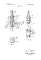
- FIG. I is a sectional view of a spark plug and adapter therefore constructed in accordance with this invention.
- FIG. 2 is an exploded perspective view of the spark plug construction of FIG. 1.
- FIG. 3 is an end view of the spark plug adapter.
- FIG. 4 illustrates a modified construction of the spark plug ofthis invention.
- FIG. 5 illustrates the spark plug construction of this invention as utilized in a multicylinder internal combustion engine.
- FIG. 6 is a modified form of the invention.
- FIG. 1 a spark plug construction 10 comprising an outer metallic plug body 11 which is provided with an external threaded connection 12 adjacent the lower end thereof.
- the spark plug body 11 is provided with an internal bore 1 3 for accommodating a conventional barrel 14 of insulating material, as for example porcelain or the like, which is held in place within the body by means ofa gland nut or plug 15 threaded to the body 11 as indicated at 16.
- the plug body 11 is provided with an internal shoulder 17 disposed intermediate the length thereof for defining a seat for a radially extending flange 14A formed integral with the porcelain barrel 14.
- the gland nut 15 is provided-with a collar 15A which firmly secures the porcelain barrel 14 in position within the body 1 1 when the gland nut 15 is threaded to the body 11.
- Extending through the porcelain barrel 14 so as to be electrically insulated from the plug body 11 is the central electrode 18 of the spark plug.
- the opposed ends of the central electrode 18 extend beyond the ends of the porcelain barrel 14.
- the upper end 18A of the electrode 18 projecting beyond the porcelain barrel I4 is provided with a threaded portion to which a terminal end cap 19 is secured.
- the upper end 18A of the central electrode 18 thus provides the terminal connector to which a distributor wire for energizing the spark plug 10 is connected.
- the other end 188 of the central electrode 18 extends beyond the porcelain barrel 14 so as to extend into the cylinder of an internal combustion engine 20 when the plug is operatively connected thereto.
- a plug adapter 21 is provided for detachably securing the spark plug body 11 and its central electrode 18 to the cylinder of an internal combustion engine 20.
- the spark plug adapter 21 comprises an adapter body 21A which is provided with a bore 22 extending therethrough.
- the lower portion 218 of the adapter body 21A is provided with a reduced portion which is externally threaded.
- The'externally threaded portion 218 of the adapter body 21A is sized to complement the internal threads of an opening formed in the head end portion of a cylinder of an internal combustion engine 20.
- the upper end portion of the adapter body 21A is provided with an internal threaded portion. 22 which is adapted to accommodate the external threaded portion 12 of the spark plug body 11.
- the spark plug body 11 and its central electrode 18 are thus readily detachably coupled to the spark plug adapter by the mating of the external thread of the plug body 11 to the internal thread 22 of the adapter body 21A.
- the grounded electrode 23 Connected to the lower end of the adapter body 21A is the grounded electrode 23 which is grounded to the adapter body 21A.
- the central electrode 18 and the electrode 23 connected to the adapter body 21A are disposed in space relationship so as to define the spark gap 24therebetween.
- the externally threaded lowerportion 21B of the adapter body 21A may be sized so as to be received within a tapped opening of a particular engine construction 20, whereas the internal threaded portion 22 of the adapter body 21A may be standardized to an optimum given size for accommodating the plug body 11 and its central electrode 18.
- the plug body 11 and its central electrode 18 may be readily utilized in varying sized engines.
- the plug body 11 and its electrode 18 may be standardized for all engines within a given range.
- the heating means 28 comprises a housing 29 connected to the adapter body 21A and which housing opens to the bore 22 extending through the adapter body 21A.
- a resistance heater 31 is connected to the inner end of the conductor 30 .
- the other end of the conductor 30 is suitably connected by a wire 32 to a source of electrical energy, e.g. the battery of the vehicle or to an auxiliary battery supplied for the purpose.
- the resistance coil of the heater 3] is preferably a low-voltage battery, as for example a 2-volt battery.
- the resistor heater 31 may be connected to one cell of a standard l2 -volt battery which constitutes the source of electrical energy for vehicles such as automobiles, trucks, planes and the like.
- the source of the electrical energy is not critical to the operation of the spark plug of this invention.
- the resistance heater 31 is thus connected in a circuit independent of the circuit utilized to energize the spark plug for defining the spark between the adjacent electrodes 18 and 23. If desired a switch means 33 may be connected in series with the resistance heater 31 energized only when the switch 33 is closed. For convenience the switch 33 may be located on the control panel of the vehicle.
- the circuit through the heating coil 31 is independent of that which serves the electrodes. Consequently the heating coil 31 is employed only when desired, and cut ofi when desired independently of the operation of the ignition system of which the spark plug constitutes a part.
- the heat generated by the resistant coil 31 is utilized to deice the electrode'and/or prevent icing during ignition and/or to maintain the electrodes dry so as to prevent shorting and/or to free the electrodes of carbon deposits formed thereon.
- FIG. 4 illustrates a modified form of the invention wherein the structure of the plug body 41 and adapter body 51 is similar to that hereinbefore described with respect to FIGS. 1 to 3, with the exception, that a plurality of heaters 52 are provided in circumferentially spaced relationship about the periphery of the adapter body 51.
- Each of the heaters 52 are constructed similar to the heater 28, described in FIGS. 1 to 3 wherein each comprises a heater housing 52A having a conductor wire 53 extending through one end thereof and which is electrically insulated from its respective housing 52A.
- a resistance heater Connected to the inner end of the respective conductor wires 53 is a resistance heater which has its other end grounded to its respective housing 52A as hereinbefore described.
- the respective conductors 53 by which current is directed to the respective resistance coil of the heaters 52 are connected in an electrical circuit in parallel by means of a conductor ring 54.
- the conductor ring 54 is provided with a substantially U-shaped cross-sectional construction in which the inner skirt portion or flange 54A thereof is provided with a plurality of cutout portions 55 adapted to make electrical contact with the conductor 53 of the respective heaters 52.
- the external skirt 54B of the conductor ring is provided with a terminal connection 56 to which a distributor wire 57 is secured for connecting the conductor ring 54 in circuit with a source of electrical energy, as for example, a battery or the like.
- a switch 58 Interposed in series between the conductor ring 54 and the battery is a switch 58 for making and breaking the circuit to the respective heaters as desired.
- spark plug construction 41 and adapter 51 are similar to that previously described with respect to FIGS. l through 3.
- the plug body 11 or 41 and its central electrode can be readily fabricated, and which plug body can be readily adapted to any particular cylinder head construction by the utilization of an appropriate sized adapter body 21 or 41.
- the spark plug body and the body adapter when fitted to a cylinder of an internal combustion 20 is such so as to prohibit any loss of compression within the cylinder as the heaters 28 or 52 are attached to the adapter body in a manner to prohibit loss of compression.
- the arrangement is such that the heater of the spark plug is energized by'a circuit independent of the circuit utilized to generate the spark between electrodes. Therefore the heaters can be actuated at will and energized only when conditions so require.
- FIG. 6 illustrates a modified form of the invention.
- a means is provided to insure the flow of fuel, i.e. gasoline or the like to the electrode of the plug.
- the spark plug is similarly constructed in a manner described with respect to FIG. 1 with-the exception that a fuel injection noule 61 is fitted to the adapter body 62.
- the injection nozzle comprises a fitting which is suitably threaded or secured to the adapter body 62.
- the inner end of the fitting is provided with an orifice opening 63 through which fuel is injected into the vicinity of the electrodes 64, 65 to prime the engine.
- the inlet 66 to the fuelinjection is suitably connected to a source of fuel, e.g.
- the gas or fuel tank 68 of the vehicle by a fuel line 67.
- a pumper or primer 69 Connected to the fuel line 67 is a pumper or primer 69 which may be of a manual actuated type.
- the actuator of the pump may comprise a button located on the dashboard or control panel of the vehicle adjacent to the switch to be actuated to energize the heater 70 of the plug 60.
- the construction of the plug 60 is similar to that described with respect to H68. 1 to 3.
- the form of the invention of HO. 4 may also be modified to include a fuel injector means as herein described with respect to H6. 6.
- the fuel injection means; as described, may be substituted for one of the heater assemblies 52.
- the regular fuel flow to the engine may not be possible. Accordingly with the fuel injection means described, the engine may be primed to thus insure the starting of the engine.
- the switch operatively connected to the heater 70 is actuated to energize the heater as hereinbefore described.
- the primer or pump 69 is actuated thereby permitting fuel to be injected through orifice 63.
- the heater 70 With the heater 70 energized the fuel is vaporized in the vicinity of the electrodes, which when actuated will thus effect prompt engine start up.
- a preheatable spark plug comprising a spark plug having a conductive plug body provided with an insulator barrel, and a central electrode extending through the insulated barrel-to protrude below a lower end of the barrel for spark formation, said conductive plug body being provided with an externally threaded lower end portion,
- a conductive adapter having a bore extending therethrough, the upper end of said adapter bore being provided with a screw thread to mesh with the threaded lower end portion of the conductive plug body and seat the conductive plug body firmly onto the adapter, said conductive adapter being provided with an electrically grounded electrode extending from a lower end over the adapter bore, with said central electrode of said spark plug being selectively sized to protrude through the bore of the adapter to terminate opposite the grounded electrode in spark-forming relationship therewith and a plurality of adapter heaters, each being formed of an electrical resistance heater, said heaters being circumferentially spaced about said adapter and electrically connected in parallel and in close heattransferring relationship with the adapter for preheating of the grounded electrode terminal and closely spaced spark plug portions to provide a highly effective preheatable spark plug.
- a preheatable spark plug comprising:
- a spark plug having a conductive body provided with an insulator barrel, and a central electrode extending through the insulated barrel to protrude below a lower end of the barrel for spark formation, said conductive plug body being provided with an externally threaded lower end portion,
- a conductive adapter having a bore extending therethrough, the upper end of said adapter bore being provided with a screw thread to mesh with the threaded lower end portion of the conductive plug body and seat the conductive plug body firmly onto the adapter, said conductive adapter being provided with an electrically grounded electrode extending from a lower end over the adapter bore, with said central electrode of said spark plug being selectively sized to protrude through the bore of the adapter to terminate opposite the grounded electrode in spark-forming relationship therewith,
- a plurality of adapter heaters circumferentially spaced about said adapter, said heaters being electrically connected in parallel, with said heaters each being formed of a heat-conductive housing extending radially from the adapter and being in close heat-transferring relationship with the adapter, said heaters being formed of electrical resistance heaters located in the housings, conductors extending radially into the housing for electrical series connection with respective individual ones of said resistance heaters for electrical preheating of the grounded electrode terminal and closely spaced spark plug portions to provide a highly effective preheatable spark plug.
- a preheatable spark plug comprising:
- said adapter body having a thread bore portion adapted to detachably receive the external threaded portion of said plug body
- said adapter body having an externally threaded portion adapted to be received in a tapped hole of a cylinder of internal combustion engines
- said central electrode and complementary electrode defining a spark gap in the connected position of said plug body and adapter body
- a plurality of heating means including housings connected to said adapter body,
- resistance heaters having one end connected to said conductors and the other end grounded through said adapter body,
- a heated adapter for accommodating a spark plug comprising an adapter body having a bore extending therethrough, said adapter being provided with means for detachably connecting said body with its bore in communication with a cylinder of an internal combustion engine and means for detachably securing the adapter body to the spark plug,
- each of said heaters including a housing extending substantially radially of said body
Landscapes
- Spark Plugs (AREA)
Abstract
This disclosure is directed to a spark plug and an adapter therefor in which the spark plug is rendered detachably connected to the adapter, and which adapter is further provided with one or more means for heating the electrodes of the plugs to facilitate the starting of internal combustion engines in cold and/or moist weather.
Description
United States Patent Robert R'eichhelm Wallingford. Conn. 796,745
Feb. 5, 1969 June 29, 197i Burnham Corporation lrvington, N.Y. I
inventor Appl. No. Filed Patented [73] Assignee [54] SPARK PLUG AND HEATED ADAPTOR THEREFOR 5 Claims, 6 Drawing Figs.
u.s.c1 123/169 PB 1111. c1 F02p 13/00 FieldoiSearch ..123/32 SPJ. 143.145.145 A; [69 CR. 169 DW. 169 E.
169 C. I69 11-:. iPRA. 1PR ,1 9 v; 219/385 Primary Examiner-Laurence M. Goodridge Attorney-Arthur T. Fattibene ABSTRACT: This disclosure is directed to a spark plug and an adapter therefor in which the spark plug is rendered detachably connected to the adapter, and which adapter is further provided with one or more means for heating the electrodes of the plugs to facilitate the starting of internal combustion engines in cold and/or moist weather.
PATENTEUJUHZQIQYI 3,589,348
sum 1 [IF 2 INVENTOR. ROBERT REICHHtLM aw viw ATTORNEY- PATENTEDYJUNZSIQYI 3589.348
In the past there have been many efforts to overcome the above-noted problems. These efforts included the provision of covers or shields to protect spark plugs against the weather. However these efforts have proven to be either impractical, ineffectual, or of nominal effect over a minimal period oftime. In extremely cold climates the efi'orts to overcome icing consisted of maintaining the entire engine warm by an external heating source and/or removing the battery and storing the battery in a warm place until it was desired to start an engine. Heaters have also been placed in the crankcase of the engine to maintain the lubricating oil fluent in an effort to minimize the drain on a battery when starting in cold weather. However these methods are impractical as frequently external heat sources and or warm storage areas are not readily available, e.g. in open country or on long trips away from a home base. In such instances starting of an engine is virtually impossible.
In my prior US. Pat. No. 2,889,440 it was disclosed that the problem of starting engines having wet, cold and/or fouled plugs was enhanced by providing a spark plug with a heater which was separately energized to heat, dry or clear fouled plugs. This invention therefore constitutes an improvement in the heated spark plug concept disclosed in my above mentioned prior patent.
OBJECTS An object of this invention is to provide an improved heated plug which is relatively simple in construction, inexpensive to manufacture, and positive in operation.
Another object is to provide a spark plug and a readily detachable adapter which can be readily applied to any internal combustion engine.
Another object is to provide a spark plug construction which can be readily standardized for use on any sized engine.
Another object is to provide an adapter for detachably connecting a spark plug of a particular standard to any particular engine.
Another object is to provide a spark plug and an adapter therefore whereby the spark plug may be rendered usable on all size engines with the utilization of the proper adapter.
Another object is to provide the spark plug adapter having one or more heaters which are energized independently of the spark plug.
BRIEF SUMMARY OF INVENTION The foregoing objects and other features and advantages are attained by a spark plug comprising a plug body having a central electrode electrically insulated therefrom and an adapter for detachably securing the spark plug body so that the central electrode is exposed to the fuel being injected or introduced into the cylinder of an internal combustion engine. Both the spark plug body and adapter are provided with complementary means to detachably connect the spark plug body and its central electrode to the adapter. The adapter has grounded thereto an electrode which is spaced from the central electrode in the connected position to define the spark gap.
Means for heating the electrodes are secured to the adapter to heat the electrode so as to prohibit icing and/or to maintain the electrodes dry and free of carbon deposits. The heating means are operatively connected in circuit to a suitable source of electrical energy and a switch means may be interposed in the heater circuit so that the heater may be energized at will when the switch is actuated. The heating means comprises one or more heaters circumferentially spaced about the adapter. When more than one heaters are employed, the respective heaters are connected in circuit by a conductive ring.
FEATURES A feature of this invention resides in the provision of a spark plug body having a central electrode which is detachably connected to an adapter by which the plug is detachably connected to an internal combustion engine.
Another feature resides in the provision of one or more heaters connected to the adapter for heating, drying or defouling the electrodes.
Another feature resides in the provision of a spark plug having means for heating the electrodes of the plug in a positive manner to facilitate starting of an internal combustion engine in cold and/or wet weather.
Another feature resides in the provision of a spark plug and heater adapter constructed and arranged so that in operation compression of the engine can be maintained.
Another feature resides in the provision of a spark plug and heater adapter which is constructed and arranged to inject a supply of priming fuel in the vicinity of the heated electrodes to assure ignition in cold and/or damp weather. In the drawings:
FIG. I is a sectional view of a spark plug and adapter therefore constructed in accordance with this invention.
FIG. 2 is an exploded perspective view of the spark plug construction of FIG. 1.
FIG. 3 is an end view of the spark plug adapter.
FIG. 4 illustrates a modified construction of the spark plug ofthis invention.
FIG. 5 illustrates the spark plug construction of this invention as utilized in a multicylinder internal combustion engine.
FIG. 6 is a modified form of the invention.
Referring to the drawings there is illustrated in FIG. 1 a spark plug construction 10 comprising an outer metallic plug body 11 which is provided with an external threaded connection 12 adjacent the lower end thereof. The spark plug body 11 is provided with an internal bore 1 3 for accommodating a conventional barrel 14 of insulating material, as for example porcelain or the like, which is held in place within the body by means ofa gland nut or plug 15 threaded to the body 11 as indicated at 16. As shown the plug body 11 is provided with an internal shoulder 17 disposed intermediate the length thereof for defining a seat for a radially extending flange 14A formed integral with the porcelain barrel 14. The gland nut 15 is provided-with a collar 15A which firmly secures the porcelain barrel 14 in position within the body 1 1 when the gland nut 15 is threaded to the body 11. Extending through the porcelain barrel 14 so as to be electrically insulated from the plug body 11 is the central electrode 18 of the spark plug. As shown the opposed ends of the central electrode 18 extend beyond the ends of the porcelain barrel 14. The upper end 18A of the electrode 18 projecting beyond the porcelain barrel I4 is provided with a threaded portion to which a terminal end cap 19 is secured. The upper end 18A of the central electrode 18 thus provides the terminal connector to which a distributor wire for energizing the spark plug 10 is connected.
The other end 188 of the central electrode 18 extends beyond the porcelain barrel 14 so as to extend into the cylinder of an internal combustion engine 20 when the plug is operatively connected thereto.
A plug adapter 21 is provided for detachably securing the spark plug body 11 and its central electrode 18 to the cylinder of an internal combustion engine 20. As shown the spark plug adapter 21 comprises an adapter body 21A which is provided with a bore 22 extending therethrough. As shown the lower portion 218 of the adapter body 21A is provided with a reduced portion which is externally threaded. The'externally threaded portion 218 of the adapter body 21A is sized to complement the internal threads of an opening formed in the head end portion of a cylinder of an internal combustion engine 20. The upper end portion of the adapter body 21A is provided with an internal threaded portion. 22 which is adapted to accommodate the external threaded portion 12 of the spark plug body 11. The spark plug body 11 and its central electrode 18 are thus readily detachably coupled to the spark plug adapter by the mating of the external thread of the plug body 11 to the internal thread 22 of the adapter body 21A.
Connected to the lower end of the adapter body 21A is the grounded electrode 23 which is grounded to the adapter body 21A. The central electrode 18 and the electrode 23 connected to the adapter body 21A are disposed in space relationship so as to define the spark gap 24therebetween.
With the construction described it will be apparent that the externally threaded lowerportion 21B of the adapter body 21A may be sized so as to be received within a tapped opening of a particular engine construction 20, whereas the internal threaded portion 22 of the adapter body 21A may be standardized to an optimum given size for accommodating the plug body 11 and its central electrode 18. With the construction described it will be readily apparent that by merely altering the dimension of external threaded portion 218 of a particular adapter, the plug body 11 and its central electrode 18 may be readily utilized in varying sized engines. Thus the plug body 11 and its electrode 18 may be standardized for all engines within a given range.
To prohibit icing of the electrodes and/or maintaining the electrodes dry and free of carbon fouling, a heating means 28 is provided. As best seen in FIG. 1, the heating means 28 comprises a housing 29 connected to the adapter body 21A and which housing opens to the bore 22 extending through the adapter body 21A. A conductor wire 30, suitably insulated from the housing 29, extends thereinto. Connected to the inner end of the conductor 30 is a resistance heater 31, as for example a coil heater, which has its other end grounded, preferably to the heater housing 29 and through the adapter body 21A to the engine 20. The other end of the conductor 30 is suitably connected by a wire 32 to a source of electrical energy, e.g. the battery of the vehicle or to an auxiliary battery supplied for the purpose. The resistance coil of the heater 3] is preferably a low-voltage battery, as for example a 2-volt battery. Alternately the resistor heater 31 may be connected to one cell of a standard l2 -volt battery which constitutes the source of electrical energy for vehicles such as automobiles, trucks, planes and the like. However it will be understood that the source of the electrical energy is not critical to the operation of the spark plug of this invention.
The resistance heater 31 is thus connected in a circuit independent of the circuit utilized to energize the spark plug for defining the spark between the adjacent electrodes 18 and 23. If desired a switch means 33 may be connected in series with the resistance heater 31 energized only when the switch 33 is closed. For convenience the switch 33 may be located on the control panel of the vehicle.
In operation it will be apparent that the utilization of the plug body 11 and adapter 21 in an internal combustion engine will enhance its starting in'cold and/or damp weather. With an internal combustion engine 20 provided with at least one plug and adapter 10, as described, in each bank of cylinders, the engine can be readily started in wet or cold weather merely by closing the switch 33 for a time sufficient to energize the heater 3]. The heat generated thereby is directed toward the electrodes 18, 23 to heat the same and thereby prohibit the formation of icing and/0r drying the electrodes so that a positive spark is generated across the gap 24 and between the electrodes when the spark plug is actuated as by turning on of the ignition system of the vehicle to energize electrodes of the plug. As described, the circuit through the heating coil 31 is independent of that which serves the electrodes. Consequently the heating coil 31 is employed only when desired, and cut ofi when desired independently of the operation of the ignition system of which the spark plug constitutes a part. The heat generated by the resistant coil 31 is utilized to deice the electrode'and/or prevent icing during ignition and/or to maintain the electrodes dry so as to prevent shorting and/or to free the electrodes of carbon deposits formed thereon. By maintaining the tips of the electrodes 18, 23 free of ice, moisture and/or carbon deposits, a positive spark is assured and positive ignition of the fuel is attained with a minimum of drain on the battery.
FIG. 4 illustrates a modified form of the invention wherein the structure of the plug body 41 and adapter body 51 is similar to that hereinbefore described with respect to FIGS. 1 to 3, with the exception, that a plurality of heaters 52 are provided in circumferentially spaced relationship about the periphery of the adapter body 51. Each of the heaters 52 are constructed similar to the heater 28, described in FIGS. 1 to 3 wherein each comprises a heater housing 52A having a conductor wire 53 extending through one end thereof and which is electrically insulated from its respective housing 52A. Connected to the inner end of the respective conductor wires 53 is a resistance heater which has its other end grounded to its respective housing 52A as hereinbefore described. The respective conductors 53 by which current is directed to the respective resistance coil of the heaters 52 are connected in an electrical circuit in parallel by means of a conductor ring 54. As shown in H6. 4, the conductor ring 54 is provided with a substantially U-shaped cross-sectional construction in which the inner skirt portion or flange 54A thereof is provided with a plurality of cutout portions 55 adapted to make electrical contact with the conductor 53 of the respective heaters 52. The external skirt 54B of the conductor ring is provided with a terminal connection 56 to which a distributor wire 57 is secured for connecting the conductor ring 54 in circuit with a source of electrical energy, as for example, a battery or the like. Interposed in series between the conductor ring 54 and the battery is a switch 58 for making and breaking the circuit to the respective heaters as desired.
In operation, and in all other respects the spark plug construction 41 and adapter 51 therefore as described in FIG. 4, are similar to that previously described with respect to FIGS. l through 3.
With the construction described it will be noted that the plug body 11 or 41 and its central electrode can be readily fabricated, and which plug body can be readily adapted to any particular cylinder head construction by the utilization of an appropriate sized adapter body 21 or 41. With the construction disclosed it will be noted that assembled, the spark plug body and the body adapter when fitted to a cylinder of an internal combustion 20 is such so as to prohibit any loss of compression within the cylinder as the heaters 28 or 52 are attached to the adapter body in a manner to prohibit loss of compression. Also the arrangement is such that the heater of the spark plug is energized by'a circuit independent of the circuit utilized to generate the spark between electrodes. Therefore the heaters can be actuated at will and energized only when conditions so require.
FIG. 6 illustrates a modified form of the invention. In this form of the invention a means is provided to insure the flow of fuel, i.e. gasoline or the like to the electrode of the plug. As shown in FIG. 6, the spark plug is similarly constructed in a manner described with respect to FIG. 1 with-the exception that a fuel injection noule 61 is fitted to the adapter body 62. The injection nozzle comprises a fitting which is suitably threaded or secured to the adapter body 62. The inner end of the fitting is provided with an orifice opening 63 through which fuel is injected into the vicinity of the electrodes 64, 65 to prime the engine. It will be understood that the inlet 66 to the fuelinjection is suitably connected to a source of fuel, e.g. the gas or fuel tank 68 of the vehicle by a fuel line 67. Connected to the fuel line 67 is a pumper or primer 69 which may be of a manual actuated type. The actuator of the pump may comprise a button located on the dashboard or control panel of the vehicle adjacent to the switch to be actuated to energize the heater 70 of the plug 60. In all other respects the construction of the plug 60 is similar to that described with respect to H68. 1 to 3.
The form of the invention of HO. 4 may also be modified to include a fuel injector means as herein described with respect to H6. 6. The fuel injection means; as described, may be substituted for one of the heater assemblies 52.
At very low temperature the regular fuel flow to the engine may not be possible. Accordingly with the fuel injection means described, the engine may be primed to thus insure the starting of the engine. I
With the construction described with respect to FIG. 6, the switch operatively connected to the heater 70 is actuated to energize the heater as hereinbefore described. With the heater 70 energized, the primer or pump 69 is actuated thereby permitting fuel to be injected through orifice 63. With the heater 70 energized the fuel is vaporized in the vicinity of the electrodes, which when actuated will thus effect prompt engine start up.
While the instant invention has been described and illustrated with respect to several embodiments thereof it will be readily understood and appreciated that variations and modifications may be made without departing from the spirit or scope of the invention.
What I claim is:
l. A preheatable spark plug comprising a spark plug having a conductive plug body provided with an insulator barrel, and a central electrode extending through the insulated barrel-to protrude below a lower end of the barrel for spark formation, said conductive plug body being provided with an externally threaded lower end portion,
a conductive adapter having a bore extending therethrough, the upper end of said adapter bore being provided with a screw thread to mesh with the threaded lower end portion of the conductive plug body and seat the conductive plug body firmly onto the adapter, said conductive adapter being provided with an electrically grounded electrode extending from a lower end over the adapter bore, with said central electrode of said spark plug being selectively sized to protrude through the bore of the adapter to terminate opposite the grounded electrode in spark-forming relationship therewith and a plurality of adapter heaters, each being formed of an electrical resistance heater, said heaters being circumferentially spaced about said adapter and electrically connected in parallel and in close heattransferring relationship with the adapter for preheating of the grounded electrode terminal and closely spaced spark plug portions to provide a highly effective preheatable spark plug.
2. A preheatable spark plug comprising:
a spark plug having a conductive body provided with an insulator barrel, and a central electrode extending through the insulated barrel to protrude below a lower end of the barrel for spark formation, said conductive plug body being provided with an externally threaded lower end portion,
a conductive adapter having a bore extending therethrough, the upper end of said adapter bore being provided with a screw thread to mesh with the threaded lower end portion of the conductive plug body and seat the conductive plug body firmly onto the adapter, said conductive adapter being provided with an electrically grounded electrode extending from a lower end over the adapter bore, with said central electrode of said spark plug being selectively sized to protrude through the bore of the adapter to terminate opposite the grounded electrode in spark-forming relationship therewith,
a plurality of adapter heaters circumferentially spaced about said adapter, said heaters being electrically connected in parallel, with said heaters each being formed of a heat-conductive housing extending radially from the adapter and being in close heat-transferring relationship with the adapter, said heaters being formed of electrical resistance heaters located in the housings, conductors extending radially into the housing for electrical series connection with respective individual ones of said resistance heaters for electrical preheating of the grounded electrode terminal and closely spaced spark plug portions to provide a highly effective preheatable spark plug.
3. The preheatable spark plug as claimed in claim 2 and further including a conducting ring electrically connecting each of said heaters in parallel.
4. A preheatable spark plug comprising:
a cylindrical plug body having a lower end portion provided with external threads,
an insulated barrel portion extended through said plug body,
a central electrode extended through said insulated barrel portion with the ends of said central electrode extending beyond the respective ends of said barrel portion,
means connected to the upper end of said central electrodes defining a terminal connector,
an adapter body,
said adapter body having a thread bore portion adapted to detachably receive the external threaded portion of said plug body,
said adapter body having an externally threaded portion adapted to be received in a tapped hole of a cylinder of internal combustion engines,
said externally threaded portion of the adapter body having the same size as the threaded lower end portion of said plug body,
a complementary electrode connected to said adapter body,
said central electrode and complementary electrode defining a spark gap in the connected position of said plug body and adapter body,
a plurality of heating means including housings connected to said adapter body,
electrical conductors adapted to be connected in circuit to a source of electrical energy extending into said housings,
resistance heaters having one end connected to said conductors and the other end grounded through said adapter body,
and a conducting ring electrically connecting said heating means in circuit.
5. A heated adapter for accommodating a spark plug comprising an adapter body having a bore extending therethrough, said adapter being provided with means for detachably connecting said body with its bore in communication with a cylinder of an internal combustion engine and means for detachably securing the adapter body to the spark plug,
a plurality of heaters circumferentially spaced about said adapter body,
each of said heaters including a housing extending substantially radially of said body,
a resistance heater disposed in each of said housings,
a conductor connected to each of said resistance heaters and projecting outwardly of the respective housings,
and a conductor ring connecting each of said conductors in a circuit to a source of electrical energy.
Claims (5)
1. A preheatable spark plug comprising a spark plug having a conductive plug body provided with an insulator barrel, and a central electrode extending through the insulated barrel to protrude below a lower end of the barrel for spark formation, said conductive plug body being provided with an externally threaded lower end portion, a conductive adapter having a bore extending therethrough, the upper end of said adapter bore being provided with a screw thread to mesh with the threaded lower end portion of the conductive plug Body and seat the conductive plug body firmly onto the adapter, said conductive adapter being provided with an electrically grounded electrode extending from a lower end over the adapter bore, with said central electrode of said spark plug being selectively sized to protrude through the bore of the adapter to terminate opposite the grounded electrode in spark-forming relationship therewith and a plurality of adapter heaters, each being formed of an electrical resistance heater, said heaters being circumferentially spaced about said adapter and electrically connected in parallel and in close heattransferring relationship with the adapter for preheating of the grounded electrode terminal and closely spaced spark plug portions to provide a highly effective preheatable spark plug.
2. A preheatable spark plug comprising: a spark plug having a conductive body provided with an insulator barrel, and a central electrode extending through the insulated barrel to protrude below a lower end of the barrel for spark formation, said conductive plug body being provided with an externally threaded lower end portion, a conductive adapter having a bore extending therethrough, the upper end of said adapter bore being provided with a screw thread to mesh with the threaded lower end portion of the conductive plug body and seat the conductive plug body firmly onto the adapter, said conductive adapter being provided with an electrically grounded electrode extending from a lower end over the adapter bore, with said central electrode of said spark plug being selectively sized to protrude through the bore of the adapter to terminate opposite the grounded electrode in spark-forming relationship therewith, a plurality of adapter heaters circumferentially spaced about said adapter, said heaters being electrically connected in parallel, with said heaters each being formed of a heat-conductive housing extending radially from the adapter and being in close heat-transferring relationship with the adapter, said heaters being formed of electrical resistance heaters located in the housings, conductors extending radially into the housing for electrical series connection with respective individual ones of said resistance heaters for electrical preheating of the grounded electrode terminal and closely spaced spark plug portions to provide a highly effective preheatable spark plug.
3. The preheatable spark plug as claimed in claim 2 and further including a conducting ring electrically connecting each of said heaters in parallel.
4. A preheatable spark plug comprising: a cylindrical plug body having a lower end portion provided with external threads, an insulated barrel portion extended through said plug body, a central electrode extended through said insulated barrel portion with the ends of said central electrode extending beyond the respective ends of said barrel portion, means connected to the upper end of said central electrodes defining a terminal connector, an adapter body, said adapter body having a thread bore portion adapted to detachably receive the external threaded portion of said plug body, said adapter body having an externally threaded portion adapted to be received in a tapped hole of a cylinder of internal combustion engines, said externally threaded portion of the adapter body having the same size as the threaded lower end portion of said plug body, a complementary electrode connected to said adapter body, said central electrode and complementary electrode defining a spark gap in the connected position of said plug body and adapter body, a plurality of heating means including housings connected to said adapter body, electrical conductors adapted to be connected in circuit to a source of electrical energy extending into said housings, resistance heaters having one end connected to said conductors and the other end grounded through said adapter body, and a conducting ring electrically connecting saiD heating means in circuit.
5. A heated adapter for accommodating a spark plug comprising an adapter body having a bore extending therethrough, said adapter being provided with means for detachably connecting said body with its bore in communication with a cylinder of an internal combustion engine and means for detachably securing the adapter body to the spark plug, a plurality of heaters circumferentially spaced about said adapter body, each of said heaters including a housing extending substantially radially of said body, a resistance heater disposed in each of said housings, a conductor connected to each of said resistance heaters and projecting outwardly of the respective housings, and a conductor ring connecting each of said conductors in a circuit to a source of electrical energy.
Applications Claiming Priority (1)
| Application Number | Priority Date | Filing Date | Title |
|---|---|---|---|
| US79674569A | 1969-02-05 | 1969-02-05 |
Publications (1)
| Publication Number | Publication Date |
|---|---|
| US3589348A true US3589348A (en) | 1971-06-29 |
Family
ID=25168949
Family Applications (1)
| Application Number | Title | Priority Date | Filing Date |
|---|---|---|---|
| US796745A Expired - Lifetime US3589348A (en) | 1969-02-05 | 1969-02-05 | Spark plug and heated adaptor therefor |
Country Status (1)
| Country | Link |
|---|---|
| US (1) | US3589348A (en) |
Cited By (45)
| Publication number | Priority date | Publication date | Assignee | Title |
|---|---|---|---|---|
| DE2417968A1 (en) * | 1973-04-18 | 1974-11-07 | Champion Spark Plug Co | SPARK PLUG WITH GLOW PLUG |
| US4903676A (en) * | 1987-08-28 | 1990-02-27 | Saab-Scania Aktiebolag | Method and arrangement for improving the starting ability of an internal combustion engine during an engine start |
| US4947810A (en) * | 1987-08-28 | 1990-08-14 | Saab-Scania Aktiebolag | Method and arrangement for improving the starting ability of an internal combustion engine, when an attempt to start the engine has failed |
| US5297519A (en) * | 1992-02-19 | 1994-03-29 | Syilvan Simons | Method and apparatus for direct fuel injection in an internal combustion engine |
| RU2213401C2 (en) * | 2001-04-13 | 2003-09-27 | Фирсов Владимир Михайлович | Spark plug |
| US20040084001A1 (en) * | 2002-11-01 | 2004-05-06 | Lipski Mark C. | Multiple sparking ignition device |
| US7073471B1 (en) * | 2005-09-27 | 2006-07-11 | Gregory Damian Mead | Apparatus and method for improving engine performance |
| US20070119421A1 (en) * | 2005-11-30 | 2007-05-31 | Lewis Donald J | System and method for compensation of fuel injector limits |
| US20070119412A1 (en) * | 2005-11-30 | 2007-05-31 | Leone Thomas G | Engine with two port fuel injectors |
| US20070119394A1 (en) * | 2005-11-30 | 2007-05-31 | Leone Thomas G | Fuel mass control for ethanol direct injection plus gasoline port fuel injection |
| US20070119416A1 (en) * | 2005-11-30 | 2007-05-31 | Boyarski Nicholas J | System for fuel vapor purging |
| US20070119415A1 (en) * | 2005-11-30 | 2007-05-31 | Lewis Donald J | System and method for engine air-fuel ratio control |
| US20070119413A1 (en) * | 2005-11-30 | 2007-05-31 | Lewis Donald J | Event based engine control system and method |
| US20070119391A1 (en) * | 2005-11-30 | 2007-05-31 | Marcus Fried | Control for alcohol/water/gasoline injection |
| US7255080B1 (en) * | 2006-03-17 | 2007-08-14 | Ford Global Technologies, Llc | Spark plug heating for a spark ignited engine |
| US20070215130A1 (en) * | 2006-03-17 | 2007-09-20 | Michael Shelby | Spark control for improved engine operation |
| US20070215069A1 (en) * | 2006-03-17 | 2007-09-20 | Leone Thomas G | Control for knock suppression fluid separator in a motor vehicle |
| US20070215111A1 (en) * | 2006-03-17 | 2007-09-20 | Gopichandra Surnilla | System and method for reducing knock and preignition in an internal combustion engine |
| US20070215102A1 (en) * | 2006-03-17 | 2007-09-20 | Russell John D | First and second spark plugs for improved combustion control |
| US20070215071A1 (en) * | 2006-03-17 | 2007-09-20 | Mark Dearth | Apparatus with mixed fuel separator and method of separating a mixed fuel |
| US20070215104A1 (en) * | 2006-03-17 | 2007-09-20 | Stephen Hahn | Combustion control system for an engine utilizing a first fuel and a second fuel |
| US20070219674A1 (en) * | 2006-03-17 | 2007-09-20 | Leone Thomas G | Control of peak engine output in an engine with a knock suppression fluid |
| US20070215101A1 (en) * | 2006-03-17 | 2007-09-20 | Russell John D | First and second spark plugs for improved combustion control |
| US20070215072A1 (en) * | 2006-03-17 | 2007-09-20 | Mark Dearth | Apparatus with mixed fuel separator and method of separating a mixed fuel |
| US20070289573A1 (en) * | 2005-11-30 | 2007-12-20 | Ford Global Technologies, Llc | Warm Up Strategy for Ethanol Direct Injection Plus Gasoline Port Fuel Injection |
| US20070295307A1 (en) * | 2005-11-30 | 2007-12-27 | Ford Global Technologies, Llc | System and Method for Engine with Fuel Vapor Purging |
| US20080017171A1 (en) * | 2006-07-24 | 2008-01-24 | Ford Global Technologies, Llc | Approach for Reducing Injector Fouling and Thermal Degradation for a Multi-Injector Engine System |
| US20080035106A1 (en) * | 2006-08-11 | 2008-02-14 | Stein Robert A | Direct Injection Alcohol Engine with Boost and Spark Control |
| US7406947B2 (en) | 2005-11-30 | 2008-08-05 | Ford Global Technologies, Llc | System and method for tip-in knock compensation |
| US7412966B2 (en) | 2005-11-30 | 2008-08-19 | Ford Global Technologies, Llc | Engine output control system and method |
| US7426908B2 (en) | 2006-08-11 | 2008-09-23 | Ford Global Technologies, Llc | Direct injection alcohol engine with variable injection timing |
| US7428895B2 (en) | 2005-11-30 | 2008-09-30 | Ford Global Technologies, Llc | Purge system for ethanol direct injection plus gas port fuel injection |
| US20080288158A1 (en) * | 2006-03-17 | 2008-11-20 | Ford Global Technologies, Llc | Control for knock suppression fluid separator in a motor vehicle |
| US7461628B2 (en) | 2006-12-01 | 2008-12-09 | Ford Global Technologies, Llc | Multiple combustion mode engine using direct alcohol injection |
| US20090038585A1 (en) * | 2007-08-10 | 2009-02-12 | Ford Global Technologies, Llc | Hybrid Vehicle Propulsion System Utilizing Knock Suppression |
| US20090038586A1 (en) * | 2007-08-10 | 2009-02-12 | Ford Global Technologies, Llc | Hybrid Vehicle Propulsion System Utilizing Knock Suppression |
| US20090178654A1 (en) * | 2008-01-16 | 2009-07-16 | Ford Global Technologies, Llc | Ethanol Separation Using Air from Turbo Compressor |
| US7581528B2 (en) | 2006-03-17 | 2009-09-01 | Ford Global Technologies, Llc | Control strategy for engine employng multiple injection types |
| US7665428B2 (en) | 2006-03-17 | 2010-02-23 | Ford Global Technologies, Llc | Apparatus with mixed fuel separator and method of separating a mixed fuel |
| US7730872B2 (en) | 2005-11-30 | 2010-06-08 | Ford Global Technologies, Llc | Engine with water and/or ethanol direct injection plus gas port fuel injectors |
| US7845315B2 (en) | 2008-05-08 | 2010-12-07 | Ford Global Technologies, Llc | On-board water addition for fuel separation system |
| US20110139107A1 (en) * | 2009-12-15 | 2011-06-16 | John Burrows | Spark ignition device for an internal combustion engine and central electrode assembly therefor |
| US7971567B2 (en) | 2007-10-12 | 2011-07-05 | Ford Global Technologies, Llc | Directly injected internal combustion engine system |
| US8118009B2 (en) | 2007-12-12 | 2012-02-21 | Ford Global Technologies, Llc | On-board fuel vapor separation for multi-fuel vehicle |
| US8550058B2 (en) | 2007-12-21 | 2013-10-08 | Ford Global Technologies, Llc | Fuel rail assembly including fuel separation membrane |
Citations (5)
| Publication number | Priority date | Publication date | Assignee | Title |
|---|---|---|---|---|
| US1364262A (en) * | 1920-01-30 | 1921-01-04 | Edward C Theis | Spark-plug |
| US1377352A (en) * | 1921-05-10 | Chester f | ||
| US1430964A (en) * | 1921-03-17 | 1922-10-03 | Electric Heated Spark Plug Co | Spark plug |
| US1432214A (en) * | 1918-03-15 | 1922-10-17 | Elmer A Sperry | Fuel injecting and igniting means for oil engines |
| US1596240A (en) * | 1924-09-08 | 1926-08-17 | Myron J Dikeman | Ignition flash plug |
-
1969
- 1969-02-05 US US796745A patent/US3589348A/en not_active Expired - Lifetime
Patent Citations (5)
| Publication number | Priority date | Publication date | Assignee | Title |
|---|---|---|---|---|
| US1377352A (en) * | 1921-05-10 | Chester f | ||
| US1432214A (en) * | 1918-03-15 | 1922-10-17 | Elmer A Sperry | Fuel injecting and igniting means for oil engines |
| US1364262A (en) * | 1920-01-30 | 1921-01-04 | Edward C Theis | Spark-plug |
| US1430964A (en) * | 1921-03-17 | 1922-10-03 | Electric Heated Spark Plug Co | Spark plug |
| US1596240A (en) * | 1924-09-08 | 1926-08-17 | Myron J Dikeman | Ignition flash plug |
Cited By (94)
| Publication number | Priority date | Publication date | Assignee | Title |
|---|---|---|---|---|
| DE2417968A1 (en) * | 1973-04-18 | 1974-11-07 | Champion Spark Plug Co | SPARK PLUG WITH GLOW PLUG |
| US3851637A (en) * | 1973-04-18 | 1974-12-03 | Champion Spark Plug Co | Spark plug with glow plug |
| US4903676A (en) * | 1987-08-28 | 1990-02-27 | Saab-Scania Aktiebolag | Method and arrangement for improving the starting ability of an internal combustion engine during an engine start |
| US4947810A (en) * | 1987-08-28 | 1990-08-14 | Saab-Scania Aktiebolag | Method and arrangement for improving the starting ability of an internal combustion engine, when an attempt to start the engine has failed |
| US5297519A (en) * | 1992-02-19 | 1994-03-29 | Syilvan Simons | Method and apparatus for direct fuel injection in an internal combustion engine |
| RU2213401C2 (en) * | 2001-04-13 | 2003-09-27 | Фирсов Владимир Михайлович | Spark plug |
| US20040084001A1 (en) * | 2002-11-01 | 2004-05-06 | Lipski Mark C. | Multiple sparking ignition device |
| US6807933B2 (en) * | 2002-11-01 | 2004-10-26 | Mark C. Lipski | Multiple sparking ignition device |
| US7073471B1 (en) * | 2005-09-27 | 2006-07-11 | Gregory Damian Mead | Apparatus and method for improving engine performance |
| US8132555B2 (en) | 2005-11-30 | 2012-03-13 | Ford Global Technologies, Llc | Event based engine control system and method |
| US7640914B2 (en) | 2005-11-30 | 2010-01-05 | Ford Global Technologies, Llc | Engine output control system and method |
| US20070119394A1 (en) * | 2005-11-30 | 2007-05-31 | Leone Thomas G | Fuel mass control for ethanol direct injection plus gasoline port fuel injection |
| US20070119416A1 (en) * | 2005-11-30 | 2007-05-31 | Boyarski Nicholas J | System for fuel vapor purging |
| US20070119415A1 (en) * | 2005-11-30 | 2007-05-31 | Lewis Donald J | System and method for engine air-fuel ratio control |
| US20070119413A1 (en) * | 2005-11-30 | 2007-05-31 | Lewis Donald J | Event based engine control system and method |
| US20070119391A1 (en) * | 2005-11-30 | 2007-05-31 | Marcus Fried | Control for alcohol/water/gasoline injection |
| US8434431B2 (en) | 2005-11-30 | 2013-05-07 | Ford Global Technologies, Llc | Control for alcohol/water/gasoline injection |
| US8393312B2 (en) | 2005-11-30 | 2013-03-12 | Ford Global Technologies, Llc | Event based engine control system and method |
| US7426925B2 (en) | 2005-11-30 | 2008-09-23 | Ford Global Technologies, Llc | Warm up strategy for ethanol direct injection plus gasoline port fuel injection |
| US7877189B2 (en) | 2005-11-30 | 2011-01-25 | Ford Global Technologies, Llc | Fuel mass control for ethanol direct injection plus gasoline port fuel injection |
| US7730872B2 (en) | 2005-11-30 | 2010-06-08 | Ford Global Technologies, Llc | Engine with water and/or ethanol direct injection plus gas port fuel injectors |
| US7721710B2 (en) | 2005-11-30 | 2010-05-25 | Ford Global Technologies, Llc | Warm up strategy for ethanol direct injection plus gasoline port fuel injection |
| US7694666B2 (en) | 2005-11-30 | 2010-04-13 | Ford Global Technologies, Llc | System and method for tip-in knock compensation |
| US7647916B2 (en) | 2005-11-30 | 2010-01-19 | Ford Global Technologies, Llc | Engine with two port fuel injectors |
| US20070119412A1 (en) * | 2005-11-30 | 2007-05-31 | Leone Thomas G | Engine with two port fuel injectors |
| US7640912B2 (en) | 2005-11-30 | 2010-01-05 | Ford Global Technologies, Llc | System and method for engine air-fuel ratio control |
| US7594498B2 (en) | 2005-11-30 | 2009-09-29 | Ford Global Technologies, Llc | System and method for compensation of fuel injector limits |
| US20070289573A1 (en) * | 2005-11-30 | 2007-12-20 | Ford Global Technologies, Llc | Warm Up Strategy for Ethanol Direct Injection Plus Gasoline Port Fuel Injection |
| US20070295307A1 (en) * | 2005-11-30 | 2007-12-27 | Ford Global Technologies, Llc | System and Method for Engine with Fuel Vapor Purging |
| US7584740B2 (en) | 2005-11-30 | 2009-09-08 | Ford Global Technologies, Llc | Engine system for multi-fluid operation |
| US20070119421A1 (en) * | 2005-11-30 | 2007-05-31 | Lewis Donald J | System and method for compensation of fuel injector limits |
| US7357101B2 (en) | 2005-11-30 | 2008-04-15 | Ford Global Technologies, Llc | Engine system for multi-fluid operation |
| US20090070021A1 (en) * | 2005-11-30 | 2009-03-12 | Ford Global Technologies, Llc | Warm Up Strategy for Ethanol Direct Injection Plus Gasoline Port Fuel Injection |
| US7406947B2 (en) | 2005-11-30 | 2008-08-05 | Ford Global Technologies, Llc | System and method for tip-in knock compensation |
| US7412966B2 (en) | 2005-11-30 | 2008-08-19 | Ford Global Technologies, Llc | Engine output control system and method |
| US20080210207A1 (en) * | 2005-11-30 | 2008-09-04 | Ford Global Technologies, Llc | Engine System for Multi-Fluid Operation |
| US7424881B2 (en) | 2005-11-30 | 2008-09-16 | Ford Global Technologies, Llc | System and method for engine with fuel vapor purging |
| US7428895B2 (en) | 2005-11-30 | 2008-09-30 | Ford Global Technologies, Llc | Purge system for ethanol direct injection plus gas port fuel injection |
| US7533651B2 (en) | 2006-03-17 | 2009-05-19 | Ford Global Technologies, Llc | System and method for reducing knock and preignition in an internal combustion engine |
| US7779813B2 (en) | 2006-03-17 | 2010-08-24 | Ford Global Technologies, Llc | Combustion control system for an engine utilizing a first fuel and a second fuel |
| US7426907B2 (en) | 2006-03-17 | 2008-09-23 | Ford Global Technologies, Llc | Apparatus with mixed fuel separator and method of separating a mixed fuel |
| US20080288158A1 (en) * | 2006-03-17 | 2008-11-20 | Ford Global Technologies, Llc | Control for knock suppression fluid separator in a motor vehicle |
| US7255080B1 (en) * | 2006-03-17 | 2007-08-14 | Ford Global Technologies, Llc | Spark plug heating for a spark ignited engine |
| US20070215130A1 (en) * | 2006-03-17 | 2007-09-20 | Michael Shelby | Spark control for improved engine operation |
| US8267074B2 (en) | 2006-03-17 | 2012-09-18 | Ford Global Technologies, Llc | Control for knock suppression fluid separator in a motor vehicle |
| US7389751B2 (en) | 2006-03-17 | 2008-06-24 | Ford Global Technology, Llc | Control for knock suppression fluid separator in a motor vehicle |
| US20070215069A1 (en) * | 2006-03-17 | 2007-09-20 | Leone Thomas G | Control for knock suppression fluid separator in a motor vehicle |
| US8015951B2 (en) | 2006-03-17 | 2011-09-13 | Ford Global Technologies, Llc | Apparatus with mixed fuel separator and method of separating a mixed fuel |
| US7578281B2 (en) | 2006-03-17 | 2009-08-25 | Ford Global Technologies, Llc | First and second spark plugs for improved combustion control |
| US7581528B2 (en) | 2006-03-17 | 2009-09-01 | Ford Global Technologies, Llc | Control strategy for engine employng multiple injection types |
| US7933713B2 (en) | 2006-03-17 | 2011-04-26 | Ford Global Technologies, Llc | Control of peak engine output in an engine with a knock suppression fluid |
| US20070234976A1 (en) * | 2006-03-17 | 2007-10-11 | Mark Dearth | Apparatus with Mixed Fuel Separator and Method of Separating a Mixed Fuel |
| US20070215072A1 (en) * | 2006-03-17 | 2007-09-20 | Mark Dearth | Apparatus with mixed fuel separator and method of separating a mixed fuel |
| US20070215101A1 (en) * | 2006-03-17 | 2007-09-20 | Russell John D | First and second spark plugs for improved combustion control |
| US20070219674A1 (en) * | 2006-03-17 | 2007-09-20 | Leone Thomas G | Control of peak engine output in an engine with a knock suppression fluid |
| US7647899B2 (en) | 2006-03-17 | 2010-01-19 | Ford Global Technologies, Llc | Apparatus with mixed fuel separator and method of separating a mixed fuel |
| US7665452B2 (en) | 2006-03-17 | 2010-02-23 | Ford Global Technologies, Llc | First and second spark plugs for improved combustion control |
| US7665428B2 (en) | 2006-03-17 | 2010-02-23 | Ford Global Technologies, Llc | Apparatus with mixed fuel separator and method of separating a mixed fuel |
| US20070215111A1 (en) * | 2006-03-17 | 2007-09-20 | Gopichandra Surnilla | System and method for reducing knock and preignition in an internal combustion engine |
| US7740009B2 (en) | 2006-03-17 | 2010-06-22 | Ford Global Technologies, Llc | Spark control for improved engine operation |
| US20070215104A1 (en) * | 2006-03-17 | 2007-09-20 | Stephen Hahn | Combustion control system for an engine utilizing a first fuel and a second fuel |
| US20070215102A1 (en) * | 2006-03-17 | 2007-09-20 | Russell John D | First and second spark plugs for improved combustion control |
| US20070215071A1 (en) * | 2006-03-17 | 2007-09-20 | Mark Dearth | Apparatus with mixed fuel separator and method of separating a mixed fuel |
| US7681554B2 (en) | 2006-07-24 | 2010-03-23 | Ford Global Technologies, Llc | Approach for reducing injector fouling and thermal degradation for a multi-injector engine system |
| US20080017171A1 (en) * | 2006-07-24 | 2008-01-24 | Ford Global Technologies, Llc | Approach for Reducing Injector Fouling and Thermal Degradation for a Multi-Injector Engine System |
| US7909019B2 (en) | 2006-08-11 | 2011-03-22 | Ford Global Technologies, Llc | Direct injection alcohol engine with boost and spark control |
| US7426908B2 (en) | 2006-08-11 | 2008-09-23 | Ford Global Technologies, Llc | Direct injection alcohol engine with variable injection timing |
| US8245690B2 (en) | 2006-08-11 | 2012-08-21 | Ford Global Technologies, Llc | Direct injection alcohol engine with boost and spark control |
| US20080035106A1 (en) * | 2006-08-11 | 2008-02-14 | Stein Robert A | Direct Injection Alcohol Engine with Boost and Spark Control |
| US7461628B2 (en) | 2006-12-01 | 2008-12-09 | Ford Global Technologies, Llc | Multiple combustion mode engine using direct alcohol injection |
| US7805238B2 (en) * | 2007-08-10 | 2010-09-28 | Ford Global Technologies, Llc | Hybrid vehicle propulsion system utilizing knock suppression |
| US8453627B2 (en) | 2007-08-10 | 2013-06-04 | Ford Global Technologies, Llc | Hybrid vehicle propulsion system utilizing knock suppression |
| US20100116245A1 (en) * | 2007-08-10 | 2010-05-13 | Ford Global Technologies, Llc | Hybrid Vehicle Propulsion System Utilizing Knock Suppression |
| US8733330B2 (en) | 2007-08-10 | 2014-05-27 | Ford Global Technologies, Llc | Hybrid vehicle propulsion system utilizing knock suppression |
| US20090038585A1 (en) * | 2007-08-10 | 2009-02-12 | Ford Global Technologies, Llc | Hybrid Vehicle Propulsion System Utilizing Knock Suppression |
| US20090038586A1 (en) * | 2007-08-10 | 2009-02-12 | Ford Global Technologies, Llc | Hybrid Vehicle Propulsion System Utilizing Knock Suppression |
| US7676321B2 (en) | 2007-08-10 | 2010-03-09 | Ford Global Technologies, Llc | Hybrid vehicle propulsion system utilizing knock suppression |
| US8214130B2 (en) | 2007-08-10 | 2012-07-03 | Ford Global Technologies, Llc | Hybrid vehicle propulsion system utilizing knock suppression |
| US8495983B2 (en) | 2007-10-12 | 2013-07-30 | Ford Global Technologies, Llc | Directly injected internal combustion engine system |
| US8235024B2 (en) | 2007-10-12 | 2012-08-07 | Ford Global Technologies, Llc | Directly injected internal combustion engine system |
| US7971567B2 (en) | 2007-10-12 | 2011-07-05 | Ford Global Technologies, Llc | Directly injected internal combustion engine system |
| US8312867B2 (en) | 2007-12-12 | 2012-11-20 | Ford Global Technologies, Llc | On-board fuel vapor separation for multi-fuel vehicle |
| US8459238B2 (en) | 2007-12-12 | 2013-06-11 | Ford Global Technologies, Llc | On-board fuel vapor separation for multi-fuel vehicle |
| US8118009B2 (en) | 2007-12-12 | 2012-02-21 | Ford Global Technologies, Llc | On-board fuel vapor separation for multi-fuel vehicle |
| US8550058B2 (en) | 2007-12-21 | 2013-10-08 | Ford Global Technologies, Llc | Fuel rail assembly including fuel separation membrane |
| US9038613B2 (en) | 2007-12-21 | 2015-05-26 | Ford Global Technologies, Llc | Fuel rail assembly including fuel separation membrane |
| US8141356B2 (en) | 2008-01-16 | 2012-03-27 | Ford Global Technologies, Llc | Ethanol separation using air from turbo compressor |
| US20090178654A1 (en) * | 2008-01-16 | 2009-07-16 | Ford Global Technologies, Llc | Ethanol Separation Using Air from Turbo Compressor |
| US8375899B2 (en) | 2008-05-08 | 2013-02-19 | Ford Global Technologies, Llc | On-board water addition for fuel separation system |
| US7845315B2 (en) | 2008-05-08 | 2010-12-07 | Ford Global Technologies, Llc | On-board water addition for fuel separation system |
| US8656869B2 (en) | 2008-05-08 | 2014-02-25 | Ford Global Technologies, Llc | On-board water addition for fuel separation system |
| US8707922B2 (en) | 2009-12-15 | 2014-04-29 | Federal Mogul Ignition Company | Spark ignition device for an internal combustion engine and central electrode assembly therefor |
| US20110139107A1 (en) * | 2009-12-15 | 2011-06-16 | John Burrows | Spark ignition device for an internal combustion engine and central electrode assembly therefor |
| US10027092B2 (en) | 2009-12-15 | 2018-07-17 | Federal-Mogul Ignition Company | Spark ignition device for an internal combustion engine and central electrode assembly therefore |
Similar Documents
| Publication | Publication Date | Title |
|---|---|---|
| US3589348A (en) | Spark plug and heated adaptor therefor | |
| US5401935A (en) | Fuel heating assembly | |
| US5550424A (en) | Spark plug for internal combustion engines | |
| US3689195A (en) | Glow plug | |
| US2506768A (en) | Glow plug for internal-combustion engines | |
| US6144015A (en) | Glow sensor--ceramic flat plate | |
| JPS6342109B2 (en) | ||
| US1364262A (en) | Spark-plug | |
| US4636690A (en) | Spark plug for an internal combustion engine, having a pilot breakdown gap | |
| US4394855A (en) | Internal combustion engine with externally supplied ignition having an ignition chamber associated with the main combustion chamber | |
| US3851637A (en) | Spark plug with glow plug | |
| US3087980A (en) | Method and apparatus for preheating spark plugs | |
| JPS6147975B2 (en) | ||
| US1331282A (en) | Spark-plug | |
| US1359591A (en) | Spark-plug | |
| US4380218A (en) | Starting aid for internal combustion engines | |
| EP0260576B1 (en) | Igniter for air-compressing internal-combustion engines | |
| US1463855A (en) | Ignition device for internal-combustion engines | |
| US3373726A (en) | Fuel vaporizer for internal combustion engines | |
| US1293456A (en) | Vaporizer. | |
| US1465935A (en) | Spark-plug structure | |
| US1925185A (en) | Spark plug | |
| GB2078853A (en) | Fuel burning intake air heater for internal combustion engines | |
| US1756008A (en) | Fuel heater | |
| GB2131539A (en) | Electric starting aids for internal combustion engines |
Legal Events
| Date | Code | Title | Description |
|---|---|---|---|
| AS | Assignment |
Owner name: REICHHELM, JENIFER, WALLINGFORD, CT. Free format text: ASSIGNMENT OF ASSIGNORS INTEREST.;ASSIGNOR:HED INDUSTRIES, INC.;REEL/FRAME:003832/0828 Effective date: 19801231 Owner name: FATTIBENE, ARTHUR T., FAIRFIELD, CT. Free format text: ASSIGNMENT OF ASSIGNORS INTEREST.;ASSIGNOR:HED INDUSTRIES, INC.;REEL/FRAME:003832/0828 Effective date: 19801231 |