US8024855B2 - Crimping device for electrical crimping and sealed crimping - Google Patents
Crimping device for electrical crimping and sealed crimping Download PDFInfo
- Publication number
- US8024855B2 US8024855B2 US12/293,940 US29394007A US8024855B2 US 8024855 B2 US8024855 B2 US 8024855B2 US 29394007 A US29394007 A US 29394007A US 8024855 B2 US8024855 B2 US 8024855B2
- Authority
- US
- United States
- Prior art keywords
- crimping
- punches
- cable
- contact
- radial direction
- Prior art date
- Legal status (The legal status is an assumption and is not a legal conclusion. Google has not performed a legal analysis and makes no representation as to the accuracy of the status listed.)
- Expired - Fee Related, expires
Links
- 238000002788 crimping Methods 0.000 title claims abstract description 157
- 230000001131 transforming effect Effects 0.000 claims description 3
- 230000003247 decreasing effect Effects 0.000 claims description 2
- 230000000284 resting effect Effects 0.000 claims 1
- 238000006073 displacement reaction Methods 0.000 abstract 2
- 238000007789 sealing Methods 0.000 description 6
- XAGFODPZIPBFFR-UHFFFAOYSA-N aluminium Chemical compound [Al] XAGFODPZIPBFFR-UHFFFAOYSA-N 0.000 description 2
- 229910052782 aluminium Inorganic materials 0.000 description 2
- 239000004411 aluminium Substances 0.000 description 2
- 239000000463 material Substances 0.000 description 2
- 238000007254 oxidation reaction Methods 0.000 description 2
- 230000004913 activation Effects 0.000 description 1
- PNEYBMLMFCGWSK-UHFFFAOYSA-N aluminium oxide Inorganic materials [O-2].[O-2].[O-2].[Al+3].[Al+3] PNEYBMLMFCGWSK-UHFFFAOYSA-N 0.000 description 1
- 230000003647 oxidation Effects 0.000 description 1
- 230000035515 penetration Effects 0.000 description 1
- 230000002028 premature Effects 0.000 description 1
- 230000000750 progressive effect Effects 0.000 description 1
Images


Classifications
-
- H—ELECTRICITY
- H01—ELECTRIC ELEMENTS
- H01R—ELECTRICALLY-CONDUCTIVE CONNECTIONS; STRUCTURAL ASSOCIATIONS OF A PLURALITY OF MUTUALLY-INSULATED ELECTRICAL CONNECTING ELEMENTS; COUPLING DEVICES; CURRENT COLLECTORS
- H01R43/00—Apparatus or processes specially adapted for manufacturing, assembling, maintaining, or repairing of line connectors or current collectors or for joining electric conductors
- H01R43/04—Apparatus or processes specially adapted for manufacturing, assembling, maintaining, or repairing of line connectors or current collectors or for joining electric conductors for forming connections by deformation, e.g. crimping tool
- H01R43/058—Crimping mandrels
- H01R43/0585—Crimping mandrels for crimping apparatus with more than two radially actuated mandrels
-
- H—ELECTRICITY
- H01—ELECTRIC ELEMENTS
- H01R—ELECTRICALLY-CONDUCTIVE CONNECTIONS; STRUCTURAL ASSOCIATIONS OF A PLURALITY OF MUTUALLY-INSULATED ELECTRICAL CONNECTING ELEMENTS; COUPLING DEVICES; CURRENT COLLECTORS
- H01R4/00—Electrically-conductive connections between two or more conductive members in direct contact, i.e. touching one another; Means for effecting or maintaining such contact; Electrically-conductive connections having two or more spaced connecting locations for conductors and using contact members penetrating insulation
- H01R4/10—Electrically-conductive connections between two or more conductive members in direct contact, i.e. touching one another; Means for effecting or maintaining such contact; Electrically-conductive connections having two or more spaced connecting locations for conductors and using contact members penetrating insulation effected solely by twisting, wrapping, bending, crimping, or other permanent deformation
- H01R4/18—Electrically-conductive connections between two or more conductive members in direct contact, i.e. touching one another; Means for effecting or maintaining such contact; Electrically-conductive connections having two or more spaced connecting locations for conductors and using contact members penetrating insulation effected solely by twisting, wrapping, bending, crimping, or other permanent deformation by crimping
- H01R4/183—Electrically-conductive connections between two or more conductive members in direct contact, i.e. touching one another; Means for effecting or maintaining such contact; Electrically-conductive connections having two or more spaced connecting locations for conductors and using contact members penetrating insulation effected solely by twisting, wrapping, bending, crimping, or other permanent deformation by crimping for cylindrical elongated bodies, e.g. cables having circular cross-section
- H01R4/184—Electrically-conductive connections between two or more conductive members in direct contact, i.e. touching one another; Means for effecting or maintaining such contact; Electrically-conductive connections having two or more spaced connecting locations for conductors and using contact members penetrating insulation effected solely by twisting, wrapping, bending, crimping, or other permanent deformation by crimping for cylindrical elongated bodies, e.g. cables having circular cross-section comprising a U-shaped wire-receiving portion
- H01R4/185—Electrically-conductive connections between two or more conductive members in direct contact, i.e. touching one another; Means for effecting or maintaining such contact; Electrically-conductive connections having two or more spaced connecting locations for conductors and using contact members penetrating insulation effected solely by twisting, wrapping, bending, crimping, or other permanent deformation by crimping for cylindrical elongated bodies, e.g. cables having circular cross-section comprising a U-shaped wire-receiving portion combined with a U-shaped insulation-receiving portion
-
- H—ELECTRICITY
- H01—ELECTRIC ELEMENTS
- H01R—ELECTRICALLY-CONDUCTIVE CONNECTIONS; STRUCTURAL ASSOCIATIONS OF A PLURALITY OF MUTUALLY-INSULATED ELECTRICAL CONNECTING ELEMENTS; COUPLING DEVICES; CURRENT COLLECTORS
- H01R4/00—Electrically-conductive connections between two or more conductive members in direct contact, i.e. touching one another; Means for effecting or maintaining such contact; Electrically-conductive connections having two or more spaced connecting locations for conductors and using contact members penetrating insulation
- H01R4/58—Electrically-conductive connections between two or more conductive members in direct contact, i.e. touching one another; Means for effecting or maintaining such contact; Electrically-conductive connections having two or more spaced connecting locations for conductors and using contact members penetrating insulation characterised by the form or material of the contacting members
- H01R4/62—Connections between conductors of different materials; Connections between or with aluminium or steel-core aluminium conductors
-
- H—ELECTRICITY
- H01—ELECTRIC ELEMENTS
- H01R—ELECTRICALLY-CONDUCTIVE CONNECTIONS; STRUCTURAL ASSOCIATIONS OF A PLURALITY OF MUTUALLY-INSULATED ELECTRICAL CONNECTING ELEMENTS; COUPLING DEVICES; CURRENT COLLECTORS
- H01R43/00—Apparatus or processes specially adapted for manufacturing, assembling, maintaining, or repairing of line connectors or current collectors or for joining electric conductors
- H01R43/04—Apparatus or processes specially adapted for manufacturing, assembling, maintaining, or repairing of line connectors or current collectors or for joining electric conductors for forming connections by deformation, e.g. crimping tool
- H01R43/042—Hand tools for crimping
- H01R43/0424—Hand tools for crimping with more than two radially actuated mandrels
-
- H—ELECTRICITY
- H01—ELECTRIC ELEMENTS
- H01R—ELECTRICALLY-CONDUCTIVE CONNECTIONS; STRUCTURAL ASSOCIATIONS OF A PLURALITY OF MUTUALLY-INSULATED ELECTRICAL CONNECTING ELEMENTS; COUPLING DEVICES; CURRENT COLLECTORS
- H01R43/00—Apparatus or processes specially adapted for manufacturing, assembling, maintaining, or repairing of line connectors or current collectors or for joining electric conductors
- H01R43/04—Apparatus or processes specially adapted for manufacturing, assembling, maintaining, or repairing of line connectors or current collectors or for joining electric conductors for forming connections by deformation, e.g. crimping tool
- H01R43/042—Hand tools for crimping
- H01R43/0425—Hand tools for crimping with mandrels actuated in axial direction to the wire
-
- Y—GENERAL TAGGING OF NEW TECHNOLOGICAL DEVELOPMENTS; GENERAL TAGGING OF CROSS-SECTIONAL TECHNOLOGIES SPANNING OVER SEVERAL SECTIONS OF THE IPC; TECHNICAL SUBJECTS COVERED BY FORMER USPC CROSS-REFERENCE ART COLLECTIONS [XRACs] AND DIGESTS
- Y10—TECHNICAL SUBJECTS COVERED BY FORMER USPC
- Y10T—TECHNICAL SUBJECTS COVERED BY FORMER US CLASSIFICATION
- Y10T29/00—Metal working
- Y10T29/53—Means to assemble or disassemble
- Y10T29/5313—Means to assemble electrical device
- Y10T29/532—Conductor
- Y10T29/53209—Terminal or connector
- Y10T29/53213—Assembled to wire-type conductor
- Y10T29/53222—Means comprising hand-manipulatable implement
- Y10T29/53226—Fastening by deformation
-
- Y—GENERAL TAGGING OF NEW TECHNOLOGICAL DEVELOPMENTS; GENERAL TAGGING OF CROSS-SECTIONAL TECHNOLOGIES SPANNING OVER SEVERAL SECTIONS OF THE IPC; TECHNICAL SUBJECTS COVERED BY FORMER USPC CROSS-REFERENCE ART COLLECTIONS [XRACs] AND DIGESTS
- Y10—TECHNICAL SUBJECTS COVERED BY FORMER USPC
- Y10T—TECHNICAL SUBJECTS COVERED BY FORMER US CLASSIFICATION
- Y10T29/00—Metal working
- Y10T29/53—Means to assemble or disassemble
- Y10T29/5313—Means to assemble electrical device
- Y10T29/532—Conductor
- Y10T29/53209—Terminal or connector
- Y10T29/53213—Assembled to wire-type conductor
- Y10T29/53235—Means to fasten by deformation
-
- Y—GENERAL TAGGING OF NEW TECHNOLOGICAL DEVELOPMENTS; GENERAL TAGGING OF CROSS-SECTIONAL TECHNOLOGIES SPANNING OVER SEVERAL SECTIONS OF THE IPC; TECHNICAL SUBJECTS COVERED BY FORMER USPC CROSS-REFERENCE ART COLLECTIONS [XRACs] AND DIGESTS
- Y10—TECHNICAL SUBJECTS COVERED BY FORMER USPC
- Y10T—TECHNICAL SUBJECTS COVERED BY FORMER US CLASSIFICATION
- Y10T29/00—Metal working
- Y10T29/53—Means to assemble or disassemble
- Y10T29/5313—Means to assemble electrical device
- Y10T29/5327—Means to fasten by deforming
-
- Y—GENERAL TAGGING OF NEW TECHNOLOGICAL DEVELOPMENTS; GENERAL TAGGING OF CROSS-SECTIONAL TECHNOLOGIES SPANNING OVER SEVERAL SECTIONS OF THE IPC; TECHNICAL SUBJECTS COVERED BY FORMER USPC CROSS-REFERENCE ART COLLECTIONS [XRACs] AND DIGESTS
- Y10—TECHNICAL SUBJECTS COVERED BY FORMER USPC
- Y10T—TECHNICAL SUBJECTS COVERED BY FORMER US CLASSIFICATION
- Y10T29/00—Metal working
- Y10T29/53—Means to assemble or disassemble
- Y10T29/5367—Coupling to conduit
Definitions
- the present invention relates to a device for crimping a contact on an end portion of a cable.
- the core of which is made up of aluminium making a second crimping of the contact on the end portion of the cable on a part where the sheath is present can also be provided.
- an oxidation of the core may occur when in contact with air or moisture which may affect the efficiency of the electric contact because of the creation of resistive materials such as alumina during the oxidation reaction.
- the crimping of the contact on the cable sheath also called a “sealing crimping” is also provided in order to prevent the penetration of air or moisture to the stripped core of the cable.
- Both crimping operations may be carried out using a unique tool making it possible to crimp on the one hand the contact on the stripped core of the cable and on the other hand the contact on the sheath of the cable.
- Document WO-2006/012979 more particularly describes such a unique tool.
- the tool is a hand tool of the pliers type comprising crimping means rotatingly operated about the contact and the end portion of the cable.
- the crimping means are separated into first crimping means making it possible to carry out the electric crimping and second crimping means making it possible to carry out the sealing crimping.
- Such a tool makes it possible to carry out both crimpings in one operation.
- the simultaneous activation in rotation of the first and second crimping means implies the deployment of a very important effort from the tool operator, which makes the tool not very practical to use. More particularly, the energy curve of the effort applied by the crimping means shows a high peak of energy during the rotation motion which reduces the lifetime of the tool because of the premature wearing resulting from such peak of energy.
- the invention aims at remedying such drawback by providing a device for crimping a contact on an end portion of a cable making it possible to carry out the electric crimping and the sealing crimping using first and second crimping means, the first crimping means being operated in translation and not in rotation.
- the invention relates to a device for crimping a contact on an end portion of a cable, said cable comprising a core and a sheath surrounding said core, said end portion of the cable comprising a stripped part showing the core of the cable, the contact being positioned about said end portion so as to cover the stripped part and a part provided with the sheath, said device comprising an axial bore allowing the introduction of the cable and of the contact positioned about the end portion, said device further comprising:
- the first crimping means are actuated in axial translation makes it possible to smooth the energy curve developed during the utilisation of the tool and thus to eliminate the peak of energy required for carrying out both crimping operations.
- the tool has an extended lifetime and is more resistant to wear.
- the effort to be developed for carrying out the crimping operations is less important, which makes it possible to save energy.
- the actuating means are electric means.
- the crimping device according to the invention is an electric device and not a manual device which make the utilisation thereof easier for an operator. The latter doesn't have to handle a plier-shaped tool requiring important efforts.
- the actuating means include for example a first electric motor making it possible to operate the first moving means and a second electric motor making it possible to actuate the second moving means.
- a first electric motor making it possible to operate the first moving means
- a second electric motor making it possible to actuate the second moving means.
- the electric crimping and the sealing crimping may be controlled separately. As a matter of fact, it may be desirable to start with the electric crimping prior to the sealing crimping.
- Movable stoppers may be positioned on the axial path of the first moving means and on the rotation path of the second moving means so as to limit the travel thereof.
- the moving of the crimping means may be adapted to the diameter, or gauge, of the cables which are to be crimped upon the adjustment of the device.
- the device according to the invention is thus a multi-gauge one, contrarily to the source of the prior art when a tool is adapted to a gauge and when a different tool must be provided for each gauge of the cable to be crimped.
- FIG. 1 is a schematic representation in axial section of the crimping device according to the invention, wherein the first and second crimping means are at a distant position.
- FIG. 2 is a schematic representation in axial section of the device of FIG. 1 , wherein the first crimping means are in a crimping position.
- FIG. 3 is a schematic representation in a partial axial section of the device of FIG. 1 , wherein the second crimping means are in an intermediate position between the distant position and the crimping position thereof.
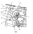
- FIG. 4 is a schematic representation in a partial axial section of the device of FIG. 1 , wherein the second crimping means are in a crimping position.
- the word “axial” is defined with respect to the direction of introduction of the cable into the crimping device, and the word radial is defined with respect to the planes perpendicular to said axial direction.
- the crimping device 1 of a contact (not shown) on the end portion of a cable (not shown) is described.
- the end portion of the cable to be crimped includes a stripped part showing the core of the cable.
- the contact extends about the end portion of the cable and more particularly about the stripped part and a part provided with the sheath.
- the crimping device 1 includes an axial bore 2 making it possible to introduce the end portion of the cable to be crimped.
- the bore 2 may go through the whole device or not.
- First crimping means 3 and second crimping means 4 extend about the bore 2 , in radial directions and are successively positioned in the axial direction.
- the first crimping means 3 make it possible to carry out the electric crimping, i.e. the crimping of the contact on the stripped part on the end portion of the cable.
- the second crimping means 4 make it possible to carry out a sealing crimping, i.e. the crimping of the contact on the part provided with the sheath of the end portion of the electric cable.
- the end portion of the cable is thus introduced on the second crimping means 4 side, so that the stripped part surrounded by the contact is positioned between the first crimping means 3 and that the part provided with the sheath is positioned between the second crimping means 4 .
- the first crimping means 3 include a plurality of punches 5 which are movable in translation in the radial direction between a distant position ( FIG. 1 ) making it possible to introduce the cable and the contact into the bore 2 and a crimping position ( FIG. 2 ) wherein the crimping means 3 are intended to apply pressure on the contact so as to carry out the crimping by crushing said contact against the stripped part of the end portion of the cable.
- Such translation motion is shown by the arrows F 1 in FIGS. 1 and 2 .
- the first crimping means 3 include four punches 5 positioned so as to form substantially an angle 90° between two successive punches 5 in the radial plane.
- the punches 5 include a crimping surface 8 positioned opposite the bore 2 . Such crimping surface 8 is so arranged as to apply the pressure on the contact prior to carrying out the crimping operation.
- the punches 5 are for example guided in translation between guides (not shown) positioned on either side of the end part of punches 5 , close to the bore 2 .
- the first crimping means 3 are associated with first moving means 6 , making it possible to move crimping means 3 between their distant position and their crimping position.
- the first moving means 6 are movable in translation in the axial direction as shown by the arrow F 2 in FIGS. 1 and 2 .
- the first moving means 6 include a ring 7 positioned partly about the punches 5 .
- these include an inclined surface 9 in the axial direction positioned opposite the crimping surface 8 in the radial direction.
- the ring 7 has an internal wall provided with inclined surfaces 10 forming a cam of the first moving means 3 .
- Such inclined surfaces 10 are each matching the inclined surface 9 of a punch 5 .
- the latter In order to provide the moving in axial translation of the ring 7 , the latter is operated with an endless screw (not shown), and means for transforming the rotation motion of the endless screw into a translation motion of the ring 7 are provided between said endless screw and said ring.
- the operation of the screw is controlled by electric actuating means, for example a motor (not shown).
- the latter may be associated with return means 14 such as springs, so arranged as to move the punches 5 in the radial direction upon the passage from the crimping position to the distant position.
- a movable stopper (not shown) may be positioned on the axial path of the first moving means 6 in order to limit the travel thereof. Then, the moving distance of the punches 5 may be adjusted upon the calibration of the device 1 for example and the crimping position can be defined according to the gauge of the end portion of the cable to be crimped. In addition, the position of the stopper may be adjusted in order to compensate for the wear of the punches by providing a longer travel than that initially provided if the punches are worn.
- the second crimping means 4 comprise a plurality of punches 15 which are movable in translation in a radial direction between a distant position ( FIGS. 1 and 2 ) making it possible to introduce the cable and the contact into the bore 2 , and a crimping position ( FIG. 4 ) wherein the crimping means 4 are intended to apply a pressure on the contact so as to carry out the crimping by crushing said contact against the part provided with a sheath of the end portion of the cable.
- Such translation motion is shown by the arrows F 3 in FIGS. 3 and 4 .
- the second crimping means 4 include eight punches 15 positioned so as to form substantially an angle of 45° between two successive punches 15 in the radial plane.
- the punches 15 include a crimping surface 16 positioned opposite the bore 2 .
- Such crimping surface 16 is so arranged as to apply a pressure on the contact in order to carry out the crimping.
- the crimping surface 16 is curved and the radius of curvature of such crimping surface 16 is greater than the radius of the biggest cable that the device will crimp. Then, the material of the contact is prevented from leaking through the punches 15 during the crimping operation and from forming protrusions about the contact.
- the punches 15 are mounted on a disc 18 radially punched to allow the passage of each punch 15 .
- the disc makes it possible to guide the translation motion of the punches 15 .
- the second crimping means 4 are associated with the second moving means 17 making it possible to move the crimping means 4 between their distant position and their crimping position.
- the second moving means 17 are movable in rotation about the axis of the bore 2 as shown by the arrow F 4 in FIGS. 3 and 4 .
- the second moving means 17 include a cam 21 in the form of a crown rotatingly mounted about the punches 15 .
- the punches 15 are each provided with a rounded cam surface 19 opposite the crimping surface 16 in the radial direction.
- Such rounded cam surfaces 19 are each received in a recess 20 of the cam 21 and positioned to rest against an internal wall of said recess.
- the internal wall is curved and has a decreasing diameter so as to progressively move the punches between their distant position and their crimping position upon the rotation of the cam from the distant position to the crimping position as can be seen in FIGS. 3 and 4 .
- the actuation in rotation of the cam 21 is controlled by electric actuating means, for example a motor (not shown).
- the motors controlling the rotation on the second moving means 17 and the translation of the first moving means 6 may be further controlled so that the operation of the motor controlling the actuation of the first moving means is started prior to that of the motor controlling the actuation of the second moving means.
- Other servo-controls of the motor may be considered, such as a simultaneous starting of the motors.
- the latter may be associated with return means (not shown) such as springs so arranged as to move the punches 15 in the radial direction upon the passage from the crimping position to the distant position.
- return means are for example mounted in the disc 18 .
- a movable stopper (not shown), may be positioned on the rotation path of the second moving means 17 in order to limit the travel thereof. Then, the moving distance of the punches 15 , and the crimping position may be defined according to the gauge of the end portion of the cable to be crimped may be adjusted upon the calibration of the device 1 for example. In addition, the position of the stopper may be adjusted in order to compensate for the wear of punches by providing a longer travel than that initially provided if the punches are worn.
- means may be provided for measuring the crimping efforts upon the crimping of the end portion of the cable.
- the measure may then be compared with a gauge showing the expected crimping effort for a certain cable gauge. If the efforts measured are more important than this gauge, it will be obvious that the adjustment of the device, more particularly the stoppers provided on the axial path and on the rotation path of the first and second moving means is not correct.
- the gauge may be associated with a step of validating the contact gauge, upon the adjustment of the device 1 . When the operator uses the device 1 , he/she adjusts the gauge, which indicates the gauge of the expected efforts corresponding to this gauge.
Landscapes
- Engineering & Computer Science (AREA)
- Manufacturing & Machinery (AREA)
- Manufacturing Of Electrical Connectors (AREA)
Abstract
Description
-
- first means for crimping the contact on the stripped part and second means for crimping the contact on the part provided with the sheath, said crimping means being positioned about the bore and being movable along a radial direction with respect to the bore between a distant position and upon the introduction of the cable and the contact into the bore and a crimping position wherein the crimping means are intended to apply a pressure on the contact so as to make the crimping;
- first and second means respectively, for moving said first and second crimping means between their distant position and their crimping position, said first and second moving means being each provided with at least one cam cooperating with the crimping means so as to move them in the radial direction;
- means for actuating said moving means;
the first moving means being actuated in translation in an axial direction and the second moving means being rotatingly actuated about the axis of the bore so as to move the first and second crimping means in the radial direction between their distant position and their crimping position.
Claims (14)
Applications Claiming Priority (4)
| Application Number | Priority Date | Filing Date | Title |
|---|---|---|---|
| FR60/2496 | 2006-03-22 | ||
| FR6002496 | 2006-03-22 | ||
| FR0602496A FR2899032B1 (en) | 2006-03-22 | 2006-03-22 | CRIMPING DEVICE FOR PERFORMING ELECTRICAL CRIMPING AND SEALING CRIMPING |
| PCT/FR2007/000485 WO2007107653A1 (en) | 2006-03-22 | 2007-03-22 | Crimping device for electrical crimping and sealed crimping |
Publications (2)
| Publication Number | Publication Date |
|---|---|
| US20090119909A1 US20090119909A1 (en) | 2009-05-14 |
| US8024855B2 true US8024855B2 (en) | 2011-09-27 |
Family
ID=37192553
Family Applications (1)
| Application Number | Title | Priority Date | Filing Date |
|---|---|---|---|
| US12/293,940 Expired - Fee Related US8024855B2 (en) | 2006-03-22 | 2007-03-22 | Crimping device for electrical crimping and sealed crimping |
Country Status (4)
| Country | Link |
|---|---|
| US (1) | US8024855B2 (en) |
| EP (1) | EP1994611A1 (en) |
| FR (1) | FR2899032B1 (en) |
| WO (1) | WO2007107653A1 (en) |
Cited By (1)
| Publication number | Priority date | Publication date | Assignee | Title |
|---|---|---|---|---|
| DE102023106464A1 (en) | 2023-03-15 | 2024-09-19 | Md Elektronik Gmbh | Crimping unit for a crimping tool |
Families Citing this family (4)
| Publication number | Priority date | Publication date | Assignee | Title |
|---|---|---|---|---|
| US11193249B2 (en) * | 2019-05-28 | 2021-12-07 | Ari J. Ostrow | Robotic de-icer |
| CN111243907B (en) * | 2019-12-26 | 2021-12-17 | 河南平高电气股份有限公司 | Crimping device for assembling movable end assembly of circuit breaker |
| CN112382911A (en) * | 2020-11-04 | 2021-02-19 | 青岛铭青机电有限公司 | General type wire rod terminal riveting mechanism |
| CN112620548B (en) * | 2020-12-10 | 2025-10-03 | 昆山名威精密工业有限公司 | A crimping tool for fine stainless steel guide wire and sleeve and a crimping method thereof |
Citations (9)
| Publication number | Priority date | Publication date | Assignee | Title |
|---|---|---|---|---|
| US2985047A (en) | 1959-03-13 | 1961-05-23 | Cannon Electric Co | Tool with cam-actuated jaw closing means |
| GB1195193A (en) | 1966-06-02 | 1970-06-17 | Hydraul Fittings Ltd | Crimping and Swaging Machines. |
| US4244091A (en) | 1979-09-21 | 1981-01-13 | The Gates Rubber Company | Hose crimping apparatus |
| DE3203681A1 (en) | 1982-02-04 | 1983-08-11 | Grote & Hartmann Gmbh & Co Kg, 5600 Wuppertal | Height-adjusting device for the upper prop of a securing tool |
| US5038461A (en) * | 1989-08-31 | 1991-08-13 | Societe Nationale Industrielle Et Aerospatiale | Device and system for crimping connecting elements on electric conductors |
| US5092152A (en) | 1990-09-28 | 1992-03-03 | Parker-Hannifin Corporation | Crimping machine |
| US20060019550A1 (en) | 2004-07-22 | 2006-01-26 | Krzysztof Krajewski | Hardened metal implant for indenter of a crimp tool for crimping pin and socket contacts |
| WO2006012979A1 (en) | 2004-07-26 | 2006-02-09 | Airbus France | Tool and method for crimping a contact onto a cable |
| US7448243B1 (en) * | 2005-04-15 | 2008-11-11 | Machine Solutions, Inc. | Swaging technology |
-
2006
- 2006-03-22 FR FR0602496A patent/FR2899032B1/en not_active Expired - Fee Related
-
2007
- 2007-03-22 WO PCT/FR2007/000485 patent/WO2007107653A1/en not_active Ceased
- 2007-03-22 US US12/293,940 patent/US8024855B2/en not_active Expired - Fee Related
- 2007-03-22 EP EP07731174A patent/EP1994611A1/en not_active Withdrawn
Patent Citations (9)
| Publication number | Priority date | Publication date | Assignee | Title |
|---|---|---|---|---|
| US2985047A (en) | 1959-03-13 | 1961-05-23 | Cannon Electric Co | Tool with cam-actuated jaw closing means |
| GB1195193A (en) | 1966-06-02 | 1970-06-17 | Hydraul Fittings Ltd | Crimping and Swaging Machines. |
| US4244091A (en) | 1979-09-21 | 1981-01-13 | The Gates Rubber Company | Hose crimping apparatus |
| DE3203681A1 (en) | 1982-02-04 | 1983-08-11 | Grote & Hartmann Gmbh & Co Kg, 5600 Wuppertal | Height-adjusting device for the upper prop of a securing tool |
| US5038461A (en) * | 1989-08-31 | 1991-08-13 | Societe Nationale Industrielle Et Aerospatiale | Device and system for crimping connecting elements on electric conductors |
| US5092152A (en) | 1990-09-28 | 1992-03-03 | Parker-Hannifin Corporation | Crimping machine |
| US20060019550A1 (en) | 2004-07-22 | 2006-01-26 | Krzysztof Krajewski | Hardened metal implant for indenter of a crimp tool for crimping pin and socket contacts |
| WO2006012979A1 (en) | 2004-07-26 | 2006-02-09 | Airbus France | Tool and method for crimping a contact onto a cable |
| US7448243B1 (en) * | 2005-04-15 | 2008-11-11 | Machine Solutions, Inc. | Swaging technology |
Cited By (1)
| Publication number | Priority date | Publication date | Assignee | Title |
|---|---|---|---|---|
| DE102023106464A1 (en) | 2023-03-15 | 2024-09-19 | Md Elektronik Gmbh | Crimping unit for a crimping tool |
Also Published As
| Publication number | Publication date |
|---|---|
| US20090119909A1 (en) | 2009-05-14 |
| EP1994611A1 (en) | 2008-11-26 |
| FR2899032A1 (en) | 2007-09-28 |
| WO2007107653A1 (en) | 2007-09-27 |
| FR2899032B1 (en) | 2008-07-04 |
Similar Documents
| Publication | Publication Date | Title |
|---|---|---|
| US8024855B2 (en) | Crimping device for electrical crimping and sealed crimping | |
| JP6224650B2 (en) | Crimping tool and crimping die | |
| US11601034B2 (en) | Method and device for deforming U-shaped electric conductors | |
| US8801300B2 (en) | Fiber optic cable end fixture and fiber optic cable end fixing method | |
| US20150236464A1 (en) | Smart conductor/connector selecting die | |
| US20210226355A1 (en) | Arrangement, Tool and Method For Producing Such An Arrangement | |
| CN107959264B (en) | Stripping tool and method for stripping | |
| KR20030087622A (en) | Pressing tool | |
| JP2007223028A (en) | Crimping die and crimping tool | |
| WO2017141866A1 (en) | Terminal crimping device, terminal crimping tool, and method for producing terminal-crimped electric wire | |
| US7418851B2 (en) | Device for crimping a contact on a cable | |
| US9231340B2 (en) | Releaseable electrical contact connection | |
| US7748108B2 (en) | Tool for crimping a contact onto a cable | |
| EP3776756B1 (en) | Decagon compression die | |
| JP2010029040A (en) | Indirect hot-line work tool and indirect hot-line connection method | |
| US11381067B2 (en) | Method for producing an explosion-proof line bushing, and explosion-proof line bushing | |
| JP5889228B2 (en) | Electric wire manufacturing method with terminal and core wire exposure device | |
| CN102165652B (en) | Terminal crimping device | |
| US20230101509A1 (en) | Terminal crimping apparatus and terminal crimping method | |
| KR101477617B1 (en) | Water preventing connector cover | |
| US7223116B2 (en) | Insulation piercing connecting device | |
| US6203023B1 (en) | Cable inlet | |
| AU2021327144A1 (en) | Hand pliers designed to carry out crimping, and hand pliers comprising a plier head | |
| JP6895351B2 (en) | Terminal crimping device | |
| US20180183198A1 (en) | Crimp Indentor, Crimping Tool and Method of Producing a Crimp Indentor |
Legal Events
| Date | Code | Title | Description |
|---|---|---|---|
| AS | Assignment |
Owner name: ROBOTIQUES 3 DIMENSIONS SARL, FRANCE Free format text: ASSIGNMENT OF ASSIGNORS INTEREST;ASSIGNORS:GRY-GOROWICZ, SERGE;GAUTHIER, PATRICK;COSTE, FLAVIEN;REEL/FRAME:021927/0236;SIGNING DATES FROM 20081110 TO 20081116 Owner name: ROBOTIQUES 3 DIMENSIONS SARL, FRANCE Free format text: ASSIGNMENT OF ASSIGNORS INTEREST;ASSIGNORS:GRY-GOROWICZ, SERGE;GAUTHIER, PATRICK;COSTE, FLAVIEN;SIGNING DATES FROM 20081110 TO 20081116;REEL/FRAME:021927/0236 |
|
| AS | Assignment |
Owner name: LABINAL SA, FRANCE Free format text: ASSIGNMENT OF ASSIGNORS INTEREST;ASSIGNOR:ROBOTIQUES 3 DIMENSIONS;REEL/FRAME:026779/0350 Effective date: 20070719 |
|
| STCF | Information on status: patent grant |
Free format text: PATENTED CASE |
|
| CC | Certificate of correction | ||
| FPAY | Fee payment |
Year of fee payment: 4 |
|
| FEPP | Fee payment procedure |
Free format text: MAINTENANCE FEE REMINDER MAILED (ORIGINAL EVENT CODE: REM.); ENTITY STATUS OF PATENT OWNER: LARGE ENTITY |
|
| LAPS | Lapse for failure to pay maintenance fees |
Free format text: PATENT EXPIRED FOR FAILURE TO PAY MAINTENANCE FEES (ORIGINAL EVENT CODE: EXP.); ENTITY STATUS OF PATENT OWNER: LARGE ENTITY |
|
| STCH | Information on status: patent discontinuation |
Free format text: PATENT EXPIRED DUE TO NONPAYMENT OF MAINTENANCE FEES UNDER 37 CFR 1.362 |
|
| FP | Lapsed due to failure to pay maintenance fee |
Effective date: 20190927 |