US8007401B2 - Hybrid vehicle drive control apparatus and method - Google Patents
Hybrid vehicle drive control apparatus and method Download PDFInfo
- Publication number
- US8007401B2 US8007401B2 US12/061,963 US6196308A US8007401B2 US 8007401 B2 US8007401 B2 US 8007401B2 US 6196308 A US6196308 A US 6196308A US 8007401 B2 US8007401 B2 US 8007401B2
- Authority
- US
- United States
- Prior art keywords
- torque
- generator
- motor
- engine
- engine torque
- Prior art date
- Legal status (The legal status is an assumption and is not a legal conclusion. Google has not performed a legal analysis and makes no representation as to the accuracy of the status listed.)
- Active, expires
Links
Images




Classifications
-
- B—PERFORMING OPERATIONS; TRANSPORTING
- B60—VEHICLES IN GENERAL
- B60K—ARRANGEMENT OR MOUNTING OF PROPULSION UNITS OR OF TRANSMISSIONS IN VEHICLES; ARRANGEMENT OR MOUNTING OF PLURAL DIVERSE PRIME-MOVERS IN VEHICLES; AUXILIARY DRIVES FOR VEHICLES; INSTRUMENTATION OR DASHBOARDS FOR VEHICLES; ARRANGEMENTS IN CONNECTION WITH COOLING, AIR INTAKE, GAS EXHAUST OR FUEL SUPPLY OF PROPULSION UNITS IN VEHICLES
- B60K6/00—Arrangement or mounting of plural diverse prime-movers for mutual or common propulsion, e.g. hybrid propulsion systems comprising electric motors and internal combustion engines
- B60K6/20—Arrangement or mounting of plural diverse prime-movers for mutual or common propulsion, e.g. hybrid propulsion systems comprising electric motors and internal combustion engines the prime-movers consisting of electric motors and internal combustion engines, e.g. HEVs
- B60K6/22—Arrangement or mounting of plural diverse prime-movers for mutual or common propulsion, e.g. hybrid propulsion systems comprising electric motors and internal combustion engines the prime-movers consisting of electric motors and internal combustion engines, e.g. HEVs characterised by apparatus, components or means specially adapted for HEVs
- B60K6/36—Arrangement or mounting of plural diverse prime-movers for mutual or common propulsion, e.g. hybrid propulsion systems comprising electric motors and internal combustion engines the prime-movers consisting of electric motors and internal combustion engines, e.g. HEVs characterised by apparatus, components or means specially adapted for HEVs characterised by the transmission gearings
- B60K6/365—Arrangement or mounting of plural diverse prime-movers for mutual or common propulsion, e.g. hybrid propulsion systems comprising electric motors and internal combustion engines the prime-movers consisting of electric motors and internal combustion engines, e.g. HEVs characterised by apparatus, components or means specially adapted for HEVs characterised by the transmission gearings with the gears having orbital motion
-
- B—PERFORMING OPERATIONS; TRANSPORTING
- B60—VEHICLES IN GENERAL
- B60W—CONJOINT CONTROL OF VEHICLE SUB-UNITS OF DIFFERENT TYPE OR DIFFERENT FUNCTION; CONTROL SYSTEMS SPECIALLY ADAPTED FOR HYBRID VEHICLES; ROAD VEHICLE DRIVE CONTROL SYSTEMS FOR PURPOSES NOT RELATED TO THE CONTROL OF A PARTICULAR SUB-UNIT
- B60W20/00—Control systems specially adapted for hybrid vehicles
- B60W20/10—Controlling the power contribution of each of the prime movers to meet required power demand
-
- B—PERFORMING OPERATIONS; TRANSPORTING
- B60—VEHICLES IN GENERAL
- B60K—ARRANGEMENT OR MOUNTING OF PROPULSION UNITS OR OF TRANSMISSIONS IN VEHICLES; ARRANGEMENT OR MOUNTING OF PLURAL DIVERSE PRIME-MOVERS IN VEHICLES; AUXILIARY DRIVES FOR VEHICLES; INSTRUMENTATION OR DASHBOARDS FOR VEHICLES; ARRANGEMENTS IN CONNECTION WITH COOLING, AIR INTAKE, GAS EXHAUST OR FUEL SUPPLY OF PROPULSION UNITS IN VEHICLES
- B60K6/00—Arrangement or mounting of plural diverse prime-movers for mutual or common propulsion, e.g. hybrid propulsion systems comprising electric motors and internal combustion engines
- B60K6/20—Arrangement or mounting of plural diverse prime-movers for mutual or common propulsion, e.g. hybrid propulsion systems comprising electric motors and internal combustion engines the prime-movers consisting of electric motors and internal combustion engines, e.g. HEVs
- B60K6/42—Arrangement or mounting of plural diverse prime-movers for mutual or common propulsion, e.g. hybrid propulsion systems comprising electric motors and internal combustion engines the prime-movers consisting of electric motors and internal combustion engines, e.g. HEVs characterised by the architecture of the hybrid electric vehicle
- B60K6/48—Parallel type
-
- B—PERFORMING OPERATIONS; TRANSPORTING
- B60—VEHICLES IN GENERAL
- B60K—ARRANGEMENT OR MOUNTING OF PROPULSION UNITS OR OF TRANSMISSIONS IN VEHICLES; ARRANGEMENT OR MOUNTING OF PLURAL DIVERSE PRIME-MOVERS IN VEHICLES; AUXILIARY DRIVES FOR VEHICLES; INSTRUMENTATION OR DASHBOARDS FOR VEHICLES; ARRANGEMENTS IN CONNECTION WITH COOLING, AIR INTAKE, GAS EXHAUST OR FUEL SUPPLY OF PROPULSION UNITS IN VEHICLES
- B60K6/00—Arrangement or mounting of plural diverse prime-movers for mutual or common propulsion, e.g. hybrid propulsion systems comprising electric motors and internal combustion engines
- B60K6/20—Arrangement or mounting of plural diverse prime-movers for mutual or common propulsion, e.g. hybrid propulsion systems comprising electric motors and internal combustion engines the prime-movers consisting of electric motors and internal combustion engines, e.g. HEVs
- B60K6/50—Architecture of the driveline characterised by arrangement or kind of transmission units
- B60K6/54—Transmission for changing ratio
- B60K6/547—Transmission for changing ratio the transmission being a stepped gearing
-
- B—PERFORMING OPERATIONS; TRANSPORTING
- B60—VEHICLES IN GENERAL
- B60W—CONJOINT CONTROL OF VEHICLE SUB-UNITS OF DIFFERENT TYPE OR DIFFERENT FUNCTION; CONTROL SYSTEMS SPECIALLY ADAPTED FOR HYBRID VEHICLES; ROAD VEHICLE DRIVE CONTROL SYSTEMS FOR PURPOSES NOT RELATED TO THE CONTROL OF A PARTICULAR SUB-UNIT
- B60W10/00—Conjoint control of vehicle sub-units of different type or different function
- B60W10/02—Conjoint control of vehicle sub-units of different type or different function including control of driveline clutches
-
- B—PERFORMING OPERATIONS; TRANSPORTING
- B60—VEHICLES IN GENERAL
- B60W—CONJOINT CONTROL OF VEHICLE SUB-UNITS OF DIFFERENT TYPE OR DIFFERENT FUNCTION; CONTROL SYSTEMS SPECIALLY ADAPTED FOR HYBRID VEHICLES; ROAD VEHICLE DRIVE CONTROL SYSTEMS FOR PURPOSES NOT RELATED TO THE CONTROL OF A PARTICULAR SUB-UNIT
- B60W10/00—Conjoint control of vehicle sub-units of different type or different function
- B60W10/04—Conjoint control of vehicle sub-units of different type or different function including control of propulsion units
- B60W10/06—Conjoint control of vehicle sub-units of different type or different function including control of propulsion units including control of combustion engines
-
- B—PERFORMING OPERATIONS; TRANSPORTING
- B60—VEHICLES IN GENERAL
- B60W—CONJOINT CONTROL OF VEHICLE SUB-UNITS OF DIFFERENT TYPE OR DIFFERENT FUNCTION; CONTROL SYSTEMS SPECIALLY ADAPTED FOR HYBRID VEHICLES; ROAD VEHICLE DRIVE CONTROL SYSTEMS FOR PURPOSES NOT RELATED TO THE CONTROL OF A PARTICULAR SUB-UNIT
- B60W10/00—Conjoint control of vehicle sub-units of different type or different function
- B60W10/04—Conjoint control of vehicle sub-units of different type or different function including control of propulsion units
- B60W10/08—Conjoint control of vehicle sub-units of different type or different function including control of propulsion units including control of electric propulsion units, e.g. motors or generators
-
- B—PERFORMING OPERATIONS; TRANSPORTING
- B60—VEHICLES IN GENERAL
- B60W—CONJOINT CONTROL OF VEHICLE SUB-UNITS OF DIFFERENT TYPE OR DIFFERENT FUNCTION; CONTROL SYSTEMS SPECIALLY ADAPTED FOR HYBRID VEHICLES; ROAD VEHICLE DRIVE CONTROL SYSTEMS FOR PURPOSES NOT RELATED TO THE CONTROL OF A PARTICULAR SUB-UNIT
- B60W20/00—Control systems specially adapted for hybrid vehicles
-
- B—PERFORMING OPERATIONS; TRANSPORTING
- B60—VEHICLES IN GENERAL
- B60W—CONJOINT CONTROL OF VEHICLE SUB-UNITS OF DIFFERENT TYPE OR DIFFERENT FUNCTION; CONTROL SYSTEMS SPECIALLY ADAPTED FOR HYBRID VEHICLES; ROAD VEHICLE DRIVE CONTROL SYSTEMS FOR PURPOSES NOT RELATED TO THE CONTROL OF A PARTICULAR SUB-UNIT
- B60W50/00—Details of control systems for road vehicle drive control not related to the control of a particular sub-unit, e.g. process diagnostic or vehicle driver interfaces
- B60W50/08—Interaction between the driver and the control system
-
- B—PERFORMING OPERATIONS; TRANSPORTING
- B60—VEHICLES IN GENERAL
- B60K—ARRANGEMENT OR MOUNTING OF PROPULSION UNITS OR OF TRANSMISSIONS IN VEHICLES; ARRANGEMENT OR MOUNTING OF PLURAL DIVERSE PRIME-MOVERS IN VEHICLES; AUXILIARY DRIVES FOR VEHICLES; INSTRUMENTATION OR DASHBOARDS FOR VEHICLES; ARRANGEMENTS IN CONNECTION WITH COOLING, AIR INTAKE, GAS EXHAUST OR FUEL SUPPLY OF PROPULSION UNITS IN VEHICLES
- B60K6/00—Arrangement or mounting of plural diverse prime-movers for mutual or common propulsion, e.g. hybrid propulsion systems comprising electric motors and internal combustion engines
- B60K6/20—Arrangement or mounting of plural diverse prime-movers for mutual or common propulsion, e.g. hybrid propulsion systems comprising electric motors and internal combustion engines the prime-movers consisting of electric motors and internal combustion engines, e.g. HEVs
- B60K6/22—Arrangement or mounting of plural diverse prime-movers for mutual or common propulsion, e.g. hybrid propulsion systems comprising electric motors and internal combustion engines the prime-movers consisting of electric motors and internal combustion engines, e.g. HEVs characterised by apparatus, components or means specially adapted for HEVs
- B60K6/26—Arrangement or mounting of plural diverse prime-movers for mutual or common propulsion, e.g. hybrid propulsion systems comprising electric motors and internal combustion engines the prime-movers consisting of electric motors and internal combustion engines, e.g. HEVs characterised by apparatus, components or means specially adapted for HEVs characterised by the motors or the generators
- B60K2006/268—Electric drive motor starts the engine, i.e. used as starter motor
-
- B—PERFORMING OPERATIONS; TRANSPORTING
- B60—VEHICLES IN GENERAL
- B60L—PROPULSION OF ELECTRICALLY-PROPELLED VEHICLES; SUPPLYING ELECTRIC POWER FOR AUXILIARY EQUIPMENT OF ELECTRICALLY-PROPELLED VEHICLES; ELECTRODYNAMIC BRAKE SYSTEMS FOR VEHICLES IN GENERAL; MAGNETIC SUSPENSION OR LEVITATION FOR VEHICLES; MONITORING OPERATING VARIABLES OF ELECTRICALLY-PROPELLED VEHICLES; ELECTRIC SAFETY DEVICES FOR ELECTRICALLY-PROPELLED VEHICLES
- B60L2240/00—Control parameters of input or output; Target parameters
- B60L2240/40—Drive Train control parameters
- B60L2240/42—Drive Train control parameters related to electric machines
- B60L2240/421—Speed
-
- B—PERFORMING OPERATIONS; TRANSPORTING
- B60—VEHICLES IN GENERAL
- B60L—PROPULSION OF ELECTRICALLY-PROPELLED VEHICLES; SUPPLYING ELECTRIC POWER FOR AUXILIARY EQUIPMENT OF ELECTRICALLY-PROPELLED VEHICLES; ELECTRODYNAMIC BRAKE SYSTEMS FOR VEHICLES IN GENERAL; MAGNETIC SUSPENSION OR LEVITATION FOR VEHICLES; MONITORING OPERATING VARIABLES OF ELECTRICALLY-PROPELLED VEHICLES; ELECTRIC SAFETY DEVICES FOR ELECTRICALLY-PROPELLED VEHICLES
- B60L2240/00—Control parameters of input or output; Target parameters
- B60L2240/40—Drive Train control parameters
- B60L2240/44—Drive Train control parameters related to combustion engines
- B60L2240/441—Speed
-
- B—PERFORMING OPERATIONS; TRANSPORTING
- B60—VEHICLES IN GENERAL
- B60W—CONJOINT CONTROL OF VEHICLE SUB-UNITS OF DIFFERENT TYPE OR DIFFERENT FUNCTION; CONTROL SYSTEMS SPECIALLY ADAPTED FOR HYBRID VEHICLES; ROAD VEHICLE DRIVE CONTROL SYSTEMS FOR PURPOSES NOT RELATED TO THE CONTROL OF A PARTICULAR SUB-UNIT
- B60W2510/00—Input parameters relating to a particular sub-units
- B60W2510/06—Combustion engines, Gas turbines
- B60W2510/0638—Engine speed
-
- B—PERFORMING OPERATIONS; TRANSPORTING
- B60—VEHICLES IN GENERAL
- B60W—CONJOINT CONTROL OF VEHICLE SUB-UNITS OF DIFFERENT TYPE OR DIFFERENT FUNCTION; CONTROL SYSTEMS SPECIALLY ADAPTED FOR HYBRID VEHICLES; ROAD VEHICLE DRIVE CONTROL SYSTEMS FOR PURPOSES NOT RELATED TO THE CONTROL OF A PARTICULAR SUB-UNIT
- B60W2510/00—Input parameters relating to a particular sub-units
- B60W2510/06—Combustion engines, Gas turbines
- B60W2510/0657—Engine torque
-
- B—PERFORMING OPERATIONS; TRANSPORTING
- B60—VEHICLES IN GENERAL
- B60W—CONJOINT CONTROL OF VEHICLE SUB-UNITS OF DIFFERENT TYPE OR DIFFERENT FUNCTION; CONTROL SYSTEMS SPECIALLY ADAPTED FOR HYBRID VEHICLES; ROAD VEHICLE DRIVE CONTROL SYSTEMS FOR PURPOSES NOT RELATED TO THE CONTROL OF A PARTICULAR SUB-UNIT
- B60W2510/00—Input parameters relating to a particular sub-units
- B60W2510/08—Electric propulsion units
- B60W2510/081—Speed
-
- B—PERFORMING OPERATIONS; TRANSPORTING
- B60—VEHICLES IN GENERAL
- B60W—CONJOINT CONTROL OF VEHICLE SUB-UNITS OF DIFFERENT TYPE OR DIFFERENT FUNCTION; CONTROL SYSTEMS SPECIALLY ADAPTED FOR HYBRID VEHICLES; ROAD VEHICLE DRIVE CONTROL SYSTEMS FOR PURPOSES NOT RELATED TO THE CONTROL OF A PARTICULAR SUB-UNIT
- B60W2510/00—Input parameters relating to a particular sub-units
- B60W2510/08—Electric propulsion units
- B60W2510/083—Torque
-
- B—PERFORMING OPERATIONS; TRANSPORTING
- B60—VEHICLES IN GENERAL
- B60W—CONJOINT CONTROL OF VEHICLE SUB-UNITS OF DIFFERENT TYPE OR DIFFERENT FUNCTION; CONTROL SYSTEMS SPECIALLY ADAPTED FOR HYBRID VEHICLES; ROAD VEHICLE DRIVE CONTROL SYSTEMS FOR PURPOSES NOT RELATED TO THE CONTROL OF A PARTICULAR SUB-UNIT
- B60W2510/00—Input parameters relating to a particular sub-units
- B60W2510/24—Energy storage means
- B60W2510/242—Energy storage means for electrical energy
- B60W2510/244—Charge state
-
- B—PERFORMING OPERATIONS; TRANSPORTING
- B60—VEHICLES IN GENERAL
- B60W—CONJOINT CONTROL OF VEHICLE SUB-UNITS OF DIFFERENT TYPE OR DIFFERENT FUNCTION; CONTROL SYSTEMS SPECIALLY ADAPTED FOR HYBRID VEHICLES; ROAD VEHICLE DRIVE CONTROL SYSTEMS FOR PURPOSES NOT RELATED TO THE CONTROL OF A PARTICULAR SUB-UNIT
- B60W2540/00—Input parameters relating to occupants
- B60W2540/10—Accelerator pedal position
-
- B—PERFORMING OPERATIONS; TRANSPORTING
- B60—VEHICLES IN GENERAL
- B60W—CONJOINT CONTROL OF VEHICLE SUB-UNITS OF DIFFERENT TYPE OR DIFFERENT FUNCTION; CONTROL SYSTEMS SPECIALLY ADAPTED FOR HYBRID VEHICLES; ROAD VEHICLE DRIVE CONTROL SYSTEMS FOR PURPOSES NOT RELATED TO THE CONTROL OF A PARTICULAR SUB-UNIT
- B60W2710/00—Output or target parameters relating to a particular sub-units
- B60W2710/02—Clutches
- B60W2710/027—Clutch torque
-
- B—PERFORMING OPERATIONS; TRANSPORTING
- B60—VEHICLES IN GENERAL
- B60W—CONJOINT CONTROL OF VEHICLE SUB-UNITS OF DIFFERENT TYPE OR DIFFERENT FUNCTION; CONTROL SYSTEMS SPECIALLY ADAPTED FOR HYBRID VEHICLES; ROAD VEHICLE DRIVE CONTROL SYSTEMS FOR PURPOSES NOT RELATED TO THE CONTROL OF A PARTICULAR SUB-UNIT
- B60W2710/00—Output or target parameters relating to a particular sub-units
- B60W2710/10—Change speed gearings
- B60W2710/105—Output torque
-
- B—PERFORMING OPERATIONS; TRANSPORTING
- B60—VEHICLES IN GENERAL
- B60W—CONJOINT CONTROL OF VEHICLE SUB-UNITS OF DIFFERENT TYPE OR DIFFERENT FUNCTION; CONTROL SYSTEMS SPECIALLY ADAPTED FOR HYBRID VEHICLES; ROAD VEHICLE DRIVE CONTROL SYSTEMS FOR PURPOSES NOT RELATED TO THE CONTROL OF A PARTICULAR SUB-UNIT
- B60W50/00—Details of control systems for road vehicle drive control not related to the control of a particular sub-unit, e.g. process diagnostic or vehicle driver interfaces
- B60W50/08—Interaction between the driver and the control system
- B60W50/10—Interpretation of driver requests or demands
-
- Y—GENERAL TAGGING OF NEW TECHNOLOGICAL DEVELOPMENTS; GENERAL TAGGING OF CROSS-SECTIONAL TECHNOLOGIES SPANNING OVER SEVERAL SECTIONS OF THE IPC; TECHNICAL SUBJECTS COVERED BY FORMER USPC CROSS-REFERENCE ART COLLECTIONS [XRACs] AND DIGESTS
- Y02—TECHNOLOGIES OR APPLICATIONS FOR MITIGATION OR ADAPTATION AGAINST CLIMATE CHANGE
- Y02T—CLIMATE CHANGE MITIGATION TECHNOLOGIES RELATED TO TRANSPORTATION
- Y02T10/00—Road transport of goods or passengers
- Y02T10/10—Internal combustion engine [ICE] based vehicles
- Y02T10/40—Engine management systems
-
- Y—GENERAL TAGGING OF NEW TECHNOLOGICAL DEVELOPMENTS; GENERAL TAGGING OF CROSS-SECTIONAL TECHNOLOGIES SPANNING OVER SEVERAL SECTIONS OF THE IPC; TECHNICAL SUBJECTS COVERED BY FORMER USPC CROSS-REFERENCE ART COLLECTIONS [XRACs] AND DIGESTS
- Y02—TECHNOLOGIES OR APPLICATIONS FOR MITIGATION OR ADAPTATION AGAINST CLIMATE CHANGE
- Y02T—CLIMATE CHANGE MITIGATION TECHNOLOGIES RELATED TO TRANSPORTATION
- Y02T10/00—Road transport of goods or passengers
- Y02T10/60—Other road transportation technologies with climate change mitigation effect
-
- Y—GENERAL TAGGING OF NEW TECHNOLOGICAL DEVELOPMENTS; GENERAL TAGGING OF CROSS-SECTIONAL TECHNOLOGIES SPANNING OVER SEVERAL SECTIONS OF THE IPC; TECHNICAL SUBJECTS COVERED BY FORMER USPC CROSS-REFERENCE ART COLLECTIONS [XRACs] AND DIGESTS
- Y02—TECHNOLOGIES OR APPLICATIONS FOR MITIGATION OR ADAPTATION AGAINST CLIMATE CHANGE
- Y02T—CLIMATE CHANGE MITIGATION TECHNOLOGIES RELATED TO TRANSPORTATION
- Y02T10/00—Road transport of goods or passengers
- Y02T10/60—Other road transportation technologies with climate change mitigation effect
- Y02T10/62—Hybrid vehicles
-
- Y—GENERAL TAGGING OF NEW TECHNOLOGICAL DEVELOPMENTS; GENERAL TAGGING OF CROSS-SECTIONAL TECHNOLOGIES SPANNING OVER SEVERAL SECTIONS OF THE IPC; TECHNICAL SUBJECTS COVERED BY FORMER USPC CROSS-REFERENCE ART COLLECTIONS [XRACs] AND DIGESTS
- Y02—TECHNOLOGIES OR APPLICATIONS FOR MITIGATION OR ADAPTATION AGAINST CLIMATE CHANGE
- Y02T—CLIMATE CHANGE MITIGATION TECHNOLOGIES RELATED TO TRANSPORTATION
- Y02T10/00—Road transport of goods or passengers
- Y02T10/60—Other road transportation technologies with climate change mitigation effect
- Y02T10/64—Electric machine technologies in electromobility
-
- Y—GENERAL TAGGING OF NEW TECHNOLOGICAL DEVELOPMENTS; GENERAL TAGGING OF CROSS-SECTIONAL TECHNOLOGIES SPANNING OVER SEVERAL SECTIONS OF THE IPC; TECHNICAL SUBJECTS COVERED BY FORMER USPC CROSS-REFERENCE ART COLLECTIONS [XRACs] AND DIGESTS
- Y02—TECHNOLOGIES OR APPLICATIONS FOR MITIGATION OR ADAPTATION AGAINST CLIMATE CHANGE
- Y02T—CLIMATE CHANGE MITIGATION TECHNOLOGIES RELATED TO TRANSPORTATION
- Y02T10/00—Road transport of goods or passengers
- Y02T10/80—Technologies aiming to reduce greenhouse gasses emissions common to all road transportation technologies
- Y02T10/84—Data processing systems or methods, management, administration
Definitions
- the invention relates generally to a hybrid vehicle drive control apparatus and method that improves the response of a drive power to an accelerator pedal operation by a driver.
- Unexamined Japanese Patent Publication No. 2006-301195 discloses one type of a hybrid drive apparatus for hybrid vehicles.
- a target drive torque for a vehicle wheel drive system, a target motor-generator torque and a target engine torque are calculated based on an accelerator pedal depression amount, vehicle speed, state of charge of a battery and engine speed.
- a target drive torque is calculated based on an accelerator pedal depression amount and a vehicle speed. Then, an engine torque that optimizes the fuel consumption efficiency of the engine is retrieved based on an engine rotation speed by reference to a fuel consumption efficiency optimizing control map. A retrieved fuel consumption efficiency optimizing engine torque is determined as a target engine torque. Then, a target motor-generator torque is determined so that the sum of the target engine torque and the target motor-generator torque is equal to the target drive torque.
- Embodiments of a hybrid vehicle drive control apparatus for a vehicle including an engine and a motor-generator are taught herein.
- One such apparatus includes a controller.
- the controller for example, is configured to control a motor-generator torque of the motor-generator to obtain a target drive torque wherein the target drive torque is equal to the sum of an engine torque of the engine and the motor-generator torque.
- the controller is also configured to determine whether a drive mode requested by a driver is a power mode that attaches greater importance to an acceleration performance than to a fuel consumption efficiency and to use a power mode engine torque that is larger than an optimum fuel consumption efficiency engine torque as a target engine torque of the engine when the drive mode requested by the driver is the power mode.
- An example of one method includes controlling a motor-generator torque of the motor-generator to obtain a target drive torque wherein the target drive torque is equal to the sum of an engine torque of the engine and the motor-generator torque and using a power mode engine torque that is larger than an optimum fuel consumption efficiency engine torque as a target engine torque of the engine when acceleration performance is preferred over fuel consumption efficiency.
- FIG. 1 is a schematic plan view of a powertrain for a hybrid vehicle to which a control apparatus according to a first embodiment of the invention can be applied;
- FIG. 2 is a schematic plan view of another powertrain for a hybrid vehicle to which the control apparatus according to the first embodiment of the invention can be applied;
- FIG. 3 is a schematic plan view of a still other powertrain for a hybrid vehicle to which the control apparatus according to the first embodiment of the invention can be applied;
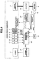
- FIG. 4 is a block diagram of a control system for the powertrains shown in FIGS. 1 to 3 ;
- FIG. 5 is a flowchart showing a control of a target engine torque calculated by an integrated controller of FIG. 4 ;
- FIG. 6 is a graph showing an engine torque and a generator torque determined by the control of FIG. 5 ;
- FIG. 7 is a graph view showing a target engine torque and an assist torque that is determined by the control described in FIG. 5 ;
- FIG. 8 is a time chart showing a variation of a vehicle drive torque by the control described in FIG. 5 ;
- FIG. 9 is a flowchart of another control of a target engine torque that is calculated by the integrated controller of FIG. 4 according to a second embodiment of the invention.
- FIG. 10 is a graph view showing an engine torque and a generator torque that is determined by the control described in FIG. 9 ;
- FIG. 11 is a time chart showing a variation of a vehicle drive torque by the control described in FIG. 9 ;
- FIG. 12 is a chargeable/dischargeable electric power graph for a power mode
- FIG. 13 is a chargeable/dischargeable electric power graph according to the second embodiment.
- FIG. 14 is a fuel consumption efficiency optimizing control graph according to the second embodiment.
- FIG. 15 is a time chart showing a variation of a vehicle drive torque according a comparative example.
- FIG. 16 is a graph showing an example of a target drive power graphs used for calculation of a target drive power by the integrated control described in FIG. 4 .
- a target drive torque according to an accelerator pedal depression amount must be output.
- the responsiveness to the accelerator pedal depression amount is increased by varying a target motor-generator torque that is quickly responsive to an input/output instruction. If a target drive torque exceeds the input/output limits of the motor-generator torque, the target drive torque cannot be dealt with by only a variation of the target motor-generator torque. It is then necessary to vary the target engine torque. However, the response of the engine to the output instruction is slower than the response of the motor-generator to the output instruction. For this reason, the responsiveness to the accelerator pedal depression amount decreases, thus being incapable of satisfying the requirement of the driver for the acceleration performance sufficiently.
- embodiments of the invention propose a control technique that can realize a driving torque of a good responsiveness when a drive mode required by the driver is a power mode that attaches greater importance to the acceleration performance, though it is a goal for the control to drive the vehicle based on the target engine torque that optimizes the fuel consumption efficiency. Since the engine torque set is larger than the engine torque that optimizes the fuel consumption efficiency at the power mode, it is possible to increase the engine torque and realize the target drive torque by the control of the quick-response motor-generator torque. Accordingly, it becomes unnecessary to vary the engine torque in accordance with the accelerator pedal depression amount at the power mode, thus making it possible to realize a drive torque that has a good responsiveness.
- FIG. 1 shows a powertrain for a front engine rear wheel drive type hybrid vehicle equipped with an engine 1 and at least one driving wheel (rear wheel) 2 .
- an automatic transmission 3 is disposed rearward of the engine 1 along a vehicle longitudinal direction and in tandem relation with the same.
- a motor-generator 5 is disposed so as to be connected to a shaft 4 that transmits rotation from the engine 1 (crankshaft 1 a ) to an input shaft 3 a of the automatic transmission 3 .
- the motor-generator 5 functions as a motor and as a generator (dynamo) and is disposed between the engine 1 and the automatic transmission 3 .
- a first clutch 6 Between the motor-generator 5 and the automatic transmission 3 , more specifically between the shaft 4 and the engine crankshaft 1 a , is disposed a first clutch 6 .
- the clutch 6 separably connects the engine 1 and the motor-generator 5 .
- the first clutch 6 is of the kind capable of varying a transmission torque capacity continuously, for example, constituted by a wet type multi-disc clutch that continuously controls a flow rate of clutch working oil and a clutch working oil pressure using a proportional solenoid.
- the second clutch 7 separably connects the motor-generator 5 and the automatic transmission 3 .
- the second clutch 7 is also of the kind capable of varying the transmission torque capacity continuously, for example, constituted by a wet type multi-disc clutch that continuously controls a flow rate of clutch working oil and a clutch working oil pressure using a proportional solenoid.
- the automatic transmission 3 selectively engages or releases a plurality of frictional elements (clutch, brake, etc.) to construct transmission paths (shift stages) with combinations of engaged and released frictional elements. Accordingly, the automatic transmission 3 changes the speed of rotation of the input shaft 3 a with a gear ratio corresponding to a selected shift stage and outputs the rotation to the output shaft 3 b .
- the output rotation is distributively transmitted by way of a final reduction gear 8 to the left and right rear wheels 2 and is used to drive of the vehicle.
- the automatic transmission 3 is not limited to the above-described stepwise variable type but can be a continuously variable transmission that varies the shift stage from an existing shift stage to a target shift stage continuously.
- the first clutch 6 is released and the second clutch 7 is engaged to bring the automatic transmission 3 into a power transmitting state.
- the automatic transmission 3 changes the speed of rotation transmitted to the input shaft 3 a according to the selected shift stage and outputs the rotation from the transmission output shaft 3 b .
- the rotation from the transmission output shaft 3 b is then transmitted by way of differential gear unit 8 to the rear wheels 2 to enable the vehicle to perform EV drive only by the motor-generator 5 .
- the first clutch 6 is engaged to use the motor-generator 5 as a starter to start the engine 1 . Then, where the first clutch 6 and the second clutch 7 are both engaged, the automatic transmission 3 is brought into a power transmitting state. Under this condition, the output rotation from the engine 1 or the output rotation from both the engine 1 and the motor-generator 5 are transmitted to the transmission input shaft 3 a .
- the automatic transmission 3 changes the speed of rotation transmitted to the input shaft 3 a according to the selected shift stage and outputs the rotation from the transmission output shaft 3 b .
- the rotation from the transmission output shaft 3 b is then transmitted by way of the differential gear unit 8 to the rear wheels 2 to enable the vehicle to perform HEV drive by both the engine 1 and the motor-generator 5 .
- a surplus of energy is provided when the engine 1 is operated so as to attain optimum fuel consumption efficiency.
- the surplus of energy is converted to electric power by operating the motor-generator 1 , using the surplus of energy, as a generator.
- the generated electric power is then collected for use in the motor drive of the motor-generator 5 , whereby it becomes possible to improve the fuel consumption efficiency of the engine 1 .
- the second clutch 7 that separably connects the motor-generator 5 and the driving wheels 2 is disposed between the motor-generator 1 and the automatic transmission 3
- the second clutch 7 can be interposed between the automatic transmission 3 and the differential gear unit 8 to perform the same function as shown in FIG. 2 .
- the second clutch 7 is shown disposed forward or rearward of the automatic transmission 3
- frictional elements for selection of forward shift stages or frictional elements for selection of a rearward gear stage that are already provided within the automatic transmission 3 may be used as the second clutch 7 as shown in FIG. 3 .
- the second clutch 7 additionally brings the automatic transmission 3 into a power transmitting state when engaged to perform the above-described mode selection function, thus eliminating the necessity of a dedicated second clutch 7 and resulting in a cost advantage.
- the engine 1 , motor-generator 5 , first clutch 6 and second clutch 7 that constitute the hybrid vehicle powertrain shown in FIGS. 1 to 3 is controlled by a control system such as that shown in FIG. 4 .
- the control system of FIG. 4 includes an integrated controller 20 for controlling operating points (torque and rotation speed) of the powertrain using a target engine torque tTe, a target motor-generator torque tTm, a target transmission torque capacity tTc 1 of the first clutch 6 and a target transmission torque capacity tTc 2 of the second clutch 7 .
- a signal from an engine rotation sensor 11 indicates an engine rotation speed Ne.
- a signal from a motor-generator rotation sensor 12 indicates a motor-generator rotation speed Nm.
- a signal from an input rotation sensor 13 indicates a transmission input rotation speed Ni.
- a signal from an output rotation sensor 14 indicates a transmission output rotation speed No.
- a signal from an accelerator opening degree sensor 15 indicates an accelerator pedal depression amount (accelerator opening degree APO) that represents a drive power required from the powertrain
- a signal from a state-of-charge sensor 16 indicates a state of charge SOC (electric power that can be taken out) of the battery 9 that stores the electric power for the motor-generator 5 .
- the engine rotation sensor 11 the motor-generator rotation sensor 12 , input rotation sensor 13 and output rotation sensor 14 can be disposed as shown in FIGS. 1 to 3 , respectively.
- the integrated controller 20 selects, based on the accelerator opening degree APO, the state of charge SOC of the battery and transmission output rotation speed No (vehicle speed VSP), a drive mode (EV mode, HEV mode) that can realize a vehicle drive power required by a driver.
- the integrated controller 20 also calculates the target engine torque tTe, target motor-generator torque tTm, target first clutch transmission torque capacity tTc 1 and target second clutch transmission torque capacity tTc 2 .
- the target engine torque tTe is supplied to an engine controller 21
- the target motor-generator torque tTm is supplied to a motor-generator controller 22 .
- the engine controller 21 controls the engine 1 so that the engine torque Te becomes equal to the target engine torque tTe
- the motor-generator controller 22 controls the motor-generator 5 by way of the battery 9 and an inverter 10 so that the torque Tm (or rotation speed Nm) of the motor-generator 5 becomes equal to the target motor-generator torque tTm (or target motor-generator rotation speed tNm).
- the integrated controller 20 supplies a solenoid current corresponding to the target first clutch transmission torque capacity tTc 1 (first clutch instruction pressure tPc 1 ) and the target second clutch transmission torque capacity tTc 2 (second clutch instruction pressure tPc 2 ) to hydraulic control solenoids (not shown) of the first clutch 6 and second clutch 7 and controls the engagement forces of the first clutch 6 and second clutch 7 independently so that the transmission torque capacity Tc 1 (first clutch pressure Pc 1 ) of the first clutch 6 becomes equal to the target transmission torque capacity tTc 1 (first clutch instruction pressure tPc 1 ) and the transmission torque capacity Tc 2 (second clutch pressure Pc 2 ) of the second clutch 7 becomes equal to the target second clutch transmission torque capacity tTc 2 (second clutch instruction pressure tPc 2 ).
- the integrated controller 20 executes the control programs shown in FIGS. 5 and 9 to thereby execute target engine torque control according to the invention and realizes an improvement in the responsiveness to the accelerator pedal depression amount.
- Each of the controllers such as integrated controller 20 , etc., is here implemented by, for example, a respective microcomputer including a random access memory (RAM), a read-only memory (ROM) and a central processing unit (CPU) in addition to various input and output connections.
- RAM random access memory
- ROM read-only memory
- CPU central processing unit
- the control functions described herein and associated with each controller are performed by execution by the CPU of one or more software programs stored in ROM.
- some or all of the sections and their associated functions can be implemented by hardware components. While three controllers are described, more or fewer are also possible.
- FIG. 5 is a flowchart showing target engine torque control according to an embodiment of the invention.
- step S 1 it is determined whether a drive mode by the operation of a driver is in a power mode. More specifically, whether there is a driver's requirement for acceleration performance is detected from an accelerator pedal operation. For example, an amount of accelerator pedal depression by the driver is stored one by one, and the accelerator pedal depression amounts within a predetermined past period of time are integrated. Then, when the integrated amount exceeds a predetermined value, it is concluded that the driver prefers acceleration over fuel consumption efficiency, and the drive mode is switched to the power mode.
- the motor torque of the motor-generator 5 is added to the engine torque of the engine 1 for its assistance to thereby improve the acceleration performance as compared with the usual driving conditions where the driver does not prefer the acceleration performance.
- This is similar in the case of deceleration. Accordingly, the rates of increase/decrease for the target outputs tTe, tTm, tNm are made larger at the power mode where a requirement for acceleration performance is detected than those at the usual time at which such a demand is not detected.
- step S 1 When it is determined in step S 1 that the drive mode is not in the power mode (NO), the control goes to step S 4 .
- step S 4 a drive control for a hybrid vehicle under normal, or usual, driving conditions is executed. Since the driver does not usually require such a high acceleration performance, the target engine torque is controlled so as to attain an optimum fuel consumption efficiency to give priority to fuel consumption efficiency. The process thus ends.
- a target drive torque to be supplied to a hybrid vehicle wheel drive system is calculated using an accelerator pedal depression amount and vehicle speed with a drive power graph such as that shown in FIG. 16 . From the target drive torque and vehicle speed, a target drive power is calculated.
- a target battery chargeable/dischargeable electric power is determined from the state of charge SOC of the battery 9 by reference to a battery chargeable/dischargeable electric power map shown by way of example in FIG. 13 .
- an output energy battery discharge amount
- an input energy battery charge amount
- the target battery charge/discharge electric power corresponds to the target motor-generator torque.
- the target motor-generator torque is thus usually controlled based on the state of charge SOC of the battery.
- the sum of the target drive power and the target battery charge/discharge electric power is determined as a target engine power.
- a target engine torque that optimizes the fuel consumption efficiency when this target engine power is generated by the engine is retrieved by reference to an operating point map for fuel consumption efficiency optimizing control, shown by example in FIG. 14 .
- the abscissa indicates the engine rotation speed
- the ordinate indicates the engine torque
- the dotted curve a is a fuel consumption efficiency optimizing torque line.
- the target engine torque is calculated so that the operating point e comprised of engine rotation speed and engine torque lies on the fuel consumption efficiency optimizing torque line ⁇ .
- FIG. 14 further indicates the input shaft rotation speed and the input shaft torque of the transmission input shaft 3 a of the automatic transmission 3 by the operating point t.
- the input torque is obtained by dividing the drive torque of the wheels 2 by the fixed transmission ratio of the differential gear unit 8 and the transmission ratio of the automatic transmission 3 .
- the input torque defining the operating point t is larger than the fuel consumption efficiency optimizing engine torque defining the operating point e, so the motor-generator 5 functions as a motor to perform a power running and assists the engine torque in the direction of white arrow.
- the target drive torque is realized as the sum of the motor-generator torque and the target engine torque.
- the vehicle is driven to run by the target engine torque that optimizes the fuel consumption efficiency. In this manner, the fuel consumption efficiency is improved.
- step S 1 of FIG. 5 if it is determined that the drive mode is in the power mode (YES), the control goes to step S 2 .
- step S 2 it is determined whether the motor-generator 5 does not or does function as a motor to perform a power running and to add motor torque to the engine torque, that is, whether the motor-generator is not assisting. Since the motor-generator 5 cannot be used as a generator if assisting (YES), the control goes to step S 4 to execute optimum fuel consumption efficiency control according to usual operation times. In contrast since the motor/generator 5 can be used as a generator if it is determined in step S 2 that the motor-generator is not assisting (NO), the control goes to step S 3 under this circumstance.
- step S 3 a hybrid vehicle target engine torque control in the power mode is executed. Then, control is ended.
- the target engine torque control in step S 3 determines a power mode engine torque larger than the target engine torque calculated in step S 4 and optimizes the fuel consumption efficiency as a target value.
- a target drive torque is realized so that the rear wheels 2 are driven by a part of the power mode engine torque, and in addition the motor-generator 5 is operated as a generator so that engine power generation is performed by a part of the power mode engine torque.
- the power mode engine torque is made equal to the maximum engine torque at the present engine rotation speed.
- the drive power output by the transfer shaft 4 is calculated from the drive torque of the rear wheels 2 and the wheel speed of the rear wheels 2
- the generation electric power by the motor-generator 5 is calculated by subtracting the drive power from the engine power that is the output of the crankshaft 1 a . That is, the power mode engine torque is sufficiently large so that the target drive torque at the power mode is smaller than the power mode engine torque.
- the motor-generator torque is determined so as to assume a negative value.
- FIG. 6 is obtained.
- FIG. 6 is also an operating point map consisting of an ordinate and an abscissa.
- a fuel consumption efficiency optimizing torque line at is also shown for comparison.
- the power mode engine torque represented by the operating point e is positioned above the fuel consumption efficiency optimizing torque line a (on the large torque side) and larger than the optimum fuel consumption efficiency engine torque.
- the power mode engine torque is determined to be larger than the optimum fuel consumption efficiency engine torque as described above, it occurs in almost all cases that the target drive torque indicated by the operating point t becomes smaller than the power mode engine torque indicated by the operating point e. At low-load drive where the accelerator pedal depression amount is small, the power mode engine torque is larger than the target drive torque as a matter of course.
- the motor-generator 5 function as a generator and generating electric power using the engine 1 to thereby make the motor-generator torque assume a negative value as indicated by the downward arrow in FIG. 6 , the target drive torque is realized.
- the target drive torque that is determined by the accelerator pedal opening degree APO and the vehicle speed (transmission output rotation speed No) becomes larger than the power mode engine torque.
- the target drive torque is realized by making the motor-generator 5 function as a motor to perform a power running for thereby making the motor-generator torque assume a positive value as indicated by an upward arrow in FIG. 7 .
- a variation of a drive torque arising in a case where the control of this embodiment is not performed is shown as a comparative example in the time chart of FIG. 15 , and by making reference to the time chart of FIG. 8 .
- the comparative example is described with reference to FIG. 15 .
- the power mode flag indicative of the power mode is 1 during the time before and after the moment t 1 .
- the engine rotation speed and the motor rotation speed are the same and low since the first clutch 6 and the second clutch 7 are engaged.
- the state of charge SOC of the battery 9 is sufficiently high so as to be capable of outputting an assist electric power shown in FIG. 13 .
- the motor-generator torque is nearly zero, and the drive torque is nearly equal to the engine torque.
- the motor-generator torque that is quickly responsive to the accelerator opening degree increases near the moment t 2 and is added to the engine torque as an assist.
- the engine torque that is slowly responsive to the accelerator opening degree increases.
- the drive torque consisting of the engine torque and the motor-generator torque assumes a maximum value after the moment t 3 , and in response, the acceleration of the vehicle assumes a peak value after the moment t 3 .
- the acceleration of the hybrid vehicle starts increasing immediately after the moment t 2 and continues to increase after the moment t 3 .
- response delay of the engine during the time from the moment t 1 to the moment t 2 and response delay of the engine during the time from the moment t 2 to the moment t 3 occur in succession. Such acceleration cannot meet the power mode acceleration requested by the driver.
- the engine torque is made large even at low-load drive before the moment t 1 , i.e., before the accelerator pedal is depressed and the motor-generator torque is made to assume a negative value (power generation torque).
- a target drive torque (dotted line in FIG. 8 ) smaller than the engine torque is realized.
- the downward arrow in FIG. 6 represents the motor-generator torque.
- the motor-generator torque is increased rapidly so as to assume a positive value (motor torque) so that a target drive torque larger than the engine torque is realized (see FIG. 7 ). For this reason, after the moment t 2 , i.e., at high-load drive, the state of charge SOC decreases gradually.
- the engine torque is previously made large according to this embodiment, it is not necessary to increase the engine torque after the time the accelerator pedal is depressed (from the moment t 1 to the moment t 2 ), and the target drive torque can be realized by only the motor-generator torque. Accordingly, the responsiveness of the drive torque can be improved without being influenced by the engine torque. Accordingly, the acceleration is not influenced by the response delay of the engine, but the power mode acceleration required by the driver can be realized.
- FIG. 8 the accelerator opening degree and the power mode flag are the same as those of the comparative example shown in FIG. 15 .
- FIG. 9 is a flowchart showing a target engine torque control according to a second embodiment of the invention.
- the steps S 1 , S 2 and S 4 are the same as those of the flowchart of FIG. 5 , and therefore explanation thereto is omitted for brevity. Different steps are described by adding thereto new reference characters.
- step S 5 If it is determined in step S 2 of FIG. 9 that the motor-generator is not assisting (NO), the control goes to step S 5 .
- the process steps S 5 to S 8 execute hybrid vehicle target engine torque control at the power mode.
- the power mode engine torque is calculated and is larger than the target engine torque calculated in step S 4 that optimizes the fuel consumption efficiency.
- the power mode engine torque herein calculated is a maximum throttle opening degree engine torque, that is, an engine torque with the throttle opening degree of the engine 1 being maximized.
- the drive power (equal to the drive power output by the transmission shaft 4 ) is calculated by multiplying the target drive torque by the wheel speed of the rear wheels 2 . By subtracting the engine power from the drive power, the required generation electric power P 1 is calculated.
- step S 6 based on the state of charge SOC of the battery 9 and referring to the battery chargeable/dischargeable electric power map of FIG. 13 , for example, the maximum acceptable electric power of the battery 9 , for example, P 2 , is retrieved. It is further determined whether the required generation electric power P 1 is equal to or less than the maximum acceptable electric power P 2 of the battery 9 . If the required generation electric power P 1 is equal to or less than the maximum acceptable electric power P 2 (YES), the control goes to step S 7 .
- the abscissa indicates the state of charge SOC of the battery 9 and the ordinate indicates the input/output of the battery 9 .
- the motor-generator 5 On the minus side of the zero point of the ordinate, the motor-generator 5 is operated as a generator to regenerate electric power and input the power to the battery 9 and thereby charge the same.
- the battery 9 On the other hand, on the plus side of the zero point, the battery 9 is discharged to output electric power to the motor-generator 5 so that the motor-generator 5 is operated as a motor to perform a power running.
- the electric power input to the battery 9 and the electric power output by the battery 9 are determined based on the state of charge SOC and the operating state of the motor-generator 5 .
- the battery output is determined by reference to the assist electric power line shown in FIG. 13 .
- SOC value a 1 is the smallest state of charge needed for the motor-generator 5 to operate as a motor to perform power running during HEV mode and assist the engine 1 in driving. If the state of charge SOC is higher than a 1 , an assist electric power is output from the battery 9 .
- the assist electric power when the state of charge SOC is in the range from the value a 1 to the assist limitation starting SOC value a 12 , increases with the increase to the state of charge SOC, and an assist electric power that is constant irrespective of the state of charge SOC can be output when the state of charge SOC is higher than the assist limitation starting SOC value a 12 . Since output of the assist electric power causes the battery 9 to discharge and lowers the state of charge SOC, the state of charge SOC goes toward a 1 . When the state of charge SOC is equal to or smaller than a 1 , the assist electric power is inhibited.
- battery output has the same meaning as battery discharge by which the battery 9 discharges energy.
- the assist limitation starting SOC value a 12 is a threshold value for detecting that the state of charge SOC has come close to a 1 .
- the battery output is determined by reference to the EV drive enabling electric power shown in FIG. 13 .
- SOC value a 2 is the smallest state of charge SOC that is needed for the motor-generator 5 to be operated as a motor to perform power running during the EV mode. If the state of charge SOC is higher than a 2 , the EV drive enabling electric power is output. The EV drive enabling electric power increases with the increase to the state of charge SOC when the state of charge SOC is near a 2 , and an EV drive enabling electric power that is constant irrespective of the state of charge SOC can be output when the state of charge SOC is at a certain high level.
- the state of charge SOC goes toward a 2 .
- the EV drive enabling electric power is not output.
- the constant EV drive enabling electric power is smaller than the constant assist electric power described above, and a 2 is larger than a 1 in order to secure the electric power and electric energy for enabling the motor-generator 5 to start the engine 1 during the EV mode.
- SOC value b 2 is the largest state of charge SOC needed where a power generation torque is input from the engine 1 to the motor-generator 5 to perform engine power generation during the HEV mode. If the state of charge SOC is smaller than b 2 , the generation electric power is input to the battery 9 .
- the generation electric power, near SOC value b 2 increases with the decrease of the state of charge SOC (in FIG.
- regeneration torque is input from the wheels 2 to operate the motor-generator 5 as a generator
- the battery input is determined by reference to the regeneration electric power shown in FIG. 13 .
- SOC value b 1 is the maximum state of charge in the case where braking torque is input from the wheels 2 to the motor-generator 5 to perform drive regeneration during the EV mode.
- the state of charge SOC is smaller than b 1
- the regeneration electric power is input to the battery 9 to charge the same.
- the regeneration electric power increases with the decrease of the state of charge SOC when the state of charge SOC is near b 1 (in FIG. 13 , input power increases downward), and a constant regeneration electric power can be input to the battery 9 irrespective of the state of charge SOC when the state of charge SOC is at a certain low level.
- the state of charge SoC goes toward b 1 .
- the state of charge SOC is higher than b 1 , regeneration is inhibited.
- Battery input herein used has the same meaning as battery charge by which the battery collects energy.
- the constant regeneration electric power is larger than the constant generation electric power (positioned lower in FIG. 13 ), and SOC value b 1 is larger than SOC value b 2 to collect energy as much as possible during the EV mode and making higher the energy efficiency.
- the assist electric power, EV drive enabling electric power, generation electric power and regeneration electric power are values that are preferably previously determined by experiments and the like so as to realize optimum fuel consumption efficiency.
- step S 7 the target engine torque is determined so as to realize the required generation electric power P 1 . Then, the process ends.
- the target engine torque herein used is the maximum throttle opening degree engine torque calculated in step S 5 .
- step 36 determines that the required generation electric power P 1 is larger than the maximum acceptable electric power P 2 (NO)
- the control goes to step S 8 , instead of step S 7 .
- step S 8 the target engine torque is determined so as to realize the maximum acceptable electric power P 2 . Then, the process ends. In this connection, the required generation electric power P 1 is not realized to protect the battery 9 from overcharge.
- the target engine torque herein determined is not the power mode engine torque equal to the maximum throttle opening degree engine torque that is calculated in step S 5 but is the value that is calculated as the power mode engine torque that realizes the target drive torque and generates the maximum acceptable electric power P 2 (hereinafter, referred to as engine torque for protection).
- step S 8 With reference to the operating point map of FIG. 10 , explanation is made as to why the target engine torque determined in step S 8 is smaller than the maximum throttle opening degree engine torque calculated as the power mode engine torque in step S 5 .
- the operating point map of FIG. 10 is shown the target engine torque that is calculated by the flowchart of FIG. 9 .
- the operating point e 1 indicates the power mode engine torque calculated in step S 5 .
- the operating point e 1 is located above a maximum throttle opening degree torque curve P representing the engine torque at the fully-opened throttle opening degree of the engine 1 and indicates the maximum engine torque at the present engine rotation speed.
- the operating point e 2 indicates the power mode engine torque determined in step S 8 . Where the answer in step S 6 is YES, it is seen in FIG. 10 that the operating point e 2 is smaller in torque than the operating point e 1 .
- the motor-generator torque in the range from the operating point e 1 to the operating point t corresponding to the target drive torque of the vehicle is large (long) since point e 1 corresponds to the required generation electric power P 1 .
- the motor-generator torque in the range from the operating point e 2 to the operating point t is small (short) since point e 2 corresponds to the maximum acceptable electric power P 2 .
- step S 6 where the answer in step S 6 is NO the operating point e 2 becomes larger than the operating point e 1 so that overcharge is not caused even if the operating point e 1 corresponding to power P 1 is determined in step S 7 .
- the maximum throttle opening degree engine torque is determined as the target engine torque (according to step S 7 ), and after the moment t 0 the target engine torque is determined so as to realize the maximum acceptable electric power P 2 (according to step S 8 ).
- the target engine torque is decreased gradually.
- the generation electric power (motor-generator torque) is also decreased gradually so that the input torque to the transmission input shaft 3 a , which is the sum of those torques, is maintained constant. For this reason, the vehicle drive torque as shown by the dotted line in FIG. 11 is constant during the time from the moment t 0 to the moment t 11 .
- the state of charge SOC is increased.
- the generation torque of the motor-generator during the time from the moment t 11 to the moment t 1 can be made smaller than the generation torque of the generator before the moment t 11 so that the increase variation rate of the state of charge SOC during the time from the moment t 11 to the moment t 1 can be made smaller.
- the time chart after the moment t 1 is the same as that shown in FIG. 8 so that explanation thereto is omitted for brevity.
- the acceleration is not influenced by the response delay of the engine but the power mode acceleration required by the driver can be realized.
- the battery 9 can be protected from overcharge.
- the maximum acceptable electric power P 2 shown in the battery chargeable/dischargeable electric power map is changed at the power mode so as to become larger.
- FIG. 12 is a battery chargeable/dischargeable electric power map in which the maximum acceptable electric power is changed from P 2 to P 3 .
- P 3 is larger than P 2 and is positioned lower than P 2 in FIG. 12 .
- step S 6 of FIG. 9 By making such a change, the likelihood of a response of NO in step S 6 of FIG. 9 is increased so that the case where the engine torque of the operating point e 2 is larger than the engine torque of the operating point e 1 increases. Accordingly, by keeping the state of charge of the battery 9 larger than usual, the insufficiency of the electric power at the power mode can be improved.
- the target engine torque can be realized with a good responsiveness by previously keeping the engine torque large and by controlling the quick-response motor-generator torque.
- the motor-generator torque is determined so as to assume a negative value when the target drive torque of the vehicle at the power mode (point t) is smaller than the power mode engine torque (point e), a target drive torque having a good responsiveness can be realized even at low-load drive and without changing the engine torque. It also becomes possible to supply a generation electric power to the battery 9 .
- the motor-generator torque is determined so to assume a positive value when the target drive torque of the vehicle at the power mode (point t) is larger than the power mode engine torque (point e), a target drive torque having a good responsiveness can be realized even at high-load drive and without changing the engine torque. It thus becomes possible to assist the drive power of the rear wheels 2 .
- the maximum throttle opening degree engine torque that is, the engine torque at the maximum throttle opening degree of the engine, is determined as the power mode engine torque in step s 7 of the second embodiment. Accordingly, the target drive torque can be realized with good responsiveness by maximizing the engine torque previously and by the control of the quick-response motor-generator torque. Also, the opportunity for generation of the battery 9 , such as during low-load drive, can be increased.
- step S 6 of FIG. 9 Since in the second embodiment the state of charge SOC of the battery 9 that supplies and receives electric power to and from the motor-generator 5 is detected in step S 6 of FIG. 9 , and the power mode engine torque is determined according to the detected state of charge SOC in the next step S 8 , overcharge of the battery 9 can be avoided.
- the generation electric power P 1 of the motor-generator at the maximum throttle opening degree engine torque is calculated in step S 5
- the maximum acceptable electric power P 2 is calculated in step S 6
- the engine torque is determined that realizes both the motor-generator torque output the maximum acceptable electric power P 2 and the target drive torque.
- the battery 9 can be protected from overcharge through using the power mode engine torque in place of the maximum throttle opening degree engine torque (step S 8 in place of step S 7 ).
- the power mode engine torque is changed gradually from the maximum throttle opening degree engine torque (step S 7 ) to the engine torque for protection (step S 7 ) during the time from the moment t 0 to the moment t 11 .
- the input torque to the transmission input shaft 3 a which is the sum of the engine torque and the motor-generator torque, can be maintained at a constant value with ease.
- the drive torque for the vehicle can be maintained constant as shown by the dotted line in FIG. 11 , and unintended torque variation can be prevented.
- the maximum acceptable electric power can be changed to P 3 at the power mode so as to become larger than the maximum acceptable electric power P 2 of the power source at the usual time at which the drive mode required by the driver attaches greater importance to the fuel consumption efficiency.
- the state of charge of the battery 9 is kept larger than usual such that the insufficiency of the electric power of the battery 9 at the power mode can be improved.
Landscapes
- Engineering & Computer Science (AREA)
- Chemical & Material Sciences (AREA)
- Combustion & Propulsion (AREA)
- Transportation (AREA)
- Mechanical Engineering (AREA)
- Automation & Control Theory (AREA)
- Human Computer Interaction (AREA)
- Hybrid Electric Vehicles (AREA)
- Electric Propulsion And Braking For Vehicles (AREA)
- Control Of Vehicle Engines Or Engines For Specific Uses (AREA)
- Electrical Control Of Air Or Fuel Supplied To Internal-Combustion Engine (AREA)
Applications Claiming Priority (4)
| Application Number | Priority Date | Filing Date | Title |
|---|---|---|---|
| JP2007121679 | 2007-05-02 | ||
| JP2007-121679 | 2007-05-02 | ||
| JP2008-054011 | 2008-03-04 | ||
| JP2008054011A JP5456263B2 (ja) | 2007-05-02 | 2008-03-04 | ハイブリッド車両の駆動制御装置 |
Publications (2)
| Publication Number | Publication Date |
|---|---|
| US20080293538A1 US20080293538A1 (en) | 2008-11-27 |
| US8007401B2 true US8007401B2 (en) | 2011-08-30 |
Family
ID=39645701
Family Applications (1)
| Application Number | Title | Priority Date | Filing Date |
|---|---|---|---|
| US12/061,963 Active 2030-05-23 US8007401B2 (en) | 2007-05-02 | 2008-04-03 | Hybrid vehicle drive control apparatus and method |
Country Status (2)
| Country | Link |
|---|---|
| US (1) | US8007401B2 (de) |
| EP (1) | EP1987995B1 (de) |
Cited By (8)
| Publication number | Priority date | Publication date | Assignee | Title |
|---|---|---|---|---|
| US20100304923A1 (en) * | 2006-10-23 | 2010-12-02 | Robert Bosch Gmbh | Method For Controlling A Hybrid Drive |
| US20120226405A1 (en) * | 2009-06-15 | 2012-09-06 | Polaris Industries Inc. | Electric vehicle |
| US8768584B2 (en) | 2012-03-07 | 2014-07-01 | Toyota Motor Engineering & Manufacturing North America, Inc. | Drive force control for vehicle |
| US10354048B2 (en) | 2011-11-12 | 2019-07-16 | Kokusai Keisokuki Kabushiki Kaisha | Control program, control method, and control device for driving a mechanical testing device |
| US10744868B2 (en) | 2016-06-14 | 2020-08-18 | Polaris Industries Inc. | Hybrid utility vehicle |
| US10780770B2 (en) | 2018-10-05 | 2020-09-22 | Polaris Industries Inc. | Hybrid utility vehicle |
| US11370266B2 (en) | 2019-05-16 | 2022-06-28 | Polaris Industries Inc. | Hybrid utility vehicle |
| US12485981B2 (en) | 2021-03-24 | 2025-12-02 | Polaris Industries Inc. | Electric recreational vehicle |
Families Citing this family (31)
| Publication number | Priority date | Publication date | Assignee | Title |
|---|---|---|---|---|
| US7846051B2 (en) * | 2007-05-11 | 2010-12-07 | Gm Global Technology Operations, Inc. | Hybrid powertrain with an engine input clutch and method of control |
| DE102007038585A1 (de) * | 2007-08-16 | 2009-03-19 | Zf Friedrichshafen Ag | Verfahren zur Lastpunktverschiebung im Hybridbetrieb bei einem parallelen Hybridfahrzeug |
| US8315755B2 (en) | 2008-01-16 | 2012-11-20 | Nissan Motor Co., Ltd. | Drive control apparatus and drive control method for hybrid vehicle |
| JP5680279B2 (ja) * | 2008-03-06 | 2015-03-04 | 日産自動車株式会社 | ハイブリッド車両のエンジン停止制御装置 |
| DE102008002383A1 (de) * | 2008-06-12 | 2009-12-17 | Zf Friedrichshafen Ag | Verfahren zur Steuerung eines Hybridantriebsstrangs |
| DE102008042228A1 (de) * | 2008-09-19 | 2010-04-01 | Robert Bosch Gmbh | Verfahren zur Einstellung einer motorischen Antriebseinrichtung in einem Kraftfahrzeug |
| CN104192143B (zh) * | 2009-08-18 | 2017-01-11 | 丰田自动车株式会社 | 车辆的控制装置 |
| JP5185993B2 (ja) * | 2010-12-01 | 2013-04-17 | 三菱電機株式会社 | 車両用発電制御装置 |
| GB2487732B (en) | 2011-02-01 | 2017-10-25 | Jaguar Land Rover Ltd | Hybrid electric vehicle controller and method of controlling a hybrid electric vehicle |
| US8473133B2 (en) * | 2011-04-19 | 2013-06-25 | Ford Global Technologies, Llc | Transient operation energy management strategy for a hybrid electric vehicle powertrain |
| DE102011086291A1 (de) * | 2011-11-14 | 2013-05-16 | Steyr Motors Gmbh | Steuerverfahren eines hybriden Schiffsantriebes und hybride Antriebsanlage |
| WO2013084333A1 (ja) * | 2011-12-08 | 2013-06-13 | トヨタ自動車株式会社 | ハイブリッド車両の制御装置 |
| US9126587B2 (en) * | 2011-12-15 | 2015-09-08 | Ford Global Technologies, Llc | Hybrid vehicle drive control system and method for providing motor torque boost compensating for engine delay and torque exceeding maximum engine torque |
| JP5682639B2 (ja) * | 2013-01-17 | 2015-03-11 | トヨタ自動車株式会社 | ハイブリッド自動車 |
| DE102013205218A1 (de) * | 2013-03-25 | 2014-09-25 | Robert Bosch Gmbh | Verfahren zum Vorbereiten eines Beschleunigungsvorgangs eines Verbrennungsmotors |
| CN105143003B (zh) * | 2013-04-26 | 2017-08-11 | 日产自动车株式会社 | 混合动力车辆的离合器控制装置 |
| GB2514790B (en) | 2013-06-04 | 2016-04-06 | Jaguar Land Rover Ltd | Stall-start method and apparatus |
| CN104029673B (zh) * | 2014-06-27 | 2017-03-15 | 奇瑞新能源汽车技术有限公司 | 一种混动汽车动力系统及其耦合控制方法 |
| JP6701662B2 (ja) * | 2015-10-07 | 2020-05-27 | 三菱自動車工業株式会社 | 電動車の回生制動制御装置 |
| KR101713752B1 (ko) * | 2015-10-28 | 2017-03-22 | 현대자동차 주식회사 | 차량의 변속 제어 장치 및 그 방법 |
| FR3044993B1 (fr) * | 2015-12-11 | 2019-09-06 | Renault S.A.S | Procede de gestion de puissance pour vehicule automobile hybride |
| US10293692B2 (en) | 2016-10-17 | 2019-05-21 | Toyota Motor Engineering & Manufacturing North America, Inc. | Motor generated assist torque control for hybrid vehicles |
| US10960872B2 (en) * | 2017-07-21 | 2021-03-30 | Ford Global Technologies, Llc | Methods and system for determining driver demand |
| GB2571327B (en) * | 2018-02-26 | 2021-08-18 | Jaguar Land Rover Ltd | Controller, method and computer program to control vehicle torque |
| DE102019200840B4 (de) * | 2019-01-24 | 2023-10-05 | Audi Ag | Verfahren zum Betreiben einer Antriebseinrichtung für ein Kraftfahrzeug sowie entsprechende Antriebseinrichtung |
| JP7267979B2 (ja) * | 2020-09-25 | 2023-05-02 | トヨタ自動車株式会社 | 表示装置 |
| CN112693477B (zh) * | 2020-10-09 | 2022-04-01 | 深圳技术大学 | 一种基于视觉力觉味觉融合的车辆自主驾驶系统 |
| CN114954427B (zh) * | 2020-12-25 | 2025-04-01 | 浙江吉利控股集团有限公司 | 混合动力汽车的控制方法、汽车、车载终端及存储介质 |
| CN113650600B (zh) * | 2021-09-06 | 2023-09-05 | 东风汽车集团股份有限公司 | 一种混动车型模式切换时发动机转速控制方法及控制器 |
| CN119590423B (zh) * | 2024-12-02 | 2025-11-11 | 北汽福田汽车股份有限公司 | 车辆控制方法、控制器、车辆及程序产品 |
| CN119459655B (zh) * | 2024-12-13 | 2025-10-10 | 奇瑞汽车股份有限公司 | 混动汽车的行车控制方法、装置、设备、存储介质及产品 |
Citations (15)
| Publication number | Priority date | Publication date | Assignee | Title |
|---|---|---|---|---|
| US5841201A (en) * | 1996-02-29 | 1998-11-24 | Toyota Jidosha Kabushiki Kaisha | Hybrid vehicle drive system having a drive mode using both engine and electric motor |
| US5939794A (en) | 1995-07-25 | 1999-08-17 | Nippon Soken, Inc. | Engine control system for hybrid vehicle |
| US6054844A (en) * | 1998-04-21 | 2000-04-25 | The Regents Of The University Of California | Control method and apparatus for internal combustion engine electric hybrid vehicles |
| US6083139A (en) * | 1998-07-03 | 2000-07-04 | Nissan Motor Co., Ltd. | Hybrid drive system for vehicle with clutch control |
| US6083138A (en) | 1998-03-20 | 2000-07-04 | Nissan Motor Co., Ltd. | Hybrid drive control system for vehicle |
| US20020175011A1 (en) | 1998-03-19 | 2002-11-28 | Hitachi, Ltd. | Hybrid car |
| DE102004013581A1 (de) | 2003-04-09 | 2004-11-11 | Aisin AW Co., Ltd., Anjo | Steuervorrichtung für ein Hybridfahrzeug |
| US20050288148A1 (en) | 2004-06-28 | 2005-12-29 | Caterpillar Inc. | Continuously variable transmission system with power boost |
| US20060048988A1 (en) | 2004-09-09 | 2006-03-09 | Ralf Dreibholz | Device and method for determination of the drive-power distribution in a hybrid driveline of a vehicle |
| US20060199696A1 (en) * | 2003-08-12 | 2006-09-07 | Hideaki Gouda | Hybrid vehicle and method of controlling the vehicle |
| US20060231306A1 (en) * | 1998-09-14 | 2006-10-19 | Paice Llc | Hybrid vehicles |
| JP2006301195A (ja) | 2005-04-19 | 2006-11-02 | Sony Corp | レーザ装置およびファイバカップリングモジュール |
| CN1944139A (zh) | 2006-11-08 | 2007-04-11 | 北京理工大学 | 串联式混合动力车辆的整车控制策略 |
| US7784575B2 (en) * | 2005-11-07 | 2010-08-31 | Nissan Motor Co., Ltd. | Hybrid vehicle drive control system |
| US7878281B2 (en) * | 2006-03-29 | 2011-02-01 | Nissan Motor Co., Ltd. | Transmitting state switching control apparatus for hybrid vehicle |
Family Cites Families (2)
| Publication number | Priority date | Publication date | Assignee | Title |
|---|---|---|---|---|
| JP2007121679A (ja) | 2005-10-28 | 2007-05-17 | Konica Minolta Opto Inc | 光学部材駆動装置 |
| JP2008054011A (ja) | 2006-08-24 | 2008-03-06 | Victor Co Of Japan Ltd | 携帯型記録装置 |
-
2008
- 2008-04-03 US US12/061,963 patent/US8007401B2/en active Active
- 2008-05-01 EP EP08155534A patent/EP1987995B1/de active Active
Patent Citations (16)
| Publication number | Priority date | Publication date | Assignee | Title |
|---|---|---|---|---|
| US5939794A (en) | 1995-07-25 | 1999-08-17 | Nippon Soken, Inc. | Engine control system for hybrid vehicle |
| US5841201A (en) * | 1996-02-29 | 1998-11-24 | Toyota Jidosha Kabushiki Kaisha | Hybrid vehicle drive system having a drive mode using both engine and electric motor |
| US20020175011A1 (en) | 1998-03-19 | 2002-11-28 | Hitachi, Ltd. | Hybrid car |
| US6083138A (en) | 1998-03-20 | 2000-07-04 | Nissan Motor Co., Ltd. | Hybrid drive control system for vehicle |
| US6054844A (en) * | 1998-04-21 | 2000-04-25 | The Regents Of The University Of California | Control method and apparatus for internal combustion engine electric hybrid vehicles |
| US6083139A (en) * | 1998-07-03 | 2000-07-04 | Nissan Motor Co., Ltd. | Hybrid drive system for vehicle with clutch control |
| US20060231306A1 (en) * | 1998-09-14 | 2006-10-19 | Paice Llc | Hybrid vehicles |
| DE102004013581A1 (de) | 2003-04-09 | 2004-11-11 | Aisin AW Co., Ltd., Anjo | Steuervorrichtung für ein Hybridfahrzeug |
| US7017348B2 (en) | 2003-04-09 | 2006-03-28 | Aisin Aw Co., Ltd. | Control device for a hybrid vehicle |
| US20060199696A1 (en) * | 2003-08-12 | 2006-09-07 | Hideaki Gouda | Hybrid vehicle and method of controlling the vehicle |
| US20050288148A1 (en) | 2004-06-28 | 2005-12-29 | Caterpillar Inc. | Continuously variable transmission system with power boost |
| US20060048988A1 (en) | 2004-09-09 | 2006-03-09 | Ralf Dreibholz | Device and method for determination of the drive-power distribution in a hybrid driveline of a vehicle |
| JP2006301195A (ja) | 2005-04-19 | 2006-11-02 | Sony Corp | レーザ装置およびファイバカップリングモジュール |
| US7784575B2 (en) * | 2005-11-07 | 2010-08-31 | Nissan Motor Co., Ltd. | Hybrid vehicle drive control system |
| US7878281B2 (en) * | 2006-03-29 | 2011-02-01 | Nissan Motor Co., Ltd. | Transmitting state switching control apparatus for hybrid vehicle |
| CN1944139A (zh) | 2006-11-08 | 2007-04-11 | 北京理工大学 | 串联式混合动力车辆的整车控制策略 |
Cited By (13)
| Publication number | Priority date | Publication date | Assignee | Title |
|---|---|---|---|---|
| US20100304923A1 (en) * | 2006-10-23 | 2010-12-02 | Robert Bosch Gmbh | Method For Controlling A Hybrid Drive |
| US8529399B2 (en) * | 2006-10-23 | 2013-09-10 | Robert Bosch Gmbh | Method for controlling a hybrid drive |
| US20120226405A1 (en) * | 2009-06-15 | 2012-09-06 | Polaris Industries Inc. | Electric vehicle |
| US8480538B2 (en) * | 2009-06-15 | 2013-07-09 | Polaris Industries Inc. | Electric vehicle |
| US10354048B2 (en) | 2011-11-12 | 2019-07-16 | Kokusai Keisokuki Kabushiki Kaisha | Control program, control method, and control device for driving a mechanical testing device |
| US8768584B2 (en) | 2012-03-07 | 2014-07-01 | Toyota Motor Engineering & Manufacturing North America, Inc. | Drive force control for vehicle |
| US10744868B2 (en) | 2016-06-14 | 2020-08-18 | Polaris Industries Inc. | Hybrid utility vehicle |
| US10780770B2 (en) | 2018-10-05 | 2020-09-22 | Polaris Industries Inc. | Hybrid utility vehicle |
| US12420624B2 (en) | 2018-10-05 | 2025-09-23 | Polaris Industries, Inc. | Hybrid utility vehicle |
| US11370266B2 (en) | 2019-05-16 | 2022-06-28 | Polaris Industries Inc. | Hybrid utility vehicle |
| US12194808B2 (en) | 2019-05-16 | 2025-01-14 | Polaris Industries Inc. | Hybrid utility vehicle |
| US12311728B2 (en) | 2019-05-16 | 2025-05-27 | Polaris Industries Inc. | Hybrid utility vehicle |
| US12485981B2 (en) | 2021-03-24 | 2025-12-02 | Polaris Industries Inc. | Electric recreational vehicle |
Also Published As
| Publication number | Publication date |
|---|---|
| US20080293538A1 (en) | 2008-11-27 |
| EP1987995B1 (de) | 2012-09-12 |
| EP1987995A2 (de) | 2008-11-05 |
| EP1987995A3 (de) | 2009-09-30 |
Similar Documents
| Publication | Publication Date | Title |
|---|---|---|
| US20080293538A1 (en) | Hybrid vehicle drive control apparatus and method | |
| US10525968B2 (en) | Method for controlling a drive device of a hybrid vehicle and hybrid vehicle | |
| US8204659B2 (en) | Engine start control system for hybrid vehicle | |
| US9102327B2 (en) | Engine start control device for hybrid electric vehicle | |
| US6314346B1 (en) | Control system for hybrid vehicle | |
| US11021145B2 (en) | Control device for hybrid vehicle | |
| EP1939059B1 (de) | System zur Moduswechselsteuerung für ein Hybridfahrzeug | |
| CN101301888B (zh) | 混合动力车辆驱动控制装置和方法 | |
| US7784575B2 (en) | Hybrid vehicle drive control system | |
| US8370014B2 (en) | Control apparatus and method for controlling a hybrid vehicle | |
| US7967091B2 (en) | Hybrid electric vehicle powertrain with engine start and transmission shift arbitration | |
| CN101209711B (zh) | 用于混合动力车辆的模式转换控制装置 | |
| US9636989B2 (en) | Device for controlling hybrid vehicle | |
| EP2468598B1 (de) | Fahrzeug und steuerverfahren dafür | |
| US20080275601A1 (en) | Mode change control system for hybrid vehicle | |
| US6262491B1 (en) | Control system for hybrid vehicle | |
| JP5125727B2 (ja) | ハイブリッド車両の発進制御装置 | |
| US6356818B1 (en) | Control apparatus for hybrid vehicle | |
| US6611115B2 (en) | Control device for hybrid vehicles | |
| US6641501B2 (en) | Control apparatus for hybrid vehicle | |
| JP2012091573A (ja) | トルク制御装置及びトルク制御方法 | |
| US20250187584A1 (en) | Hybrid vehicle | |
| JP7813102B2 (ja) | 車両用制御装置 | |
| JP7694142B2 (ja) | 制御装置 | |
| JP3617467B2 (ja) | 車両用ハイブリッド・パワートレインの制御装置 |
Legal Events
| Date | Code | Title | Description |
|---|---|---|---|
| AS | Assignment |
Owner name: NISSAN MOTOR CO., LTD., JAPAN Free format text: ASSIGNMENT OF ASSIGNORS INTEREST;ASSIGNORS:SAITO, KATSUYUKI;UENO, MUNETOSHI;NAKANOWATARI, JUN;REEL/FRAME:020789/0126;SIGNING DATES FROM 20080331 TO 20080401 Owner name: NISSAN MOTOR CO., LTD., JAPAN Free format text: ASSIGNMENT OF ASSIGNORS INTEREST;ASSIGNORS:SAITO, KATSUYUKI;UENO, MUNETOSHI;NAKANOWATARI, JUN;SIGNING DATES FROM 20080331 TO 20080401;REEL/FRAME:020789/0126 |
|
| FEPP | Fee payment procedure |
Free format text: PAYOR NUMBER ASSIGNED (ORIGINAL EVENT CODE: ASPN); ENTITY STATUS OF PATENT OWNER: LARGE ENTITY |
|
| STCF | Information on status: patent grant |
Free format text: PATENTED CASE |
|
| FPAY | Fee payment |
Year of fee payment: 4 |
|
| MAFP | Maintenance fee payment |
Free format text: PAYMENT OF MAINTENANCE FEE, 8TH YEAR, LARGE ENTITY (ORIGINAL EVENT CODE: M1552); ENTITY STATUS OF PATENT OWNER: LARGE ENTITY Year of fee payment: 8 |
|
| MAFP | Maintenance fee payment |
Free format text: PAYMENT OF MAINTENANCE FEE, 12TH YEAR, LARGE ENTITY (ORIGINAL EVENT CODE: M1553); ENTITY STATUS OF PATENT OWNER: LARGE ENTITY Year of fee payment: 12 |