US7961619B2 - Process for operation of a data link - Google Patents
Process for operation of a data link Download PDFInfo
- Publication number
- US7961619B2 US7961619B2 US11/597,846 US59784607A US7961619B2 US 7961619 B2 US7961619 B2 US 7961619B2 US 59784607 A US59784607 A US 59784607A US 7961619 B2 US7961619 B2 US 7961619B2
- Authority
- US
- United States
- Prior art keywords
- transmission
- base station
- data
- mobile stations
- data packets
- Prior art date
- Legal status (The legal status is an assumption and is not a legal conclusion. Google has not performed a legal analysis and makes no representation as to the accuracy of the status listed.)
- Active, expires
Links
Images


Classifications
-
- H—ELECTRICITY
- H04—ELECTRIC COMMUNICATION TECHNIQUE
- H04W—WIRELESS COMMUNICATION NETWORKS
- H04W72/00—Local resource management
- H04W72/20—Control channels or signalling for resource management
-
- H—ELECTRICITY
- H04—ELECTRIC COMMUNICATION TECHNIQUE
- H04W—WIRELESS COMMUNICATION NETWORKS
- H04W74/00—Wireless channel access, e.g. scheduled or random access
- H04W74/002—Transmission of channel access control information
-
- H—ELECTRICITY
- H04—ELECTRIC COMMUNICATION TECHNIQUE
- H04W—WIRELESS COMMUNICATION NETWORKS
- H04W74/00—Wireless channel access, e.g. scheduled or random access
- H04W74/02—Hybrid access techniques
Definitions
- a process for operation of a data link is for example known from WLAN (Wireless Local Area Network) systems.
- WLAN Wireless Local Area Network
- a data link between a base station and one or several mobile stations is operated in that data packets are transmitted between the base station and the mobile stations within transmission phases.
- the transmission phases can be constituted by “contention-free” periods.
- the start of each transmission phase is indicated each time by the emission of a start signal, which clearly can also be described as a beacon signal; after the emission of the beacon signal, the air interface between the base station and the mobile stations for the transmission phase in question is reserved or managed by the base station.
- the mobile stations are addressed by the base station and called up for the exchange of data packets.
- trans-mission pause In which no transmission of data packets controlled or managed by the base station takes place between the base station and the mobile stations. Since in these transmission pauses the air interface is not managed by the base station, any other devices can gain access to the air interface in these transmission pauses. Accordingly, in WLAN links, these transmission pauses are also described as “contention” periods. In WLAN networks, the sending of the beacon signals by the base station takes place at regular time intervals, for example every 10.24 msecs, so that a new transmission phase is created every 10.24 msecs.
- the data packets are formed with data of a data stream, in particular a speech and/or video data stream; a received data stream is then created with the received data packets.
- the access to the transmission medium (air interface) in the previously known WLAN process is normally effected by the CSMA/CA process (carrier sense multiple access with collision avoidance), wherein the individual mobile stations competitively access the air interface. Hence it cannot be predicted when a data packet due for transmission can actually be transmitted.
- IEEE802.11e QoS extensions for WLAN
- IEEE802.11e defines a functionality “Hybrid Coordination function (HCF)”, which in turn defines a coordination function for the access of the mobile stations to the transmission medium called “HCF Controlled Channel Access (HCCA)”.
- HCF Hybrid Coordination function
- HCCA HCF Controlled Channel Access
- the U.S. patent application No. 2004/0066783 A1 discloses a process for the organisation of a network with a central structure.
- an identification signal for the link type in question is also supplied.
- a linkage specification is assigned to each linkage type.
- a process for bandwidth assignment in IEEE802.11e WLAN networks, using a function known as a hybrid coordination function (HCF) and a hybrid coordinator (HC) for access management is known from the publication, L. A. Grieco et al., “A Control Theoretic Approach for Supporting Quality of Service in the IEEE802.11e WLANs with HCF”, Proceedings of the 42 nd IEEE Conference on Decision and Control, December 2003.
- This publication investigates, in particular, how transmission opportunities have to be correctly distributed within a “contention-free” period, while allowing for the time requirements of traffic categories, for example for audio and video applications.
- the aforementioned publication discloses how an accumulation of signals in a mobile station can be processed for a number of traffic categories in the presence of interference, by allocating the bandwidth of the WLAN network in such a way that the signal accumulation of each traffic category is processed within a contention-free period.
- the invention is therefore based on the object of further developing a process of the type stated at the outset, in such a manner that the delay arising during the transfer of a data stream becomes as minimal as possible.
- each data packet forming operation is triggered each time by the beacon signals.
- a considerable advantage of the process according to the invention consists in the fact that the data streams are transmitted with minimal delay, since the data stream is packed into packets, the packet length whereof for example always corresponds to the time interval between two directly consecutive beacon signals or alternatively in some cases the time interval between two beacon signals separated by one or several further beacon signals.
- the data packet forming operation is thus independent of the transmission time point of the data packets within the transmission phase in question. Hence, at the receiving end, direct assembly of the data packets is possible, without having to take account of their transfer period. Errors and consequent delays in the assembly of the data packets received, which can arise with data packet formation that is “variable” with time or undefined, are thus avoided.
- the process is preferably carried out with real-time critical data streams, especially for example with audio or video data streams.
- each transmission phase is followed each time by a transmission pause, in which no data packet transfer for useful data transmission takes place.
- the data packets are transmitted between the base station and the mobile station each time in that transmission phase whose beacon signal also triggers the end of the data packet forming operation in question.
- the speech data packets are formed in such a manner that the most recent data of the data stream on the sender side (base station or mobile station) is always assembled into a data packet at the beginning of the beacon emission and then sent.
- the data packets received each time are temporarily stored until the end of a predefined storage period after the occurrence of the beacon signal triggering the transmission phase in question, before the received data stream is formed with the received data packets.
- the predefined storage period preferably depends on the time period between two consecutive beacon signals.
- the predefined storage period is half the time period between two consecutive beacon signals.
- the length of the transmission phases should preferably always be smaller than, or at the maximum as large as, half the time period between two consecutive beacon signals, in order to ensure undistorted received data stream formation.
- the received data packets can be temporarily stored until the end of the transmission phase in question (U), before the received data stream is formed with the received data packets.
- the data packets received i.e. at the receiving end, are temporarily stored until the end of the transmission phase in question, before the received data stream is formed or “continued” with the data packet received each time.
- This mode of operation ensures that all the data of a data packet needed for formation of the received data stream are always transmitted: a lack of data from a data packet and consequent defective received data stream formation are thus avoided.
- the duration of the transmission phases each time is at most half of the time interval between two consecutive beacon signals. In this way, the maximal delay that can arise in the formation of the received data stream is limited.
- the aim is for the mobile stations to be able to effect seamless handover procedures to other base stations.
- a handover procedure is understood to mean that a mobile station changes its base station, i.e. switches from the original base station to another base station, for example because the transmission quality (e.g. signal strength, signal to noise ratio, bit error rate, etc.) in relation to the original base station has deteriorated.
- the transmission quality e.g. signal strength, signal to noise ratio, bit error rate, etc.
- the transmission quality should not, or at least not significantly, be impaired, so that for the users of the link, for example for the telephone users in the case of a telephone link, the handover procedure is as far as possible imperceptible.
- each mobile station is omitted from the data packet transmission for at least one following transmission phase; as soon as the mobile stations wish to prepare for a handover procedure, they switch into a monitoring phase outside the transmission phases used for the data packet transmission with the base station.
- the radio traffic in particular at other frequencies than the transmission frequency of the assigned base station, is listened to, and another (new) base station suitable for the data package transmission is sought.
- each mobile station does not have to transmit data packets in every one of the transmission phases “made available” by the base station, but instead of this is regularly “released” for at least one transmission phase.
- a free time space is created, in which the mobile stations can monitor the radio traffic at other frequencies and can seek other base stations better suited for the data transmission.
- the described advantageous form of the process is for example to be recommended with all real-time critical data streams, in particular for example with audio (e.g. audio data formed in accordance with the “DECT” standard) or video data streams which are transmitted via WLAN, since a quasi interruption-free handover procedure is enabled.
- the mobile stations In the case of parallel data packet transfer, it is considered advantageous for the mobile stations to create the data packets for the original base station at the instigation of the beacon signals of the original base station and the data packets for the other (new) base station at the instigation of the beacon signals of the other (new) base station. In this way, a best possible synchrony of the data streams at the changeover location in question, and hence a “seamless handover” in the changeover, are achieved.
- Asynchronies which arise due to mutually divergent time-bases in the base stations involved (time mismatch between the beacon signals of the base stations), during the brief duration of a handover procedure cause only a small synchrony mismatch of the data streams of a few sample values at the changeover location in question, which is imperceptible, or only just perceptible.
- the two base stations operate with different transmission frequencies.
- the beacon signals of the two base stations can be mutually asynchronous.
- the beacon signals of both base stations are made equidistant each time.
- the process can for example be carried out according to the WLAN standard described at the outset; the base stations are accordingly each constituted by WLAN access points (AP'S).
- the air interface for the frequency range in question is thus reserved each time with the creation of a “contention-free” period; between the transmission phases, the air interface in the frequency range in question is released for “contention” periods.
- the end of each transmission phase can for example be indicated each time by the emission of a “contention-free end signal” by the base station.
- each mobile station performs a data packet transmission exclusively in every m-th transmission phase, where “m” denotes a whole number greater than 1.
- each mobile station performs a data packet transmission in every second transmission phase.
- the data packets preferably have a data content whose duration or data content corresponds to the data stream content during double the time interval between two beacon signals; it thus remains ensured that the data stream is transmitted without data loss.
- the time windows used for the parallel link preferably include those transmission phases of the original base station which are “omitted” in relation to this base station.
- the parallel link with the original base station is preferably ended, in order to take the load off the air interface.
- the assignment of the mobile stations to the transmission phases which are used for the data packet transmission with the base station in question is considered advantageous for the assignment of the mobile stations to the transmission phases which are used for the data packet transmission with the base station in question to be effected evenly. For example, half of the mobile stations are enlisted for data packet transmission in all “odd” (first, third, fifth, etc.) transmission phases, and the other half of the mobile stations in all “even” (second, fourth, sixth, etc.) transmission phases.
- the time interval between two consecutive beacon signals is selected to be at least twice as large as the length of the contention-free periods lying between them each time, if every “second” transmission phase is omitted by the mobile stations each time.
- the duration of the monitoring phase of the mobile stations is preferably at least 1.5 times the time interval between two consecutive beacon signals.
- the time interval between two beacon signals can for example be between 5 msecs and 15 msecs; with WLAN links an interval of 10.24 msecs is for example selected.
- the beacon interval is thus relatively short in relation to an audio link (as a rule an 8 kHz link).
- the invention further relates to a base station for the operation of a data link with one or several mobile stations.
- the invention is based on the object of making it possible for the delay arising in the transfer of the data stream to be as minimal as possible.
- a base station with a base station control device, which exchanges data packets with the mobile stations within predefined transmission phases.
- the base station control device each time indicates the start of each transmission phase by emission of a beacon signal and reserves the air interface for the transmission phase in question.
- the data of a data stream in particular of a speech and/or video data stream, it forms data packets, during which the start and the end of each data packet forming operation each time is triggered by the beacon signals. Next the data packets are transmitted to the assigned mobile station.
- the base station control device also to assign the transmission phases to the mobile stations in such a manner that each time after data packet transmission has been effected, each mobile station remains excluded from the data packet transmission for at least one subsequent transmission phase.
- the invention further relates to a mobile station for the operation of a data link with a base station.
- the invention is based on the object of making it possible for the delay arising in the transfer of the data stream to be as minimal as possible.
- a mobile station with a mobile station control device, which exchanges data packets with the base station within predefined transmission phases, forms data packets with the data of a data stream, in particular of a speech and/or video data stream, during which the start and the end of each data packet forming operation each time is triggered by the beacon signals, and transmits the data packets to base station.
- the base station control device also to omit at least one subsequent transmission phase for data packet transmission each time after data packet transmission has been effected.
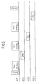
- FIG. 1 shows a network with eleven mobile stations according to the invention and three base stations according to the invention, and the process according to the invention is illustrated on the basis of the network.
- FIG. 2 shows the course of transmission before a handover procedure.
- FIG. 3 shows the course of transmission during the handover procedure.
- FIG. 4 shows the course of transmission after the handover procedure.
- FIG. 5 shows a transmission procedure in detail.
- FIG. 1 In FIG. 1 , four mobile stations MS 1 to MS 4 are seen, which are in a WLAN radio link W with an access point AP 1 . Correspondingly, three mobile stations MS 5 to MS 7 are in a WLAN radio link W with an access point AP 2 , and four mobile stations MS 8 to MS 11 with an access point AP 3 .
- the WLAN radio links W can for example be effected in accordance with the standard IEEE 802.11a, b or g with HCF-QoS extensions in accordance with IEEE 802.11e.
- the radio transmission takes place for example in the MHz or GHz range.
- the three access points AP 1 , AP 2 and AP 3 are each connected to a central switch ZS (switching device), which is connected to a public telephone network PSTN and/or to the internet.
- the links between the central switch ZS and the access points AP 1 , AP 2 and AP 3 on the one hand and the link between the central switch ZS and the public telephone network on the other are each for example constituted by a synchronous interface SY (e.g. ISDN-SO or UpO interface) or a packet-oriented interface with appropriate QoS precautions.
- Data streams D for example in the kHz range (e.g. telephone link) are transmitted via these interfaces SY.
- the data packets for the WLAN link path W are created with “beacon-triggering” both in the access points AP 1 to AP 3 and also in the mobile stations MS 1 to MS 11 .
- the data stream D is subdivided into packets, the packet content whereof always corresponds to the data content in one time window, the time window duration whereof is equal to double the time interval between two directly consecutive beacon signals. Transmission of the data packets between the access points AP 1 to AP 3 and the respective assigned mobile stations MS 1 to MS 11 therefore takes place each time only in every second transmission phase; every second transmission phase is thus omitted.
- the mobile station MS 2 must seek another access point with better transmission quality and create a link with this. Since different frequencies are assigned to different access points, the mobile station MS 2 must retune on a trial basis to another frequency, wait for a beacon on this frequency and, if one is found, record the associated signal quality, for example the signal strength. By repetition of this “scan procedure” at different frequencies, a table of possible access points is built up, in order then to seek the optimal access point as the target of the handover.
- the access points AP 1 to AP 3 are not mutually synchronised.
- the beacons (short for beacon signals) of the different access points are thus in any time position relative to one another, although they each display the same beacon repeat rate or the same beacon interval BA (see FIG. 2 ).
- the transmission phases of the access points AP 1 to AP 3 may overlap.
- the mobile station MS 2 Since the mobile station MS 2 cannot know the time shift of the beacon signals, it must, with a beacon signal interval of for example 10.24 msecs, listen at the new frequency in question for at least ca. 10 msecs in order to intercept a possible beacon signal. This could lead to an interruption in the data stream, since in the period in which the mobile station MS 2 is tuned to another frequency no data can be transmitted to the old, original access point AP 1 .
- each access point AP 1 to AP 3 divides the transmission phases in such a manner that each assigned mobile station omits at least one transmission phase each time after each utilised transmission phase. For example, each mobile station sends and receives data packets only in every second period.
- FIG. 2 This is shown by way of example in FIG. 2 , in which the time sequence of the data packet transmission between the access points AP 1 to AP 3 and the mobile stations MS 1 to MS 11 is shown.
- a “A” symbol represents a transmission in the mobile station direction and the symbol rotated through 180° a transmission in the access point direction.
- the beacon signals are marked with the symbol B and have a beacon interval BA of for example 10.24 msecs.
- the transmission phase, or “contention-free period”, triggered by the beacon signal B is marked in FIG. 2 by the symbol U.
- Each transmission phase U is followed each time by a transmission pause (“contention period”) F, in which the air path is released for the frequency range in question.
- each mobile station MS 1 to MS 13 [sic] each uses only every second transmission phase, the quantity of data per transmission phase each time is doubled, compared to a “normal” transmission in every transmission phase, in order to obtain the required mean data rate.
- the mobile stations assigned to each access point are preferably evenly apportioned to the “even” and “odd” beacons or transmission phases, in order to attain an even loading of the transmission phases.
- the mobile station MS 2 Since only every second transmission phase relative to the access point AP 1 is used, the mobile station MS 2 has sufficient time between the data transmissions to the assigned access point AP 1 to retune to another frequency, to seek a beacon there, and tune back to the old frequency in good time.
- the central point is that the beacon period is still always 10.24 msecs, although the interval between the transmission phases actually used is doubled, compared to the “normal” use of all transmission phases.
- the time interval between two consecutive beacon signals is at least twice as large as the length of the contention-free period U lying between them; this means that the transmission phases may last a maximum of 5.12 msecs each time.
- the duration of the monitoring phase M of the mobile station MS 2 can be 1.5 times the time interval between two consecutive beacon signals, i.e. ca. 15 msecs. Accordingly, in this monitoring phase of 15 msecs at least one beacon on the new frequency must be recognisable, irrespective of how the beacons of the three unsynchronised access points AP 1 to AP 3 are displaced relative to one another, because the beacon interval at all access points is 10.24 msecs in each case.
- the mobile station MS 2 scans the air interface at different frequencies for available access points. If for example in the process it is established that the access point AP 2 is suitable for a handover procedure, then the mobile station MS 2 will create a parallel data link with the new access point AP 2 . This is shown in detail in FIG. 3 .
- the assignment to the “even” or “odd” beacon at the new frequency of the new access point AP 2 is selected in such a manner that in fact two parallel data streams are possible; this means for example that the mobile station MS 2 must select an “odd” transmission phase in relation to the new access point AP 2 , if it is in an “even” transmission phase in relation to the old, original access point AP 1 .
- the mobile station MS 2 In the handover phase, the mobile station MS 2 on average transmits data every 10.24 msecs, which is alternately directed to the old and the new access point.
- FIG. 5 the data link between the access point AP 1 and the three mobile stations MS 1 to MS 3 in the “first” transmission phase according to FIG. 2 is shown once again. It can be seen that the access point AP 1 firstly passes data packets “DATA” to the mobile station MS 1 . As soon as this process is completed, data packets “DATA” are requested from the mobile station MS 1 by means of a signal CF-Poll. Next, this process of the sending and “requesting” of data packets is repeated with the mobile stations MS 2 and MS 3 .
- the “contention-free periods” can for example be ended by a contention-free end signal CF-end.
- the data packets “DATA” always contain a data content which corresponds in time to double the time interval BA between two directly consecutive beacons signals.
- the data packets “DATA” thus contain data of the data stream D for a time period of 2*BA.
Landscapes
- Engineering & Computer Science (AREA)
- Computer Networks & Wireless Communication (AREA)
- Signal Processing (AREA)
- Mobile Radio Communication Systems (AREA)
- Communication Control (AREA)
Applications Claiming Priority (4)
| Application Number | Priority Date | Filing Date | Title |
|---|---|---|---|
| DE102004026487A DE102004026487B4 (de) | 2004-05-27 | 2004-05-27 | Verfahren zum Betreiben einer Datenverbindung |
| DE102004026487.2 | 2004-05-27 | ||
| DE102004026487 | 2004-05-27 | ||
| PCT/DE2005/000975 WO2005117351A1 (de) | 2004-05-27 | 2005-05-26 | Verfahren zum betreiben einer datenverbindung |
Publications (2)
| Publication Number | Publication Date |
|---|---|
| US20080049685A1 US20080049685A1 (en) | 2008-02-28 |
| US7961619B2 true US7961619B2 (en) | 2011-06-14 |
Family
ID=34971772
Family Applications (1)
| Application Number | Title | Priority Date | Filing Date |
|---|---|---|---|
| US11/597,846 Active 2027-12-05 US7961619B2 (en) | 2004-05-27 | 2005-05-26 | Process for operation of a data link |
Country Status (8)
| Country | Link |
|---|---|
| US (1) | US7961619B2 (de) |
| EP (1) | EP1749373B1 (de) |
| AT (1) | ATE480069T1 (de) |
| CA (1) | CA2569547C (de) |
| DE (2) | DE102004026487B4 (de) |
| ES (1) | ES2351512T3 (de) |
| TW (1) | TW200605696A (de) |
| WO (1) | WO2005117351A1 (de) |
Families Citing this family (8)
| Publication number | Priority date | Publication date | Assignee | Title |
|---|---|---|---|---|
| DE102005006399A1 (de) * | 2005-02-11 | 2006-08-24 | Siemens Ag | Verfahren zur Steuerung einer Signalübertragung in einem Funk-Kommunikationssystem |
| DE102009031995A1 (de) | 2009-07-06 | 2011-01-13 | Neutrik Aktiengesellschaft | Verfahren zur drahtlosen Echtzeitübertragung zumindest eines Audiosignales |
| US9148250B2 (en) | 2012-06-30 | 2015-09-29 | Intel Corporation | Methods and arrangements for error correction in decoding data from an electromagnetic radiator |
| US9218532B2 (en) | 2012-09-28 | 2015-12-22 | Intel Corporation | Light ID error detection and correction for light receiver position determination |
| US9178615B2 (en) * | 2012-09-28 | 2015-11-03 | Intel Corporation | Multiphase sampling of modulated light with phase synchronization field |
| US9590728B2 (en) | 2012-09-29 | 2017-03-07 | Intel Corporation | Integrated photogrammetric light communications positioning and inertial navigation system positioning |
| US10951292B2 (en) | 2018-01-26 | 2021-03-16 | California Institute Of Technology | Systems and methods for random access communication |
| WO2019183601A1 (en) * | 2018-03-22 | 2019-09-26 | California Institute Of Technology | Coded random access mechanism for communication networks |
Citations (8)
| Publication number | Priority date | Publication date | Assignee | Title |
|---|---|---|---|---|
| US6332077B1 (en) | 1999-07-29 | 2001-12-18 | National Datacom Corporation | Intelligent roaming in AGV application |
| US20030148767A1 (en) | 2001-05-08 | 2003-08-07 | Shigeru Sugaya | Radio communication system, control station, communication apparatus, communication control method, radio communciation method, and communication control program |
| US20040068668A1 (en) * | 2002-10-08 | 2004-04-08 | Broadcom Corporation | Enterprise wireless local area network switching system |
| US20040066783A1 (en) | 2002-09-26 | 2004-04-08 | Deepak Ayyagari | Connection management in a centralized communication system |
| US20050190731A1 (en) * | 2004-03-01 | 2005-09-01 | Yigal Bejerano | Methods and devices for providing a relative level of fairness and QoS guarantees to wireless local area networks |
| US6980810B1 (en) * | 2003-05-12 | 2005-12-27 | At&T Corp. | Point coordinated spread-spectrum wireless local area network |
| US6990116B1 (en) * | 2001-01-12 | 2006-01-24 | 3Com Corporation | Method and system for improving throughput over wireless local area networks with mode switching |
| US7457973B2 (en) * | 2003-06-20 | 2008-11-25 | Texas Instruments Incorporated | System and method for prioritizing data transmission and transmitting scheduled wake-up times to network stations based on downlink transmission duration |
-
2004
- 2004-05-27 DE DE102004026487A patent/DE102004026487B4/de not_active Expired - Fee Related
-
2005
- 2005-05-26 US US11/597,846 patent/US7961619B2/en active Active
- 2005-05-26 DE DE502005010178T patent/DE502005010178D1/de active Active
- 2005-05-26 CA CA2569547A patent/CA2569547C/en active Active
- 2005-05-26 AT AT05757049T patent/ATE480069T1/de active
- 2005-05-26 WO PCT/DE2005/000975 patent/WO2005117351A1/de active Application Filing
- 2005-05-26 ES ES05757049T patent/ES2351512T3/es active Active
- 2005-05-26 EP EP05757049A patent/EP1749373B1/de active Active
- 2005-05-27 TW TW094117544A patent/TW200605696A/zh unknown
Patent Citations (8)
| Publication number | Priority date | Publication date | Assignee | Title |
|---|---|---|---|---|
| US6332077B1 (en) | 1999-07-29 | 2001-12-18 | National Datacom Corporation | Intelligent roaming in AGV application |
| US6990116B1 (en) * | 2001-01-12 | 2006-01-24 | 3Com Corporation | Method and system for improving throughput over wireless local area networks with mode switching |
| US20030148767A1 (en) | 2001-05-08 | 2003-08-07 | Shigeru Sugaya | Radio communication system, control station, communication apparatus, communication control method, radio communciation method, and communication control program |
| US20040066783A1 (en) | 2002-09-26 | 2004-04-08 | Deepak Ayyagari | Connection management in a centralized communication system |
| US20040068668A1 (en) * | 2002-10-08 | 2004-04-08 | Broadcom Corporation | Enterprise wireless local area network switching system |
| US6980810B1 (en) * | 2003-05-12 | 2005-12-27 | At&T Corp. | Point coordinated spread-spectrum wireless local area network |
| US7457973B2 (en) * | 2003-06-20 | 2008-11-25 | Texas Instruments Incorporated | System and method for prioritizing data transmission and transmitting scheduled wake-up times to network stations based on downlink transmission duration |
| US20050190731A1 (en) * | 2004-03-01 | 2005-09-01 | Yigal Bejerano | Methods and devices for providing a relative level of fairness and QoS guarantees to wireless local area networks |
Non-Patent Citations (3)
| Title |
|---|
| English translation of International Preliminary Report on Patentability corresponding to PCT/DE2005/000975. |
| Grieco, et al., "A Control Theoretic Approach for supporting Quality of Service in IEEE 802.11e WLANs with HCF 1" Proceedings of the 42nd IEEE Conference on Decision and Control, Maui, HI, Dec. 2003, vol. 1 of 6, Conf. 42, pp. 1586-1591, XP010685880. |
| Shirdokar, et al., "A QoS-based Indoor Wireless Data Network Design for VoIP Applications" VTC Fall 2001, IEEE 54th, Vehicular Technology Conference Proceedings, Atlantic City, NJ, Oct. 7, 2001, vol. 1 of 4, Conf. 54, pp. 2594-2598, XP010562442. |
Also Published As
| Publication number | Publication date |
|---|---|
| TW200605696A (en) | 2006-02-01 |
| DE502005010178D1 (de) | 2010-10-14 |
| EP1749373A1 (de) | 2007-02-07 |
| CA2569547A1 (en) | 2005-12-08 |
| DE102004026487B4 (de) | 2007-03-29 |
| DE102004026487A1 (de) | 2005-12-22 |
| ATE480069T1 (de) | 2010-09-15 |
| EP1749373B1 (de) | 2010-09-01 |
| US20080049685A1 (en) | 2008-02-28 |
| CA2569547C (en) | 2014-09-30 |
| ES2351512T3 (es) | 2011-02-07 |
| WO2005117351A1 (de) | 2005-12-08 |
Similar Documents
| Publication | Publication Date | Title |
|---|---|---|
| US7961619B2 (en) | Process for operation of a data link | |
| US7583648B2 (en) | Managing latency and jitter on wireless LANs | |
| EP1642419B1 (de) | Verfahren zur dezentralisierten mediumzugriffsregelung in einem kommunikationsnetz | |
| US7356010B2 (en) | Point coordinator control passing scheme using a scheduling information parameter set for an IEEE 802.11 wireless local area network | |
| KR101403342B1 (ko) | 무선 비디오 영역 네트워크를 위한 채널 설정 방법 및시스템 | |
| US5329531A (en) | Method of accessing a communication medium | |
| KR100452667B1 (ko) | 무선통신시스템에서신호강도측정장치및그방법 | |
| US7280555B2 (en) | System and method employing algorithms and protocols for optimizing carrier sense multiple access (CSMA) protocols in wireless networks | |
| JP5200022B2 (ja) | 無線アドホックネットワークにおけるマルチチャネルmacプロトコルに対する効率的なチャネルアーキテクチャ | |
| EP1798898A1 (de) | Wahl eines Zugangsknotens zum Senden von Empfangsbestätigungen an ein drahtloses Netzwerk | |
| AU2005226531B2 (en) | Method of signaling reverse channel information with minimal voice/data delay | |
| KR20040104219A (ko) | 무선 통신 시스템에서 근거리 통신 시스템 및 방법 | |
| US7623448B1 (en) | Systems and methods for wireless network negotiation | |
| JPH08510608A (ja) | Tdma通信システム | |
| US20080273495A1 (en) | Smooth Handover in a Wireless Local Area Network | |
| EP2308176A1 (de) | Verfahren zur erweiterung eines heterogenen mac-protokolls auf mehrkanalsysteme | |
| US20080132233A1 (en) | Method for Operating Two Radio Communication Systems | |
| US6788665B1 (en) | Method and apparatus using alternate frames for handover in TDMA mobile communications system | |
| JP4086385B2 (ja) | データ伝送方法およびデータ伝送システム並びに当該システムに用いる装置 | |
| CN102308646A (zh) | 无线通信装置及系统 | |
| GB2292048A (en) | Communications device with adaptive burst transmission time to avoid periodic interference | |
| WO2010041127A1 (en) | Method and apparatus for communicating over multiple networks | |
| Chen et al. | Hmc: a hopping-based multi-channel coordination scheme for urllc in unlicensed spectrum | |
| JP2007074214A (ja) | 無線パケットスケジューリング拡張方法および無線基地局装置 | |
| JP5053231B2 (ja) | 無線通信方法および無線通信システムならびに基地局 |
Legal Events
| Date | Code | Title | Description |
|---|---|---|---|
| AS | Assignment |
Owner name: DETEWE SYSTEMS GMBH, GERMANY Free format text: ASSIGNMENT OF ASSIGNORS INTEREST;ASSIGNORS:BECKER, THOMAS;KRAUSE, FRANK-MICHAEL;METHFESSEL, MICHAEL;AND OTHERS;REEL/FRAME:019659/0554;SIGNING DATES FROM 20070109 TO 20070122 Owner name: IHP GMBH, GERMANY Free format text: ASSIGNMENT OF ASSIGNORS INTEREST;ASSIGNORS:BECKER, THOMAS;KRAUSE, FRANK-MICHAEL;METHFESSEL, MICHAEL;AND OTHERS;REEL/FRAME:019659/0554;SIGNING DATES FROM 20070109 TO 20070122 Owner name: DETEWE SYSTEMS GMBH, GERMANY Free format text: ASSIGNMENT OF ASSIGNORS INTEREST;ASSIGNORS:BECKER, THOMAS;KRAUSE, FRANK-MICHAEL;METHFESSEL, MICHAEL;AND OTHERS;SIGNING DATES FROM 20070109 TO 20070122;REEL/FRAME:019659/0554 Owner name: IHP GMBH, GERMANY Free format text: ASSIGNMENT OF ASSIGNORS INTEREST;ASSIGNORS:BECKER, THOMAS;KRAUSE, FRANK-MICHAEL;METHFESSEL, MICHAEL;AND OTHERS;SIGNING DATES FROM 20070109 TO 20070122;REEL/FRAME:019659/0554 |
|
| STCF | Information on status: patent grant |
Free format text: PATENTED CASE |
|
| AS | Assignment |
Owner name: AASTRA DETEWE GMBH, GERMANY Free format text: CHANGE OF NAME;ASSIGNOR:DETEWE SYSTEMS GMBH;REEL/FRAME:027531/0199 Effective date: 20061123 Owner name: AASTRA DEUTSCHLAND GMBH, GERMANY Free format text: CHANGE OF NAME;ASSIGNOR:AASTRA DETEWE GMBH;REEL/FRAME:027531/0242 Effective date: 20091210 |
|
| FPAY | Fee payment |
Year of fee payment: 4 |
|
| FEPP | Fee payment procedure |
Free format text: PAYOR NUMBER ASSIGNED (ORIGINAL EVENT CODE: ASPN); ENTITY STATUS OF PATENT OWNER: LARGE ENTITY |
|
| AS | Assignment |
Owner name: MITEL NETWORKS CORPORATION, CANADA Free format text: MERGER AND CHANGE OF NAME;ASSIGNORS:AASTRA TECHNOLOGIES LIMITED;AASTRA TECHNOLOGIES LIMITED;REEL/FRAME:035118/0257 Effective date: 20140131 |
|
| AS | Assignment |
Owner name: BANK OF AMERICA, N.A.(ACTING THROUGH ITS CANADA BR Free format text: SECURITY INTEREST;ASSIGNOR:MITEL NETWORKS CORPORATION;REEL/FRAME:035783/0540 Effective date: 20150429 |
|
| AS | Assignment |
Owner name: MITEL DEUTSCHLAND GMBH, GERMANY Free format text: CHANGE OF NAME;ASSIGNOR:AASTRA DEUTSCHLAND GMBH;REEL/FRAME:035899/0594 Effective date: 20140925 |
|
| AS | Assignment |
Owner name: MITEL US HOLDINGS, INC., ARIZONA Free format text: RELEASE BY SECURED PARTY;ASSIGNORS:BANK OF AMERICA, N.A., AS COLLATERAL AGENT;BANK OF AMERICA, N.A., (ACTING THROUGH ITS CANADA BRANCH), AS CANADIAN COLLATERAL AGENT;REEL/FRAME:042244/0461 Effective date: 20170309 Owner name: MITEL BUSINESS SYSTEMS, INC., ARIZONA Free format text: RELEASE BY SECURED PARTY;ASSIGNORS:BANK OF AMERICA, N.A., AS COLLATERAL AGENT;BANK OF AMERICA, N.A., (ACTING THROUGH ITS CANADA BRANCH), AS CANADIAN COLLATERAL AGENT;REEL/FRAME:042244/0461 Effective date: 20170309 Owner name: MITEL COMMUNICATIONS, INC., TEXAS Free format text: RELEASE BY SECURED PARTY;ASSIGNORS:BANK OF AMERICA, N.A., AS COLLATERAL AGENT;BANK OF AMERICA, N.A., (ACTING THROUGH ITS CANADA BRANCH), AS CANADIAN COLLATERAL AGENT;REEL/FRAME:042244/0461 Effective date: 20170309 Owner name: MITEL NETWORKS, INC., ARIZONA Free format text: RELEASE BY SECURED PARTY;ASSIGNORS:BANK OF AMERICA, N.A., AS COLLATERAL AGENT;BANK OF AMERICA, N.A., (ACTING THROUGH ITS CANADA BRANCH), AS CANADIAN COLLATERAL AGENT;REEL/FRAME:042244/0461 Effective date: 20170309 Owner name: MITEL (DELAWARE), INC., ARIZONA Free format text: RELEASE BY SECURED PARTY;ASSIGNORS:BANK OF AMERICA, N.A., AS COLLATERAL AGENT;BANK OF AMERICA, N.A., (ACTING THROUGH ITS CANADA BRANCH), AS CANADIAN COLLATERAL AGENT;REEL/FRAME:042244/0461 Effective date: 20170309 Owner name: MITEL NETWORKS CORPORATION, CANADA Free format text: RELEASE BY SECURED PARTY;ASSIGNORS:BANK OF AMERICA, N.A., AS COLLATERAL AGENT;BANK OF AMERICA, N.A., (ACTING THROUGH ITS CANADA BRANCH), AS CANADIAN COLLATERAL AGENT;REEL/FRAME:042244/0461 Effective date: 20170309 |
|
| MAFP | Maintenance fee payment |
Free format text: PAYMENT OF MAINTENANCE FEE, 8TH YEAR, LARGE ENTITY (ORIGINAL EVENT CODE: M1552); ENTITY STATUS OF PATENT OWNER: LARGE ENTITY Year of fee payment: 8 |
|
| MAFP | Maintenance fee payment |
Free format text: PAYMENT OF MAINTENANCE FEE, 12TH YEAR, LARGE ENTITY (ORIGINAL EVENT CODE: M1553); ENTITY STATUS OF PATENT OWNER: LARGE ENTITY Year of fee payment: 12 |