US7826935B2 - Processing unit for generating control signal, controller with the processing unit for controlling actuator, and program executed in the processing unit - Google Patents
Processing unit for generating control signal, controller with the processing unit for controlling actuator, and program executed in the processing unit Download PDFInfo
- Publication number
- US7826935B2 US7826935B2 US11/730,998 US73099807A US7826935B2 US 7826935 B2 US7826935 B2 US 7826935B2 US 73099807 A US73099807 A US 73099807A US 7826935 B2 US7826935 B2 US 7826935B2
- Authority
- US
- United States
- Prior art keywords
- point
- floating
- control
- control parameter
- fixed
- Prior art date
- Legal status (The legal status is an assumption and is not a legal conclusion. Google has not performed a legal analysis and makes no representation as to the accuracy of the status listed.)
- Expired - Fee Related, expires
Links
Images


Classifications
-
- G—PHYSICS
- G05—CONTROLLING; REGULATING
- G05B—CONTROL OR REGULATING SYSTEMS IN GENERAL; FUNCTIONAL ELEMENTS OF SUCH SYSTEMS; MONITORING OR TESTING ARRANGEMENTS FOR SUCH SYSTEMS OR ELEMENTS
- G05B19/00—Programme-control systems
- G05B19/02—Programme-control systems electric
- G05B19/04—Programme control other than numerical control, i.e. in sequence controllers or logic controllers
- G05B19/042—Programme control other than numerical control, i.e. in sequence controllers or logic controllers using digital processors
- G05B19/0428—Safety, monitoring
-
- F—MECHANICAL ENGINEERING; LIGHTING; HEATING; WEAPONS; BLASTING
- F02—COMBUSTION ENGINES; HOT-GAS OR COMBUSTION-PRODUCT ENGINE PLANTS
- F02D—CONTROLLING COMBUSTION ENGINES
- F02D2250/00—Engine control related to specific problems or objectives
- F02D2250/18—Control of the engine output torque
-
- F—MECHANICAL ENGINEERING; LIGHTING; HEATING; WEAPONS; BLASTING
- F02—COMBUSTION ENGINES; HOT-GAS OR COMBUSTION-PRODUCT ENGINE PLANTS
- F02D—CONTROLLING COMBUSTION ENGINES
- F02D41/00—Electrical control of supply of combustible mixture or its constituents
- F02D41/22—Safety or indicating devices for abnormal conditions
-
- F—MECHANICAL ENGINEERING; LIGHTING; HEATING; WEAPONS; BLASTING
- F02—COMBUSTION ENGINES; HOT-GAS OR COMBUSTION-PRODUCT ENGINE PLANTS
- F02D—CONTROLLING COMBUSTION ENGINES
- F02D41/00—Electrical control of supply of combustible mixture or its constituents
- F02D41/24—Electrical control of supply of combustible mixture or its constituents characterised by the use of digital means
- F02D41/26—Electrical control of supply of combustible mixture or its constituents characterised by the use of digital means using computer, e.g. microprocessor
Definitions
- the present invention relates to a processing unit for generating a control signal indicating a quantity of control, a controller with the processing unit for controlling an actuator to give the quantity of control to a controlled object of a vehicle according to the control signal, and a program executed in the processing unit to generate the control signal.
- a controller with a processing unit is disposed on a vehicle to control actuators. Sensors of the vehicle detect physical values as detected parameters, and the processing unit generates control parameters from the detected parameters. Each control parameter indicates a quantity of control for a controlled object. The controller outputs the control parameters to the respective actuators, and each actuator gives a quantity of control to the corresponding controlled object according to the control parameter.
- the processing unit has recently performed floating-point calculations in addition to fixed-point calculations.
- control unit When the processing unit performs both the fixed-point calculation and floating-point calculation, it is required to use fixed-point data and floating-point data in the processing unit. In this case, a volume of calculations is extraordinary increased in the processing unit.
- This control unit has a floating-point processor in addition to a central processing unit.
- the floating-point processor performs floating-point calculations to calculate floating-point data from detected parameters and transmits the floating-point data to the control unit.
- the control unit performs fixed-point calculations to calculate fixed-point data from other detected parameters. Then, the control unit can output the floating-point data to a part of actuators and output the fixed-point data to the other actuators. Therefore, each actuator can give a quantity of control to a controlled object according to the fixed-point data or floating-point data.
- An object of the present invention is to provide, with due consideration to the drawbacks of the conventional control unit, a processing unit which correctly generates a control signal while reliably detecting a failure occurring in a floating-point processor. Further, the object is to provide a controller with the processing unit which controls an actuator to give a quantity of control to a controlled object according to the control signal. Moreover, the object is to provide a computer program executed in the processing unit.
- the object is achieved by the provision of a processing unit comprising a parameter receiving section which receives a floating-point control parameter being generated in a floating-point processor from a detected parameter on the basis of a floating-point calculation and indicating a first quantity of control for a controlled object, a parameter generating section which receives the detected parameter and generates a fixed-point control parameter indicating a second quantity of control for the controlled object from the detected parameter on the basis of a fixed-point calculation, a converting section which converts the floating-point control parameter of floating-point representation into a converted control parameter of fixed-point representation, a failure judging section which judges from both the converted control parameter and the fixed-point control parameter whether or not a failure has occurred in the floating-point processor, a signal generating section which generates a control signal from the floating-point control parameter when no failure has occurred in the floating-point processor, and a signal outputting section which outputs the control signal to an actuator.
- the floating-point control parameter is determined so as to have a higher precision than the fixed-point control parameter.
- the floating-point and fixed-point control parameters generated from the detected parameter together become similar to each other.
- the floating-point control parameter becomes considerably different from the fixed-point control parameter. Therefore, it can be judged from both the converted control parameter and the fixed-point control parameter whether or not a failure has occurred in the floating-point processor.
- the signal generating section When the failure judging section judges that no failure has occurred in the floating-point processor, the signal generating section generates a control signal from the floating-point control parameter, and the signal outputting section outputs the control signal to an actuator.
- the actuator is operated according to the control signal, so that the actuator gives the first quantity of control to the controlled object.
- the processing unit can reliably use the floating-point control parameter obtained from the normally-operated floating-point processor, the processing unit can correctly generate a control signal with higher precision.
- the object is achieved by the provision of a controller comprising the processing unit and a floating-point processor.
- the floating-point processor is adapted to receive the detected parameter and generate the floating-point control parameter indicating the first quantity of control from the detected parameter on the basis of the floating-point calculation.
- the controller can control an actuator such that the actuator gives the first quantity of control to a controlled object according to the control signal correctly generated in the processing unit.
- the object is achieved by the provision of a computer program comprising a control parameter receiving segment receiving a floating-point control parameter which is generated from a detected parameter in a floating-point processor on the basis of a floating-point calculation and indicates a first quantity of control, a control parameter generating segment generating a fixed-point control parameter indicating a second quantity of control from the detected parameter on the basis of a fixed-point calculation, a converting segment converting the floating-point control parameter of floating-point representation into a converted control parameter of fixed-point representation, a judging segment judging from both the converted control parameter and the fixed-point control parameter whether or not a failure has occurred in the floating-point processor, a control signal generating segment generating a control signal from the floating-point control parameter when it is judged that no failure has occurred in the floating-point processor, and an outputting segment outputting the control signal to an actuator such that the actuator controls a controlled object by the first quantity of control.
- the processing unit can correctly generate a control signal by executing the program.
- FIG. 1 is a block diagram of an engine control system and an engine according to an embodiment of the present invention
- FIG. 2 is a block diagram of a CPU of a controller shown in FIG. 1 ;
- FIG. 3 is a block diagram of an FPU of a controller shown in FIG. 1 ;
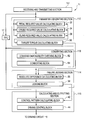
- FIG. 4 is a flowchart showing the procedure of an actuator control operation of the controller according to the embodiment.
- FIG. 5 is a flow chart showing the procedure of a failure detecting operation performed in the control operation shown in FIG. 4 ;
- FIG. 6 is a flow chart showing the procedure of a failure detecting operation performed in the CPU according to a first modification of the embodiment
- FIG. 7 is a flow chart showing the procedure of a conversion possibility judging operation according to a second modification of the embodiment.
- FIG. 8 is a flow chart showing the procedure of a failure detecting operation according to the second modification.
- FIG. 1 is a block diagram of an engine control system and an engine according to an embodiment of the present invention.
- an engine 100 of a vehicle representing a controlled object is operated under control of an engine control system.
- the engine 100 is formed of a fuel injection type internal combustion engine having a plurality of cylinders.
- the engine control system has a plurality of sensors 200 , an electric control unit (ECU) 1 , and an actuator composed of an injector driving circuit 110 and injectors 120 .
- the sensors 200 detect respective physical quantities indicating operation conditions of the engine 100 and running conditions of the vehicle and output detected parameters relating to the physical quantities to the ECU 1 .
- the ECU 1 has a controller 10 formed of a microcomputer.
- the controller 10 has a central processing unit (CPU) 11 , a read only memory (ROM) 13 , a random access memory (RAM) 15 , a floating-point processing unit (FPU) 17 and an input-output port (I/O) 19 .
- a plurality of computer programs such as processing programs and control programs are stored in advance in the ROM 13 .
- Data and parameters used and obtained in the CPU 11 and FPU 17 are stored in the RAM 15 .
- the controller 10 receives the detected parameters from the sensors 200 through the I/O port 19 .
- sensors 200 such as an acceleration stroke sensor, an engine speed sensor, a crank sensor, a water temperature sensor and the like.
- the acceleration stroke sensor 200 detects a stroke position of an accelerator pedal operated by a driver of the vehicle.
- the engine speed sensor 200 detects a number of revolutions in the engine 100 .
- the crank sensor 200 detects an angle of a crank.
- the water temperature sensor detects a temperature of a cooling water used for the engine 100 .
- the CPU 11 and FPU 17 execute the programs of the ROM 13 for the arithmetic processing.
- the CPU 11 performs fixed-point calculations based on the detected parameters and generates a control parameter of the fixed-point expression.
- the FPU 17 performs floating-point calculations based on the detected parameters received from the CPU 11 and generates a control parameter of the floating-point expression.
- the CPU 11 judges from the control parameters whether or not a failure has occurred in the FPU 17 . When the CPU 11 judges that no failure has occurred in the FPU 17 , the CPU 11 generates a driving control signal from the control parameter of the floating-point expression.
- the control signal is transmitted to an actuator, and the actuator is operated according to the control signal so as to give a quantity of control to a controlled object.
- the driving circuit 110 receives the control signal and determines a control quantity of fuel to be injected from the injectors 120 for each revolution cycle of the engine 100 , and the injectors 120 driven by the driving circuit 110 discharge the control quantity of fuel to the respective cylinders of the engine 100 . Therefore, the engine 100 is operated at an optimum fuel economy under control of the ECU 1 .
- FIG. 2 is a block diagram of the CPU 11 according to the embodiment
- FIG. 3 is a block diagram of the FPU 17 according to the embodiment.
- the CPU 11 has a receiving and transmitting section 111 , a parameter generating section 112 , a converting section 113 , a failure judging section 114 , and a calculating and outputting section 115 .
- the section 111 receives detected parameters from the sensors 200 , transmits the detected parameters to the FPU 17 to cause the FPU 17 to generate a floating-point control parameter relating to a first quantity of control for the injectors 120 from the detected parameters on the basis of floating-point calculations, and receives the floating-point control parameter from the FPU 17 .
- the reception of this parameter is performed by executing a control parameter receiving segment of a computer program for generating a control signal, and this program is loaded in the CPU 11 .
- the section 112 generates a fixed-point control parameter relating to a second quantity of control for the injectors 120 from the detected parameters on the basis of fixed-point calculations.
- the generation of this parameter is performed by executing a control parameter generating segment of the computer program.
- the section 113 converts the floating-point control parameter of the floating-point representation into a converted control parameter of the fixed-point representation. This conversion is performed by executing a converting segment of the computer program.
- the section 114 compares the converted control parameter with the fixed-point control parameter of the fixed-point representation to obtain a comparison result and judges from the comparison result whether or not a failure or fault occurs in the FPU 17 .
- the section 114 judges that the FPU 17 is normally operated, the section 114 outputs a normal operation signal to the section 115 .
- the section 114 judges that a failure has occurred in the FPU 17 , the section 114 outputs a fail-safe operation signal to the section 115 .
- the section 115 In response to the normal operation signal, the section 115 generates a normal control signal indicating the first quantity of control from the floating-point control parameter and outputs this signal to an actuator.
- the actuator is operated according to the normal control signal so as to give the first quantity of control to a controlled object.
- the driving circuit 110 receives the normal control signal, and the injectors 120 driven by the driving circuit 110 inject a controlled quantity of fuel into the engine 100 .
- This generation of the control signal is performed by executing a control signal generating segment of the computer program, and the outputting of the signal is performed by executing an outputting segment of the computer program.
- the section 115 in response to the fail-safe operation signal, the section 115 generates a fail-safe control signal indicating a fail-safe quantity of control and outputs this signal to an actuator.
- the actuator is operated according to the fail-safe control signal so as to give the fail-safe quantity of control to a controlled object.
- the driving circuit 110 receives the fail-safe control signal, and the injectors 120 driven by the driving circuit 110 inject a suitable quantity of fuel required of the engine 100 to safely drive the vehicle.
- the section 112 of the CPU 11 has a pedal required value calculating block 32 , a cruise required value calculating block 34 , an idling required value calculating block 36 , and a target torque calculating block 38 .
- the block 32 calculates a pedal required value at fixed-point calculations from a stroke position of an accelerator pedal representing a detected parameter.
- the pedal required value indicates a torque value required of the engine 100 to drive the vehicle in response to the driver's requirement.
- the block 34 calculates a cruise required value at fixed-point calculations from a target speed of the vehicle representing a detected parameter.
- the cruise required value indicates a torque value required of the engine 100 to keep driving the vehicle at the target speed.
- the block 36 calculates an idling required value at fixed-point calculations from data of idling which is stored in the RAM 15 and represents a detected parameter.
- the idling required value indicates a torque value required of the engine 100 to keep the vehicle in an idling condition.
- the block 38 adds the idling required value received from the block 36 to the pedal required value or the cruise required value received from the block 32 or 34 to obtain a target torque representing a fixed-point control parameter. This target torque is obtained based on the fixed-point calculations of the CPU 11 and is called a target torque based on CPU 11 .
- the block 38 outputs this target torque to the section 114 .
- the FPU 17 has a pedal required value calculating block 171 , a cruise required value calculating block 172 , an idling required value calculating block 173 , and a target torque calculating block 174 .
- the block 171 calculates a pedal required value from the stroke position of the accelerator pedal at floating-point calculations.
- the block 172 calculates a cruise required value from the target speed of the vehicle at floating-point calculations.
- the block 173 calculates an idling required value from the data of idling at floating-point calculations.
- the block 174 adds the idling required value to the pedal required value or the cruise required value to obtain a target torque of the floating-point representation. This target torque represents a floating-point control parameter.
- the FPU 17 transmits this target torque to the section 113 of the CPU 11 .
- Data of the floating-point representation is, for example, expressed by 4 bytes (32 bits) according to IEEE-754 Standard and has a sign part of 1 bit, an exponential part of 8 bits and a mantissa of 23 bits. Therefore, this floating-point representation has resolution of 7 digits (i.e., resolution of 0.0000001).
- the section 113 has a conversion possibility checking block 52 and a converting block 54 .
- the block 52 checks whether or not the target torque of the floating-point representation received from the FPU 17 can be expressed by fixed-point data of a predetermined fixed-point representation set at a predetermined data length. For example, when the fixed-point data is preset to be expressed by 2 bytes (i.e., 16 bits) at an offset set at zero, the target torque of the floating-point representation exceeding a value of 65536 (i.e., 2 16 ) or lower than zero cannot be converted into a value of the fixed-point representation.
- the block 54 converts the target torque of the floating-point representation into a converted target torque of the fixed-point representation when the block 52 judges that the target torque of the floating-point representation can be expressed by fixed-point data.
- This converted target torque represents a converted control parameter. Because this converted target torque is obtained based on the floating-point calculations of the FPU 17 , this target torque is called a target torque based on FPU 17 .
- LSB least significant bit
- the LSB data expresses a physical value corresponding to a lowest bit of fixed-point data.
- the offset data indicates a position of a base point (i.e., a value regarded as zero) in fixed-point data, and the base point divides the fixed-point data into an integral part and a decimal part.
- the offset data is set at a hexadecimal number “0x7FFF”. In this case, a hexadecimal number “0x0000” indicates a negative decimal number “ ⁇ 32767”, and a hexadecimal number “0xFFFF” indicates a decimal number “32768”.
- an offset value indicated by the offset data is added to the floating-point control parameter to obtain a non-offset value, the non-offset value is divided by a value of the LSB data to obtain a divided value, and a decimal part of the divided value is subtracted from the divided value to obtain an integral part of the divided value.
- the integral part of the divided value is output from the block 54 as a converted control parameter of fixed-point representation.
- the section 114 has an absolute difference calculating block 56 and a judging block 58 .
- the block 56 calculates an absolute value of a difference between the target torque based on FPU 17 and the target torque based on CPU 11 .
- the block 58 compares the absolute value obtained in the block 56 with a predetermined threshold value. This threshold value is set such that the absolute value can easily exceed the threshold value when a failure has occurred in the FPU 17 , and the threshold value can be arbitrarily set. In a case where the absolute value is larger than the threshold value, the block 58 judges that a failure has occurred in the FPU 17 and generates a fail-safe operation signal. In other cases, the block 58 judges that no failure has occurred in the FPU 17 and generates a normal operation signal.
- the block 32 obtains a value of 4013 (integral part of 156.78 ⁇ (10/256)) as a pedal required value of the fixed-point representation
- the block 36 obtains a value of 261 (integral part of 10.23 ⁇ (10/256)) as an idling required value of the fixed-point representation
- the block 54 obtains a value of 4275 (integral part of 167.01 ⁇ (10/256)) as a target torque based on FPU 17
- the block 58 judges that the FPU 17 is normally operated.
- the section 115 has a control pattern calculating block 42 and a driving control block 44 .
- the block 42 calculates an injection control pattern of fuel injected from the injectors 120 from the target torque of the floating-point representation received from the FPU 17 , and the block 44 generates a normal control signal indicating the control pattern and outputs this signal to the driving circuit 110 . Therefore, the injectors 120 driven by the driving circuit 110 inject fuel at the control pattern such that the engine 100 generates the target torque of the floating-point representation.
- the block 42 calculates a fail-safe injection pattern of fuel injected from the injectors 120 , and the block 44 generates a fail-safe control signal indicating the fail-safe injection pattern and outputs this signal to the driving circuit 110 . Therefore, the injectors 120 driven by the driving circuit 110 inject fuel at the fail-safe injection pattern such that the engine 100 generates a fail-safe torque so as to safely run the vehicle.
- an alarm may be displayed on a display of the vehicle, or the CPU 11 may inform a driver that a failure has occurred in the FPU 17 .
- FIG. 4 is a flow chart showing the procedure of an actuator control operation of the controller 10 according to the embodiment.
- step S 110 when a cruise setting section (not shown) of the vehicle is set to a cruise control, the section 111 of the CPU 11 receives data indicating a target speed of the vehicle from the cruise setting section as a detected parameter.
- the section 111 of the CPU 11 receives data indicating a stroke position of an accelerator pedal from the acceleration stroke sensor 200 as a detected parameter. Further, the section 111 of the CPU 11 reads out data of idling from the RAM 15 as another detected parameter.
- step S 120 the section 111 of the CPU 11 transmits the detected parameters to the FPU 17 .
- the FPU 17 when receiving the data of the target speed and the data of idling, calculates a cruise required value and an idling required value from the data at floating-point calculations.
- the FPU 17 calculates a pedal required value and an idling required value from the data at floating-point calculations.
- the FPU 17 calculates a target torque of the floating-point representation as a floating-point control parameter by adding the idling required value to the cruise required value or the pedal required value.
- the FPU 17 transmits the target torque of the floating-point representation to the CPU 11 .
- step S 150 the sections 112 , 113 and 114 of the CPU 11 perform a failure detecting operation based on the target torque of the floating-point representation and judges whether or not a failure has occurred in the FPU 17 .
- the procedure proceeds to a step S 160 . In other cases, the procedure proceeds to a step S 170 .
- the section 114 outputs a normal operation signal to the section 115 .
- the section 115 of the CPU 11 In response to the normal operation signal, the section 115 of the CPU 11 generates a normal control signal indicating a control quantity of fuel from the target torque of the floating-point representation received from the FPU 17 . Then, the CPU 11 outputs the normal control signal to the driving circuit 110 representing an actuator. Therefore, the injectors 120 representing the actuator inject a control quantity of fuel to the respective cylinders of the engine 110 representing a controlled object.
- the section 114 outputs a fail-safe operation signal to the section 115 .
- the section 115 In response to the fail-safe operation signal, the section 115 generates a fail-safe control signal indicating a suitable control quantity of fuel required of the engine 100 to safely drive the vehicle. Then, the CPU 11 outputs the fail-safe control signal to the driving circuit 110 . Therefore, the injectors 120 inject a suitable control quantity of fuel to the engine 110 .
- FIG. 5 is a flow chart showing a failure detecting operation performed at step S 150 in the CPU 11 according to the embodiment.
- step S 151 when the section 111 receives data of target speed and data of idling, the section 112 of the CPU 11 calculates a cruise required value and an idling required value from the data at fixed-point calculations.
- the section 112 calculates a pedal required value and an idling required value from the data at fixed-point calculations.
- the section 112 calculates a target torque of the fixed-point representation from the required values as a fixed-point control parameter. This target torque is called a target torque based on CPU 11 .
- step S 153 the section 113 of the CPU 11 judges whether or not the target torque of the floating-point representation received from the FPU 17 can be expressed at a fixed-point type.
- the procedure proceeds to a step S 154 .
- the failure detecting operation is finished.
- a control signal is, for example, generated from the target torque based on CPU 11 , and the driving circuit 110 and injectors 120 representing the actuator control the engine 100 according to the control signal.
- the section 113 of the CPU 11 converts the target torque of the floating-point representation into a target torque of the fixed-point representation.
- This target torque is called a target torque based on FPU 17 .
- the section 114 of the CPU 11 calculates an absolute value of a difference between the target torque based on FPU 17 and the target torque based on CPU 11 .
- the section 114 judges based on the absolute value whether or not a failure has occurred in the FPU 17 .
- the absolute value is larger than a predetermined threshold value
- the section 114 judges that a failure has occurred in the FPU 17 , and the procedure proceeds to step S 170 .
- the section 114 judges that the FPU 17 is normally operated, and the procedure proceeds to step S 160 .
- control signal is generated from the floating-point control parameter, the controller 10 can control the actuator with higher precision.
- the threshold value can be adjusted in dependence on conditions of the controller 10 in the vehicle, the failure detection can be performed with a precision suitable to the conditions of the controller 10 .
- the threshold value may be set at a comparatively large value to normally operate a controlled object regardless of the large error in the controller 10 .
- the threshold value may be set at a low value to detect a failure in the FPU 17 with high precision.
- the LSB data and the offset data are used for the conversion from floating-point data into fixed-point data, this conversion can be smoothly performed.
- the absolute value of the difference between the target torque based on FPU 17 and the target torque based on CPU 11 is compared with the threshold value, the occurrence of a failure in the FPU 17 can be judged at a constant judging criterion regardless of whether the target torque based on FPU 17 is larger or smaller than the target torque based on CPU 11 .
- the failure detecting operation is forcedly finished when at least one of the required values of the floating-point representation becomes out of a range for the fixed-point representation. Therefore, there is no probability that a target torque of the floating-point representation is erroneously converted into a target torque of the fixed-point representation. Accordingly, the CPU 11 can reliably prevent the occurrence of a failure in the FPU 17 being erroneously judged.
- the occurrence of a failure in the FPU 17 is judged based on a difference between the target torque based on CPU 11 and the target torque based on FPU 17 .
- the occurrence of a failure in the FPU 17 may be judged based on a difference between a fixed-point value obtained from at least one of the floating-point required values and the corresponding fixed-point required value obtained in the CPU 11 .
- the occurrence of a failure in the FPU 17 may be judged based on both a difference between the target torque based on CPU 11 and the target torque based on FPU 17 and a difference between a fixed-point value derived from one floating-point required value of the FPU 17 and the corresponding fixed-point required value obtained in the CPU 11 .
- the occurrence of a failure in the FPU 17 may be judged based on differences between a group of all required values calculated in the CPU 11 and a group of fixed-point required values derived from all floating-point required values of the FPU 17 .
- This modified failure detecting operation performed at step S 150 in the CPU 11 is described with reference to FIG. 6 .
- a target torque based on CPU 11 is calculated at steps S 151 and S 152 .
- the calculation of the required values in the CPU 11 may be simplified to reduce a load of calculations on the CPU 11 .
- step S 161 the section 113 of the CPU 11 judges whether or not all floating-point required values received from the FPU 17 can be expressed at fixed-point data.
- the procedure proceeds to step S 162 .
- the failure detecting operation is finished.
- step S 162 the section 113 of the CPU 11 converts each of the floating-point required values of the FPU 17 into a fixed-point required value.
- step S 163 the section 113 adds the idle required value to the pedal or cruise required value to obtain a fixed-point target torque as a target torque based on FPU 17 .
- steps S 155 and S 156 are performed in the same manner as the embodiment.
- FIG. 5 is a flow chart showing the procedure of a conversion possibility judging operation according to another modification of the embodiment, while FIG. 8 is a flow chart showing the procedure of a failure detecting operation.
- the CPU 11 judges at step S 153 that the floating-point target torque received from the FPU 17 can be expressed by fixed-point data, the CPU 11 sets a flag at “1” at step S 171 . In other case, the CPU 11 sets a flag at “0” at step S 172 .
- step S 181 the CPU 11 judges whether or not the flag is equal to “1”.
- steps S 154 to 156 are performed in the same manner as in the embodiment.
- the failure detecting operation is finished.
- parameters detected in the sensors 200 are transmitted to the FPU 17 through the CPU 11 in this embodiment.
- the parameters may be directly transmitted to the FPU 17 without passing the CPU 11 , in addition to the CPU 11 .
- controller 10 is used for the ECU 1 of the engine control system.
- controller 10 may be used for any control system such as a cooling system.
- the judgment of the CPU 10 used for the engine control system is performed by using the target torque required of the engine 200 controlled by the system.
- the judgment of the CPU 10 may be performed by using a control parameter required to control another system such as a cooling system.
- the occurrence of a failure in the FPU 17 is judged based on an absolute value of the difference between the target torque based on FPU 17 and the target torque based on CPU 11 .
- the occurrence of a failure in the FPU 17 may be judged based on a combination of the target torque based on FPU 17 and the target torque based on CPU 11 .
- the occurrence of a failure may be judged based on a ratio of the target torque based on FPU 17 to the target torque based on CPU 11 .
Landscapes
- Physics & Mathematics (AREA)
- General Physics & Mathematics (AREA)
- Engineering & Computer Science (AREA)
- Automation & Control Theory (AREA)
- Combined Controls Of Internal Combustion Engines (AREA)
- Hardware Redundancy (AREA)
- Safety Devices In Control Systems (AREA)
Abstract
Description
Claims (6)
Applications Claiming Priority (2)
| Application Number | Priority Date | Filing Date | Title |
|---|---|---|---|
| JP2006-124118 | 2006-04-27 | ||
| JP2006124118A JP4645519B2 (en) | 2006-04-27 | 2006-04-27 | Arithmetic processing device, control device and program |
Publications (2)
| Publication Number | Publication Date |
|---|---|
| US20070255931A1 US20070255931A1 (en) | 2007-11-01 |
| US7826935B2 true US7826935B2 (en) | 2010-11-02 |
Family
ID=38375200
Family Applications (1)
| Application Number | Title | Priority Date | Filing Date |
|---|---|---|---|
| US11/730,998 Expired - Fee Related US7826935B2 (en) | 2006-04-27 | 2007-04-05 | Processing unit for generating control signal, controller with the processing unit for controlling actuator, and program executed in the processing unit |
Country Status (4)
| Country | Link |
|---|---|
| US (1) | US7826935B2 (en) |
| EP (1) | EP1850228B1 (en) |
| JP (1) | JP4645519B2 (en) |
| DE (1) | DE602007007688D1 (en) |
Families Citing this family (2)
| Publication number | Priority date | Publication date | Assignee | Title |
|---|---|---|---|---|
| US8195656B2 (en) * | 2008-02-13 | 2012-06-05 | Yahoo, Inc. | Social network search |
| JP4948583B2 (en) * | 2009-10-13 | 2012-06-06 | 三菱電機株式会社 | Control system |
Citations (34)
| Publication number | Priority date | Publication date | Assignee | Title |
|---|---|---|---|---|
| US4208722A (en) * | 1978-01-23 | 1980-06-17 | Data General Corporation | Floating point data processing system |
| US4527894A (en) * | 1981-12-17 | 1985-07-09 | Zellweger Uster Ltd. | Method and apparatus for measuring the velocity of moved objects or the like |
| JPH01175626A (en) | 1987-12-29 | 1989-07-12 | Matsushita Electric Ind Co Ltd | Micro processor |
| JPH01237720A (en) | 1988-03-18 | 1989-09-22 | Hitachi Ltd | Computer system with sub processor for floating point computation |
| US5070475A (en) * | 1985-11-14 | 1991-12-03 | Data General Corporation | Floating point unit interface |
| US5158059A (en) * | 1990-08-30 | 1992-10-27 | Honda Giken Kogyo K.K. | Method of detecting abnormality in an internal combustion engine |
| US5222037A (en) * | 1990-08-20 | 1993-06-22 | Matsushita Electric Industrial Co., Ltd. | Floating-point processor for performing an arithmetic operation on fixed-point part data with high speed rounding of a result |
| US5325314A (en) * | 1992-09-11 | 1994-06-28 | Delco Electronics Corporation | Electronic gauge transform |
| US5428769A (en) * | 1992-03-31 | 1995-06-27 | The Dow Chemical Company | Process control interface system having triply redundant remote field units |
| US5548545A (en) * | 1995-01-19 | 1996-08-20 | Exponential Technology, Inc. | Floating point exception prediction for compound operations and variable precision using an intermediate exponent bus |
| US5608846A (en) * | 1993-01-25 | 1997-03-04 | Omron Corporation | Fuzzy rule generator |
| US5620608A (en) * | 1995-06-07 | 1997-04-15 | Cobe Laboratories, Inc. | Information entry validation system and method for a dialysis machine |
| US5678526A (en) * | 1996-08-09 | 1997-10-21 | Ford Global Technologies, Inc. | System and diagnostic method for providing internal combustion engine with oxygen enriched air |
| US5751611A (en) * | 1996-10-03 | 1998-05-12 | Prime Technology, Inc. | Display device for linearly displaying a non-linear input variable |
| JPH11212762A (en) | 1998-01-30 | 1999-08-06 | Denso Corp | Electronic controller |
| US6049343A (en) * | 1997-01-20 | 2000-04-11 | Hitachi, Ltd. | Graphics processing unit and graphics processing system |
| US6144977A (en) * | 1995-07-10 | 2000-11-07 | Motorola, Inc. | Circuit and method of converting a floating point number to a programmable fixed point number |
| US20010005808A1 (en) * | 1999-12-24 | 2001-06-28 | Mitsuhiro Kawai | Electronic control having floating-point data check function |
| JP2001195233A (en) | 2000-01-11 | 2001-07-19 | Denso Corp | Electronic controller having floating point arithmetic function |
| US6292215B1 (en) * | 1995-01-31 | 2001-09-18 | Transcenic L.L.C. | Apparatus for referencing and sorting images in a three-dimensional system |
| JP2002318706A (en) | 2001-04-20 | 2002-10-31 | Nec Computertechno Ltd | Arithmetic circuit and its error detecting method therefor |
| US20030028572A1 (en) * | 2001-06-29 | 2003-02-06 | Yatin Hoskote | Fast single precision floating point accumulator using base 32 system |
| US6603481B1 (en) * | 1998-11-09 | 2003-08-05 | Mitsubishi Denki Kabushiki Kaisha | Geometry processor capable of executing input/output and high speed geometry calculation processing in parallel |
| US6671796B1 (en) * | 2000-02-25 | 2003-12-30 | Sun Microsystems, Inc. | Converting an arbitrary fixed point value to a floating point value |
| US20040008890A1 (en) * | 2002-07-10 | 2004-01-15 | Northrop Grumman Corporation | System and method for image analysis using a chaincode |
| US20040022444A1 (en) * | 1993-11-18 | 2004-02-05 | Rhoads Geoffrey B. | Authentication using a digital watermark |
| US20040186866A1 (en) * | 2003-01-27 | 2004-09-23 | Kazuhiro Koto | Electronic control apparatus and memory apparatus for electronic control apparatus |
| US20050195975A1 (en) * | 2003-01-21 | 2005-09-08 | Kevin Kawakita | Digital media distribution cryptography using media ticket smart cards |
| JP2005240631A (en) | 2004-02-25 | 2005-09-08 | Hitachi Ltd | Malfunction monitoring system for internal combustion engine control system |
| US20050204194A1 (en) * | 2004-02-27 | 2005-09-15 | Curry John W. | Detecting floating point hardware failures |
| US20060015231A1 (en) * | 2004-07-15 | 2006-01-19 | Hitachi, Ltd. | Vehicle control system |
| US20060094973A1 (en) * | 2004-10-29 | 2006-05-04 | Drew Touby A | Division approximation for implantable medical devices |
| US20060123071A1 (en) * | 2004-12-06 | 2006-06-08 | Denson Corporation | Apparatus for processing signals from sensors incorporated in in-vehicle power train and system using the apparatus |
| US20070067759A1 (en) * | 2005-09-13 | 2007-03-22 | Kabushiki Kaisha Toshiba | Computer system for compiling source program |
Family Cites Families (2)
| Publication number | Priority date | Publication date | Assignee | Title |
|---|---|---|---|---|
| JPH11212763A (en) * | 1998-01-30 | 1999-08-06 | Denso Corp | Electronic controller |
| JP3644350B2 (en) * | 2000-04-03 | 2005-04-27 | 株式会社デンソー | Automotive electronic control device with floating point arithmetic function |
-
2006
- 2006-04-27 JP JP2006124118A patent/JP4645519B2/en not_active Expired - Fee Related
-
2007
- 2007-03-23 DE DE602007007688T patent/DE602007007688D1/en active Active
- 2007-03-23 EP EP07006091A patent/EP1850228B1/en not_active Not-in-force
- 2007-04-05 US US11/730,998 patent/US7826935B2/en not_active Expired - Fee Related
Patent Citations (34)
| Publication number | Priority date | Publication date | Assignee | Title |
|---|---|---|---|---|
| US4208722A (en) * | 1978-01-23 | 1980-06-17 | Data General Corporation | Floating point data processing system |
| US4527894A (en) * | 1981-12-17 | 1985-07-09 | Zellweger Uster Ltd. | Method and apparatus for measuring the velocity of moved objects or the like |
| US5070475A (en) * | 1985-11-14 | 1991-12-03 | Data General Corporation | Floating point unit interface |
| JPH01175626A (en) | 1987-12-29 | 1989-07-12 | Matsushita Electric Ind Co Ltd | Micro processor |
| JPH01237720A (en) | 1988-03-18 | 1989-09-22 | Hitachi Ltd | Computer system with sub processor for floating point computation |
| US5222037A (en) * | 1990-08-20 | 1993-06-22 | Matsushita Electric Industrial Co., Ltd. | Floating-point processor for performing an arithmetic operation on fixed-point part data with high speed rounding of a result |
| US5158059A (en) * | 1990-08-30 | 1992-10-27 | Honda Giken Kogyo K.K. | Method of detecting abnormality in an internal combustion engine |
| US5428769A (en) * | 1992-03-31 | 1995-06-27 | The Dow Chemical Company | Process control interface system having triply redundant remote field units |
| US5325314A (en) * | 1992-09-11 | 1994-06-28 | Delco Electronics Corporation | Electronic gauge transform |
| US5608846A (en) * | 1993-01-25 | 1997-03-04 | Omron Corporation | Fuzzy rule generator |
| US20040022444A1 (en) * | 1993-11-18 | 2004-02-05 | Rhoads Geoffrey B. | Authentication using a digital watermark |
| US5548545A (en) * | 1995-01-19 | 1996-08-20 | Exponential Technology, Inc. | Floating point exception prediction for compound operations and variable precision using an intermediate exponent bus |
| US6292215B1 (en) * | 1995-01-31 | 2001-09-18 | Transcenic L.L.C. | Apparatus for referencing and sorting images in a three-dimensional system |
| US5620608A (en) * | 1995-06-07 | 1997-04-15 | Cobe Laboratories, Inc. | Information entry validation system and method for a dialysis machine |
| US6144977A (en) * | 1995-07-10 | 2000-11-07 | Motorola, Inc. | Circuit and method of converting a floating point number to a programmable fixed point number |
| US5678526A (en) * | 1996-08-09 | 1997-10-21 | Ford Global Technologies, Inc. | System and diagnostic method for providing internal combustion engine with oxygen enriched air |
| US5751611A (en) * | 1996-10-03 | 1998-05-12 | Prime Technology, Inc. | Display device for linearly displaying a non-linear input variable |
| US6049343A (en) * | 1997-01-20 | 2000-04-11 | Hitachi, Ltd. | Graphics processing unit and graphics processing system |
| JPH11212762A (en) | 1998-01-30 | 1999-08-06 | Denso Corp | Electronic controller |
| US6603481B1 (en) * | 1998-11-09 | 2003-08-05 | Mitsubishi Denki Kabushiki Kaisha | Geometry processor capable of executing input/output and high speed geometry calculation processing in parallel |
| US20010005808A1 (en) * | 1999-12-24 | 2001-06-28 | Mitsuhiro Kawai | Electronic control having floating-point data check function |
| JP2001195233A (en) | 2000-01-11 | 2001-07-19 | Denso Corp | Electronic controller having floating point arithmetic function |
| US6671796B1 (en) * | 2000-02-25 | 2003-12-30 | Sun Microsystems, Inc. | Converting an arbitrary fixed point value to a floating point value |
| JP2002318706A (en) | 2001-04-20 | 2002-10-31 | Nec Computertechno Ltd | Arithmetic circuit and its error detecting method therefor |
| US20030028572A1 (en) * | 2001-06-29 | 2003-02-06 | Yatin Hoskote | Fast single precision floating point accumulator using base 32 system |
| US20040008890A1 (en) * | 2002-07-10 | 2004-01-15 | Northrop Grumman Corporation | System and method for image analysis using a chaincode |
| US20050195975A1 (en) * | 2003-01-21 | 2005-09-08 | Kevin Kawakita | Digital media distribution cryptography using media ticket smart cards |
| US20040186866A1 (en) * | 2003-01-27 | 2004-09-23 | Kazuhiro Koto | Electronic control apparatus and memory apparatus for electronic control apparatus |
| JP2005240631A (en) | 2004-02-25 | 2005-09-08 | Hitachi Ltd | Malfunction monitoring system for internal combustion engine control system |
| US20050204194A1 (en) * | 2004-02-27 | 2005-09-15 | Curry John W. | Detecting floating point hardware failures |
| US20060015231A1 (en) * | 2004-07-15 | 2006-01-19 | Hitachi, Ltd. | Vehicle control system |
| US20060094973A1 (en) * | 2004-10-29 | 2006-05-04 | Drew Touby A | Division approximation for implantable medical devices |
| US20060123071A1 (en) * | 2004-12-06 | 2006-06-08 | Denson Corporation | Apparatus for processing signals from sensors incorporated in in-vehicle power train and system using the apparatus |
| US20070067759A1 (en) * | 2005-09-13 | 2007-03-22 | Kabushiki Kaisha Toshiba | Computer system for compiling source program |
Non-Patent Citations (2)
| Title |
|---|
| Extended European Search Report dated Nov. 10, 2008 in EP 07006091.8. |
| Japanese Office Action dated Feb. 9, 2010, issued in corresponding Japanese Application No. 2006-124118, with English translation. |
Also Published As
| Publication number | Publication date |
|---|---|
| JP4645519B2 (en) | 2011-03-09 |
| JP2007299049A (en) | 2007-11-15 |
| EP1850228A2 (en) | 2007-10-31 |
| EP1850228B1 (en) | 2010-07-14 |
| US20070255931A1 (en) | 2007-11-01 |
| EP1850228A3 (en) | 2008-12-10 |
| DE602007007688D1 (en) | 2010-08-26 |
Similar Documents
| Publication | Publication Date | Title |
|---|---|---|
| JP6077656B2 (en) | Drive control apparatus and method for prime mover | |
| JP6809408B2 (en) | Torque monitoring device and internal combustion engine control system | |
| US9719443B2 (en) | Vehicle control system and vehicle control method | |
| US6397152B1 (en) | Method and motor control apparatus for the correction of a computer-established torque in the drive train of a motor vehicle | |
| JP2010043536A (en) | Control apparatus for vehicle | |
| JPH0711435B2 (en) | Method for determining sensor abnormality of internal combustion engine | |
| US6513492B1 (en) | Limited acceleration mode for electronic throttle control | |
| CN107687373B (en) | Failure protection device of engine | |
| US7248932B2 (en) | Electronic control unit | |
| US7826935B2 (en) | Processing unit for generating control signal, controller with the processing unit for controlling actuator, and program executed in the processing unit | |
| JP6809415B2 (en) | Internal combustion engine control system | |
| WO2010044361A1 (en) | Engine rpm control device | |
| US6877471B1 (en) | Engine control device | |
| US7204229B2 (en) | Method and device for determining an output torque | |
| KR101870486B1 (en) | Method and device for monitoring a control unit for operating an engine system | |
| US4987544A (en) | Engine control device for reducing the processing time of control variables | |
| US6328018B1 (en) | Control apparatus for controlling internal combustion engine | |
| CN113374591B (en) | Engine control device | |
| US6816777B2 (en) | Electronic control system expediting floating point processing | |
| JP2013155775A (en) | Abnormality determining apparatus of vehicle | |
| US6647967B2 (en) | Fuel injection control device for internal combustion engine | |
| US8240289B2 (en) | Control apparatus for internal combustion engine | |
| JP2008128119A (en) | Operating condition determination device for internal combustion engine | |
| JP2007077856A (en) | Combustion condition judgment device for internal combustion engine | |
| EP2719884B1 (en) | Internal combustion engine control methods |
Legal Events
| Date | Code | Title | Description |
|---|---|---|---|
| AS | Assignment |
Owner name: DENSO CORPORATION, JAPAN Free format text: ASSIGNMENT OF ASSIGNORS INTEREST;ASSIGNORS:KOBAYASHI, HIDETOSHI;TAKAYAMA, EIJI;REEL/FRAME:019189/0899 Effective date: 20070315 |
|
| STCF | Information on status: patent grant |
Free format text: PATENTED CASE |
|
| FEPP | Fee payment procedure |
Free format text: PAYOR NUMBER ASSIGNED (ORIGINAL EVENT CODE: ASPN); ENTITY STATUS OF PATENT OWNER: LARGE ENTITY |
|
| FEPP | Fee payment procedure |
Free format text: PAYER NUMBER DE-ASSIGNED (ORIGINAL EVENT CODE: RMPN); ENTITY STATUS OF PATENT OWNER: LARGE ENTITY Free format text: PAYOR NUMBER ASSIGNED (ORIGINAL EVENT CODE: ASPN); ENTITY STATUS OF PATENT OWNER: LARGE ENTITY |
|
| FPAY | Fee payment |
Year of fee payment: 4 |
|
| MAFP | Maintenance fee payment |
Free format text: PAYMENT OF MAINTENANCE FEE, 8TH YEAR, LARGE ENTITY (ORIGINAL EVENT CODE: M1552) Year of fee payment: 8 |
|
| FEPP | Fee payment procedure |
Free format text: MAINTENANCE FEE REMINDER MAILED (ORIGINAL EVENT CODE: REM.); ENTITY STATUS OF PATENT OWNER: LARGE ENTITY |
|
| LAPS | Lapse for failure to pay maintenance fees |
Free format text: PATENT EXPIRED FOR FAILURE TO PAY MAINTENANCE FEES (ORIGINAL EVENT CODE: EXP.); ENTITY STATUS OF PATENT OWNER: LARGE ENTITY |
|
| STCH | Information on status: patent discontinuation |
Free format text: PATENT EXPIRED DUE TO NONPAYMENT OF MAINTENANCE FEES UNDER 37 CFR 1.362 |
|
| FP | Lapsed due to failure to pay maintenance fee |
Effective date: 20221102 |