US7819846B2 - Syringe piston using in fat transplantation - Google Patents
Syringe piston using in fat transplantation Download PDFInfo
- Publication number
- US7819846B2 US7819846B2 US10/595,572 US59557205A US7819846B2 US 7819846 B2 US7819846 B2 US 7819846B2 US 59557205 A US59557205 A US 59557205A US 7819846 B2 US7819846 B2 US 7819846B2
- Authority
- US
- United States
- Prior art keywords
- free oil
- fat
- syringe
- piston
- discharging hole
- Prior art date
- Legal status (The legal status is an assumption and is not a legal conclusion. Google has not performed a legal analysis and makes no representation as to the accuracy of the status listed.)
- Active, expires
Links
Images


Classifications
-
- A—HUMAN NECESSITIES
- A61—MEDICAL OR VETERINARY SCIENCE; HYGIENE
- A61M—DEVICES FOR INTRODUCING MEDIA INTO, OR ONTO, THE BODY; DEVICES FOR TRANSDUCING BODY MEDIA OR FOR TAKING MEDIA FROM THE BODY; DEVICES FOR PRODUCING OR ENDING SLEEP OR STUPOR
- A61M5/00—Devices for bringing media into the body in a subcutaneous, intra-vascular or intramuscular way; Accessories therefor, e.g. filling or cleaning devices, arm-rests
- A61M5/178—Syringes
- A61M5/31—Details
- A61M5/315—Pistons; Piston-rods; Guiding, blocking or restricting the movement of the rod or piston; Appliances on the rod for facilitating dosing ; Dosing mechanisms
-
- A—HUMAN NECESSITIES
- A61—MEDICAL OR VETERINARY SCIENCE; HYGIENE
- A61M—DEVICES FOR INTRODUCING MEDIA INTO, OR ONTO, THE BODY; DEVICES FOR TRANSDUCING BODY MEDIA OR FOR TAKING MEDIA FROM THE BODY; DEVICES FOR PRODUCING OR ENDING SLEEP OR STUPOR
- A61M5/00—Devices for bringing media into the body in a subcutaneous, intra-vascular or intramuscular way; Accessories therefor, e.g. filling or cleaning devices, arm-rests
- A61M5/14—Infusion devices, e.g. infusing by gravity; Blood infusion; Accessories therefor
- A61M5/142—Pressure infusion, e.g. using pumps
- A61M5/145—Pressure infusion, e.g. using pumps using pressurised reservoirs, e.g. pressurised by means of pistons
- A61M5/1452—Pressure infusion, e.g. using pumps using pressurised reservoirs, e.g. pressurised by means of pistons pressurised by means of pistons
- A61M5/14566—Pressure infusion, e.g. using pumps using pressurised reservoirs, e.g. pressurised by means of pistons pressurised by means of pistons with a replaceable reservoir for receiving a piston rod of the pump
-
- A—HUMAN NECESSITIES
- A61—MEDICAL OR VETERINARY SCIENCE; HYGIENE
- A61M—DEVICES FOR INTRODUCING MEDIA INTO, OR ONTO, THE BODY; DEVICES FOR TRANSDUCING BODY MEDIA OR FOR TAKING MEDIA FROM THE BODY; DEVICES FOR PRODUCING OR ENDING SLEEP OR STUPOR
- A61M5/00—Devices for bringing media into the body in a subcutaneous, intra-vascular or intramuscular way; Accessories therefor, e.g. filling or cleaning devices, arm-rests
- A61M5/14—Infusion devices, e.g. infusing by gravity; Blood infusion; Accessories therefor
- A61M5/165—Filtering accessories, e.g. blood filters, filters for infusion liquids
-
- A—HUMAN NECESSITIES
- A61—MEDICAL OR VETERINARY SCIENCE; HYGIENE
- A61M—DEVICES FOR INTRODUCING MEDIA INTO, OR ONTO, THE BODY; DEVICES FOR TRANSDUCING BODY MEDIA OR FOR TAKING MEDIA FROM THE BODY; DEVICES FOR PRODUCING OR ENDING SLEEP OR STUPOR
- A61M5/00—Devices for bringing media into the body in a subcutaneous, intra-vascular or intramuscular way; Accessories therefor, e.g. filling or cleaning devices, arm-rests
- A61M5/178—Syringes
- A61M5/31—Details
- A61M5/3145—Filters incorporated in syringes
-
- A—HUMAN NECESSITIES
- A61—MEDICAL OR VETERINARY SCIENCE; HYGIENE
- A61B—DIAGNOSIS; SURGERY; IDENTIFICATION
- A61B10/00—Other methods or instruments for diagnosis, e.g. instruments for taking a cell sample, for biopsy, for vaccination diagnosis; Sex determination; Ovulation-period determination; Throat striking implements
- A61B10/02—Instruments for taking cell samples or for biopsy
- A61B10/0233—Pointed or sharp biopsy instruments
- A61B10/0283—Pointed or sharp biopsy instruments with vacuum aspiration, e.g. caused by retractable plunger or by connected syringe
-
- A—HUMAN NECESSITIES
- A61—MEDICAL OR VETERINARY SCIENCE; HYGIENE
- A61B—DIAGNOSIS; SURGERY; IDENTIFICATION
- A61B17/00—Surgical instruments, devices or methods, e.g. tourniquets
- A61B2017/00743—Type of operation; Specification of treatment sites
- A61B2017/00747—Dermatology
- A61B2017/00761—Removing layer of skin tissue, e.g. wrinkles, scars or cancerous tissue
-
- A—HUMAN NECESSITIES
- A61—MEDICAL OR VETERINARY SCIENCE; HYGIENE
- A61B—DIAGNOSIS; SURGERY; IDENTIFICATION
- A61B17/00—Surgical instruments, devices or methods, e.g. tourniquets
- A61B2017/00969—Surgical instruments, devices or methods, e.g. tourniquets used for transplantation
-
- A—HUMAN NECESSITIES
- A61—MEDICAL OR VETERINARY SCIENCE; HYGIENE
- A61M—DEVICES FOR INTRODUCING MEDIA INTO, OR ONTO, THE BODY; DEVICES FOR TRANSDUCING BODY MEDIA OR FOR TAKING MEDIA FROM THE BODY; DEVICES FOR PRODUCING OR ENDING SLEEP OR STUPOR
- A61M5/00—Devices for bringing media into the body in a subcutaneous, intra-vascular or intramuscular way; Accessories therefor, e.g. filling or cleaning devices, arm-rests
- A61M5/178—Syringes
- A61M5/31—Details
- A61M2005/3128—Incorporating one-way valves, e.g. pressure-relief or non-return valves
-
- A—HUMAN NECESSITIES
- A61—MEDICAL OR VETERINARY SCIENCE; HYGIENE
- A61M—DEVICES FOR INTRODUCING MEDIA INTO, OR ONTO, THE BODY; DEVICES FOR TRANSDUCING BODY MEDIA OR FOR TAKING MEDIA FROM THE BODY; DEVICES FOR PRODUCING OR ENDING SLEEP OR STUPOR
- A61M5/00—Devices for bringing media into the body in a subcutaneous, intra-vascular or intramuscular way; Accessories therefor, e.g. filling or cleaning devices, arm-rests
- A61M5/178—Syringes
- A61M5/31—Details
- A61M5/315—Pistons; Piston-rods; Guiding, blocking or restricting the movement of the rod or piston; Appliances on the rod for facilitating dosing ; Dosing mechanisms
- A61M5/31511—Piston or piston-rod constructions, e.g. connection of piston with piston-rod
Definitions
- the present invention relates to a syringe piston used in fat transplantation, and more particularly, to a syringe piston used in fat transplantation in which free oil of fat, sucked by a piston having a filter formed in the syringe piston, is easily separated and automatically discharged through the rear side of the syringe piston.
- Fat transplantation is a surgical operation performed to fill a space where soft tissues of a patient have ever occupied, and particularly, is performed for cosmetic purposes such as removing wrinkles, dimples, or the like.
- the worst disadvantage of the fat transplantation is that the transplanted fat is suctioned into the patient and the volume thereof is reduced.
- the free oil is decomposed upon separation from an adipose cell and is ionized into a free fatty acid.
- the free fatty acid is a free radical, thereby destroying normal tissues and adipose cells.
- the free fatty acid reduces the engraftment of the transplanted fat and induces cell death, which in turn leads to secondary inflammation or serves as a culture medium of bacteria.
- the free oil remaining between the adipose cell wall and the adipose cell, serves as a capsule and disturbs oxygen supply essential to the survival of the transplanted adipose tissues. Accordingly, free oil is one of the principle reasons for death of transplanted adipose tissue.
- the free oil must be removed prior to the fat transplantation, some of the free oil is transplanted and causes trouble. Particularly, when a great deal of fat is transplanted, the free oil accumulates below the transplant area, thereby causing inflammation or tissue death, or enlarging granulomata that is touched like a tumor.
- the first is the most primitive and involves storing suctioned fat in a funnel-shaped vessel until red blood cells and the free oil are separated from the sucked fat.
- blood, bodily fluids, and pure fat layers are gradually formed in turn from the bottom of the sucked fat, and impurities such as the blood and bodily fluids are removed until the pure fat is tinged with light yellow.
- impurities such as the blood and bodily fluids are removed until the pure fat is tinged with light yellow.
- the second method involves wrapping the sucked fat with a cloth and squeezing the cloth by hand to separated impurities from the sucked fat.
- the sucked fat is pressed and the free oil can be separated from the sucked fat, and the cloth functions as a filter for filtering various impurities.
- this method is disadvantageous in that it takes a great deal of time to separate free oil, the separation procedure is complicated, and, above all, there is a risk that the separated free oil may be infected due to the contact with air.
- a third method involves suctioning fat into a syringe type vessel and separating the free oil via density gradient centrifugation. After the density gradient centrifugation of the sucked fat, red blood layer is positioned at the lowest layer and is clearly distinguished from other components. The free oil forms the supernatant such that the free oil is positioned above the adipose cell layer and forms an emulsion with the adipose cell layer. In order to remove the red blood cells, since pressure must be applied from the upper side of the syringe type vessel, the upper free oil may be mixed with the pure fat again.
- the free oil must be separated in the first place such that a syringe needle is inserted into the highest layer to extract only the free oil, or a piston or cap is removed from the syringe vessel and the syringe type vessel is turned upside down such that the free oil is immediately discharged from the syringe type vessel.
- pressure is applied to the upper portion of the syringe type vessel to press the fat and to discharge the red blood.
- the former step needs a lot of time and manpower, and the latter has risks such as inflammation due to contact with air and loss of the pure fat.
- the fourth method uses a piston having a syringe type vessel without a shaft.
- the piston invented by this inventor, has a piston head of a syringe used in fat transplantation having a filter for passing air and water and for filtering fat (Korea Registered Utility Model No. 0327374).
- a filter for passing air and water and for filtering fat Kelrea Registered Utility Model No. 0327374.
- fat can be pressed without the density gradient centrifugation, the fat is hardly infected when contacting external air during the treatment of the fat, and the red blood and the free oil can be effectively removed in comparison with the above-mentioned methods.
- some of free oil or red blood cells contained in the sucked fat may remain in the syringe used in the fat transplantation during the pressing.
- adipose cells may be discharged from the syringe used in the fat transplantation.
- the filter since the syringe used in the fat transplantation has a structure wherein bodily fluids such as free oil is passed through the filter by external pneumatic pressure, the filter is formed with fine holes of about 5 ⁇ m to 50 ⁇ m so that the filter may be easily clogged. Moreover, when the filter is very fine and accurately formed, the adipose cells can be prevented from being discharged from the syringe used in the fat transplantation.
- the present invention has been made in view of the above problems, and it is an object of the present invention to provide a syringe piston having a filtering device of a syringe used in fat transplantation in which free oil contained in fat sucked by the piston is easily separated by density gradient centrifugation and automatically discharged through the rear side of the syringe piston so that the free oil is accurately removed without loss of the extracted adipose cells, risk of contamination or inflammation is reduced, and engraftment of transplanted fat is increased.
- a syringe piston without a shaft, used in fat transplantation disposed in a syringe-shaped cylindrical vessel, including a piston body without the shaft, a packing coupled with an outer surface of the piston body to form a seal between the piston body and the syringe-shaped cylindrical vessel, a free oil discharging hole communicated with the front side and the rear side of the piston body, an opening and closing device for opening and closing the free oil discharging hole, and a filtering device disposed in a passage through which free oil is discharged to filter fat and pass the free oil.
- the syringe piston further includes a weight for increasing a total weight of the syringe piston.
- the filtering device has a net filter having a pore diameter of 10 ⁇ m to 100 ⁇ m.
- the free oil discharging hole includes a plurality of holes penetrating the front end of the piston body and the rear end of the piston body, and the opening and closing device includes a packing for covering the rear end of the piston body, and a closing screw for fixing the packing.
- the filtering device includes a cap for sealing the front side of the free oil discharging hole, an outer filtering circumference disposed in the piston body to maintain a predetermined gap between the piston body and the inner circumference of the cylindrical vessel such that fat is filtered and the free oil passes therethrough, and a through-hole formed between the outer filtering circumference and the packing and communicated between the free oil discharging hole of the piston body and the cap.
- the free oil discharging hole has a single central hole penetrating the front end of the piston body and the rear end of the piston body, and the opening and closing device for opening and closing the free oil discharging hole includes first and second check valves disposed at the sides of the free oil discharging hole and operated by the external force, and first and second fixing covers having through-holes formed at the central portions to fix the first and second check valves to the piston body.
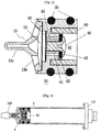
- FIG. 1 is an exploded perspective view illustrating a syringe piston used in fat transplantation according to a first preferred embodiment of the present invention
- FIG. 2 is a sectional view of an assembly of the syringe piston according to the first preferred embodiment of the present invention
- FIG. 3 is a sectional view illustrating the syringe piston according to the first preferred embodiment of the present invention coupled with a vessel;
- FIG. 4 is an exploded sectional view of main parts of the syringe piston according to the first preferred embodiment of the present invention
- FIG. 5 is a view illustrating suction, separation, and transplantation of fat according to the preferred embodiment of the present invention.
- FIG. 6 is a view illustrating examples, in which fats are suctioned by the syringe piston according to the preferred embodiment of the present invention and a conventional syringe piston and density gradient centrifugation is performed;
- FIG. 7 is an exploded perspective view illustrating a syringe piston used in fat transplantation according to a second preferred embodiment of the present invention.
- FIG. 8 is a sectional view of an assembly of the syringe piston according to the second preferred embodiment of the present invention.
- FIGS. 9 to 11 are views illustrating operation of the syringe piston according to the second preferred embodiment of the present invention.
- FIG. 12 is an exploded perspective view illustrating a syringe piston used in fat transplantation according to a third preferred embodiment of the present invention.
- FIG. 13 is a sectional view of an assembly of the syringe piston according to the third preferred embodiment of the present invention.
- FIGS. 14 to 16 are views illustrating operation of the syringe piston according to the third preferred embodiment of the present invention.
- FIG. 17 is an exploded perspective view illustrating a syringe piston used in fat transplantation according to a fourth preferred embodiment of the present invention.
- FIG. 18 is a sectional view of an assembly of the syringe piston according to the fourth preferred embodiment of the present invention.
- FIGS. 19 to 21 are views illustrating operation of the syringe piston according to the fourth preferred embodiment of the present invention.
- FIG. 1 is an exploded perspective view illustrating a syringe piston used in fat transplantation according to a first preferred embodiment of the present invention
- FIG. 2 is a sectional view of an assembly of the syringe piston according to the first preferred embodiment of the present invention
- FIG. 3 is a sectional view illustrating the syringe piston according to the first preferred embodiment of the present invention coupled with a vessel.
- the syringe piston a used in fat transplantation includes a piston body 10 without a shaft, a packing 20 coupled with the outer surface of the piston body 10 to form a seal between a cylindrical vessel b and the piston body 10 , a free oil discharging hole 30 for communicating the front side with the rear side of the piston body 10 , an opening and closing device 40 for opening and closing the free oil discharging hole 30 , a filtering device formed in a free oil discharging passage, and a weight 60 coupled with the rear side of the piston body 10 . All the elements of the syringe piston according to the first preferred embodiment of the present invention are made of non-toxic materials.
- the cylindrical vessel b is structured such that suction of fat and the transplantation of fat are performed in the cylindrical vessel in the state of preventing the fat from contacting air.
- the cylindrical vessel b has a syringe shape and a rear cap 110 coupled with the rear side of the cylindrical vessel b to close the rear side of the cylindrical vessel b.
- the rear cap 110 is connected to an external pneumatic unit.
- the cylindrical vessel b has also a cannular 100 attached to the front side of the cylindrical vessel b and inserted into the patient to suck and inject fat.
- a front cap 130 is attached to the front side of the cylindrical vessel b to close the cannular 100 so as to prevent substances contained in the cylindrical vessel b from leaking.
- the piston body 10 of the syringe piston moves forward and rearward to suck and discharge fat while closely contacting the inner wall of the cylindrical vessel b and has no a shaft.
- the piston body 10 has a cylindrical shape and is made of synthetic resin to have two ring grooves 11 formed in the outer circumference with which the packings 20 are coupled.
- the packings 20 are conventional packings such as a rubber ring, a silicon ring.
- the ring-shaped packings 20 are inserted into the grooves 11 formed in the piston body 10 so as to form a seal between the syringe piston a and the cylindrical vessel b.
- the filtering device includes a circular net type filter 50 having holes of the size for filtering adipose cells and passing the free oil.
- the filter 50 passes the free oil and filters adipose cells when the density gradient centrifugation is performed so that pure fat can be obtained.
- the filter 50 passes only free oil to the rear side of the cylindrical vessel b when the red blood and the free oil form layers in the cylindrical vessel b so that the free oil is separated from the fat.
- the size of the holes of the filter 50 is about 10 ⁇ m to 100 ⁇ m. Since the free oil infiltrates and passes through the filter 50 due to the difference of specific gravities during the density gradient centrifugation, the filter 50 may comprise a thick filter or several layers of filters having large holes of about 100 ⁇ m, or by a single layer or a few layers of net filters having small holes of about 50 ⁇ m.
- the piston body 10 has a filter groove 12 , formed in the front end of the piston body 10 , into which the filter 50 is inserted. Threads are formed in the inner circumference of the filter groove 12 and a cap 13 is coupled with the threads.
- the cap 13 has a disc shape and is coupled with the filter groove 12 by a thread 13 a formed in the outer circumference of the cap 13 .
- the cap 13 has a plurality of through-holes 13 b through which the sucked fat passes, and a protrusion 13 c , corresponding to the shape of the front end of the cylindrical vessel b, formed in the front side thereof.
- the size of the through-holes 13 b is sufficient to prevent fat tissues from damage when the fat passes the through-holes 13 b.
- the filter can be conveniently replaced with a filter required by a user or an orderer when manufacturing or using the syringe piston a.
- the protrusion 13 c formed in the front end prevents gaps such that the front end of the syringe piston a is engaged with the front end of the cylindrical vessel b when the syringe piston a is coupled with the cylindrical vessel b.
- the protrusion 13 c prevents highly compressible air from remaining in the cylindrical vessel b so that suction efficiency is increased.
- the protrusion 13 c pushes the fat in the cylindrical vessel b to the end so that loss of the fat can be minimized.
- the free oil discharging hole 30 is a passage through which the free oil passing through the filter 50 is separated from adipose cells and moves to the rear side of the syringe piston a in the cylindrical vessel b.
- the free oil discharging hole 30 includes four holes penetrating the filter groove 12 formed in the front end of the piston body 10 and the rear side of the piston body 10 .
- the opening and closing device 40 for opening and closing the free oil discharging hole 30 closes the free oil discharging hole 30 when suctioning fat from the patient or injecting the suctioned fat in the cylindrical vessel b into the patient so that the negative or positive pressure is applied to the syringe piston a from the external pneumatic unit, and opens the free oil discharging hole 30 when the density gradient centrifugation is performed so that the free oil passed through the filter 50 is discharged to the rear side of the cylindrical vessel b.
- the opening and closing device 40 for opening and closing the free oil discharging hole 30 may be structured such that, when the cylindrical vessel b is filled with bodily fluids, the free oil discharging hole 30 is safely opened and closed by external manipulation without risk of contamination.
- the opening and closing device 40 of the first preferred embodiment of the present invention includes a screw hole 41 formed in the central portion of the piston body 10 , the free oil discharging hole 30 formed around the screw hole 41 , a packing groove 42 formed in the rear side of the piston body 10 and covering the free oil discharging hole 30 such that an annular packing 43 is hung on a closing screw 44 and the closing screw 44 is fastened into the screw hole 41 so that the free oil discharging hole 30 can be opened and closed.
- the free oil discharging hole 30 and the opening and closing device 40 prevent pressure from leaking by fastening the closing screw 44 to the end when suctioning and injecting fat, and allow the free oil perfectly escapes a space between the free oil discharging hole 30 and the packing 43 by slightly releasing the closing screw 44 .
- a long screwdriver is used.
- the closing screw 44 is fastened or released so that the free oil discharging hole 30 is easily opened and closed in the state that the cylindrical vessel b is filled with fat.
- the weight 60 presses fat when the density gradient centrifugation is performed so that the separation of the free oil is enhanced.
- the weight 60 may be structured such that the syringe piston a is made of heavy material and serves as the weight, and as shown in FIG. 4 , an annular groove 61 is formed in the circumference of the packing groove 42 into which the packing 43 of the rear side of the syringe piston a is inserted and a ring-shaped weight 60 is coupled with the annular groove 61 .
- the syringe piston a moves smoothly forward due to the weight 60 to press fat, thereby smoothly discharging the free oil.
- the cannular 100 is coupled with the front end of the cylindrical vessel b and the syringe piston a is positioned in the cylindrical vessel b while closing the closing screw 44 to perfectly close the free oil discharging hole 30 .
- the rear side of the cylindrical vessel b is closed by the rear cap 110 and the rear cap 110 is connected to the external pneumatic unit 120 so as to push the syringe piston a to the front end of the cylindrical vessel b using positive pressure.
- the cannular 100 is inserted into the patient and negative pressure is applied to the rear space of the syringe piston a such that the fat extracted from the patient is accommodated in the front space of the syringe piston a (See FIG. 5 a ).
- the front cap 130 is attached to the front end of the cylindrical vessel b instead of the cannular 100 (See FIG. 3 ), the rear cap 110 is detached, and the closing screw 44 is released to open the free oil discharging hole 30 .
- the cylindrical vessel b is inserted into a centrifugal separator 140 and the density gradient centrifugation is performed, mixture of blood and bodily fluids and fat components are separated in turn due to specific gravity difference.
- the fat components occupy the upper layer of the cylindrical vessel b, adipose cells in the fat components are filtered by the filter 50 of the syringe piston a, and the free oil passes through the filter 50 and is naturally discharged through the rear side of the syringe piston a.
- the weight 60 is additionally coupled with the syringe piston a, the weight 60 moves the syringe piston a forward to press the fat, thereby discharging the free oil.
- the cylindrical vessel b is turned upside down to completely remove the free oil, the closing screw 44 is fastened to close the free oil discharging hole 30 , and the rear cap 110 is re-coupled with the rear side of the syringe piston a.
- the front cap 130 of the front end of the cylindrical vessel b is removed, the external pneumatic unit 120 is connected to the rear cap 110 to gradually apply positive pressure to the rear side of the syringe piston a so that blood and bodily fluids are extracted and discharged and only the pure fat remains in the front space of the syringe piston a ( FIG. 5 b ).
- the centrifugal separator 140 is a centrifugal separator having a swing-out type rotor in which the cylindrical vessel b is arranged upright when the swing-out rotor is stopped and is horizontally arranged when the swing-out rotor is rotated.
- the cannular 100 coupled with the front end of the cylindrical vessel b, is inserted into a desired portion of the patient and the pure fat is injected into the patient by applying positive pressure to the rear space of the syringe piston a or transferring the pure fat to other type syringe and using the other type syringe.
- FIG. 6 is a photograph for comparison of an example of the density gradient centrifugation using the syringe piston a according to the present invention and an example of the density gradient centrifugation using a conventional syringe piston, respectively applied to a syringe-shaped vessel having a capacity of 60 cc.
- the photograph on the left, labeled ⁇ net type piston> indicates the result of using the syringe piston according to the present invention
- the photograph on the right, labeled ⁇ conventional piston> indicates the result of using the conventional syringe piston.
- the syringe piston according to the present invention is structured such that a syringe piston (about 8.5 g including a net filter), in which a single net filter, made of stainless steel (SUS 304) and having holes of 60 ⁇ m diameter, is inserted into the filter groove, four free oil discharging holes of 2 mm diameter are formed around the screw hole, and a ring-shaped weight (about 13 g) is attached to the syringe piston, thereby total weight is 21.5 g.
- the conventional syringe piston has no hole through which the free oil passes and a shaft is removed.
- the above examples show result that same quantity of fat is extracted from the patient using pneumatic pressure and the density gradient centrifugation is performed at 5000 rpm.
- red blood is positioned in the lowest layer in the vessel and a mixture layer of free oil and fat is formed in the highest layer in the vessel.
- the syringe piston is positioned between the free oil layer and the fat layer so that the fat layer is clearly distinguished from the free oil layer.
- the result may be caused by the facts that adipose cells and free oil of low specific gravities are separated from the red blood layer and are pushed to the rotation center of the centrifugal separator such that adipose cells are filtered and restricted and the free oil naturally passes through the filter and moves to the outer side of the syringe piston, whereby adipose cells and the free oil are separated from fat, simultaneously, the syringe piston moves forward due to the centrifugal force to press adipose cells and push free oil remained in the adipose cells rearward so that the free oil is separated from fat.
- the weight moves the syringe piston forward so that fat is further pressed and free oil more easily separated.
- FIGS. 7 and 8 are views illustrating a syringe piston used in fat transplantation according to a second preferred embodiment of the present invention
- FIGS. 9 to 11 are views illustrating operation of the syringe piston according to the second preferred embodiment of the present invention.
- the syringe piston according to the second preferred embodiment of the present invention is different from the syringe piston according to the first preferred embodiment of the present invention in view of a free oil discharging hole 300 for communicating the front side and the rear side of a piston body 10 A and an opening and closing device 400 for opening and closing the free oil discharging hole 300 and their operation. Therefore, like numerals are assigned to like elements and the description for structure and operation will be omitted.
- the free oil discharging hole 300 includes a single central hole penetrating the front end and the rear end of the piston body 10 A.
- the opening and closing device 400 for opening and closing the free oil discharging hole 300 includes first and second thin plate check valves 401 and 402 disposed at the sides of the free oil discharging hole 300 and operated to open and close the free oil discharging hole 300 by the external force, first and second fixing covers 403 and 404 respectively having through-holes formed in the centers thereof and fixing the first and second check valves 401 and 402 in the piston body 10 A.
- the first and second check valves 401 and 402 include rims 401 a and 402 a fixed to the piston body 10 A by the fixing covers 403 and 404 , and opening and closing parts 401 b and 402 b , having a size sufficient to open and close the free oil discharging hole 300 , in which the rims 401 a and 402 a are connected to parts of the opening and closing parts 401 b and 402 b by connectors 401 c and 402 c .
- the opening and closing parts 401 b and 402 b are supported by the connectors 401 c and 402 c and are easily deformed by the external force so that the free oil discharging hole 300 is easily opened and closed.
- the syringe piston according to the second preferred embodiment of the present invention can perform the suction of fat, the separation of the pure fat, and the fat transplantation.
- the suction of fat as shown in FIG. 9 , when negative pressure is formed in the rear space of the syringe piston a, the opening and closing part 402 b of the second check valve 402 disposed at the rear side is spaced apart from the free oil discharging hole 300 and is opened due to the negative pressure.
- the negative pressure is formed in the rear space as shown in FIG.
- the opening and closing part 402 b of the second check valve 402 is spaced apart from the free oil discharging hole 300 and is opened.
- the opening and closing part 401 b of the check valve 401 disposed at the front side, further closely contacts the free oil discharging hole 300 due to the negative pressure formed in the rear space and closes the free oil discharging hole 300 .
- the syringe piston a moves to the rear space of the cylindrical vessel b so that fat sucked from the patient is accommodated in the front space of the syringe piston a.
- the separation of pure fat using the centrifugal separator 140 (See FIG. 5 b ) after completion of the suction of fat, as shown in FIG. 10 , is performed such that the opening and closing part 401 b of the first check valve 401 , disposed at the front side, is deformed in the direction where the centrifugal force is applied due to the centrifugal force of the centrifugal separator 140 and is away from the free oil discharging hole 300 and opens the free oil discharging hole 300 .
- the weight 60 presses the syringe piston a due to the centrifugal force such that fat positioned in the front space is pressed so that the free oil enters the free oil discharging hole 300 .
- the opening and closing part 402 b of the second check valve 402 disposed at the rear side, is pushed back and is opened by the free oil entering the free oil discharging hole 300 so that the first and second check valves 401 b and 402 b are opened. Therefore, the free oil can be discharged through the free oil discharging hole 300 to the rear space of the syringe piston a.
- the fat in the cylindrical vessel b Due to the difference of specific gravity, the fat in the cylindrical vessel b is separated to blood+bodily fluids, and pure components in turn, and the fat components occupy the highest layer of the cylindrical vessel b during the density gradient centrifugation.
- Adipose cells among the fat components are filtered by the filter 50 of the syringe piston a and the free oil passes through the filter 50 and is discharged through the free oil discharging hole 300 to the rear side.
- the fat transplantation is performed such that, when the positive pressure is applied to the rear space of the syringe piston a, the second check valve 402 , disposed at the rear side, further closely contacts the free oil discharging hole 300 due to the positive pressure and closes the free oil discharging hole 300 .
- the syringe piston a can be moved to the front side using the positive pressure so that fat can be injected into human body and pure fat is transferred to other type syringe and is injected into the patient.
- the suction of fat, the separation of fat, and the fat transplantation can be performed.
- the first and second check valves 401 and 402 are automatically opened and closed, bothersome operations such as fastening and releasing the closing screw 44 can be omitted so that convenient and rapid operation can be performed.
- FIGS. 12 and 13 are views illustrating a syringe piston used in fat transplantation according to a third preferred embodiment of the present invention
- FIGS. 14 to 16 are views illustrating operation of the syringe piston according to the third preferred embodiment of the present invention.
- the syringe piston of the third preferred embodiment is different from the syringe piston of the second preferred embodiment in that an outer filtering circumference 14 is formed to filter fat by maintaining a gap H (See FIG.
- the suction of fat, the separation of pure fat, and the fat transplantation can be performed.
- the suction of fat as shown in FIG.
- the opening and closing part 402 b of the second check valve 402 disposed at the rear side is spaced apart from the free oil discharging hole 300 and is opened due to the negative pressure, but the opening and closing part 401 b of the check valve 401 , disposed at the front side, further closely contacts the free oil discharging hole 300 due to the negative pressure formed in the rear space and closes the free oil discharging hole 300 .
- the syringe piston a moves to the rear space of the cylindrical vessel b so that fat sucked from the patient is accommodated in the front space of the syringe piston a.
- the separation of pure fat using the centrifugal separator 140 (See FIG. 5 b ) after completion of the suction of fat, as shown in FIG. 15 , is performed such that the opening and closing part 401 b of the first check valve 401 , disposed at the front side, is deformed in the direction where the centrifugal force is applied due to the centrifugal force of the centrifugal separator 140 and is away from the free oil discharging hole 300 and opens the free oil discharging hole 300 .
- the weight 60 presses the syringe piston a due to the centrifugal force such that fat positioned in the front space is pressed so that the free oil enters the free oil discharging hole 300 .
- the opening and closing part 402 b of the second check valve 402 disposed at the rear side, is pushed back and is opened by the free oil entering the free oil discharging hole 300 so that the first and second check valves 401 b and 402 b are opened. Therefore, the free oil can be discharged through the free oil discharging hole 300 to the rear space of the syringe piston a.
- the fat in the cylindrical vessel b is separated into blood+bodily fluids, and pure components in turn, and the fat components occupy the highest layer of the cylindrical vessel b during the density gradient centrifugation.
- Adipose cells among the fat components are filtered by the outer filtering circumference 14 of the piston body 10 B for maintaining the gap 10 ⁇ m to 100 ⁇ m between the piston body 10 B and the inner circumference of the cylindrical vessel b, and the free oil passes through the outer filtering circumference.
- the free oil passed through the outer filtering circumference moves to the free oil discharging hole 300 through the through-holes 300 and passes through the free oil discharging hole 400 so that the free oil is naturally discharged to the rear side the syringe piston a.
- the fat transplantation is performed such that, when the positive pressure is applied to the rear space of the syringe piston a, the second check valve 402 , disposed at the rear side, further closely contacts the free oil discharging hole 300 due to the positive pressure and closes the free oil discharging hole 300 .
- the syringe piston a can be moved to the front side using the positive pressure so that fat can be injected into the patient and pure fat is transferred to other type syringe and injected into the patient.
- the suction of fat, the separation of fat, and the fat transplantation can be performed.
- the first and second check valves 401 and 402 are automatically opened and closed, bothersome operations such as fastening and releasing the closing screw 44 can be omitted so that convenient and rapid operation can be performed.
- the syringe piston of the third preferred embodiment does not use a filter, unlike the syringe piston of the second preferred embodiment, so that the number of parts is reduced, the costs can be reduced, and the parts of the syringe piston of the third preferred embodiment can be easily assembled into the syringe piston of the third preferred embodiment.
- FIGS. 17 and 18 are views illustrating a syringe piston used in fat transplantation according to a fourth preferred embodiment of the present invention
- FIGS. 19 to 21 are views illustrating operation of the syringe piston according to the fourth preferred embodiment of the present invention.
- the syringe piston of the fourth preferred embodiment adopts only the free oil discharging hole 30 of a piston body 10 C and the opening and closing device 40 of the syringe piston of the first preferred embodiment, and all other elements are the same as those of the syringe piston of the third preferred embodiment.
- like numerals are assigned to like elements of the syringe pistons of the first and third preferred embodiments and the description for structure and operation will be omitted.
- the suction of fat, the separation of pure fat, and the fat transplantation can be performed.
- the suction of fat as shown in FIG. 19 , when negative pressure is formed in the rear space of the syringe piston a by fastening the closing screw 44 such that the free oil discharging hole 30 is closed by the packing 43 , the syringe piston a moves to the rear space of the cylindrical vessel b so that fat sucked from the patient is accommodated in the front space of the syringe piston a.
- the separation of pure fat using the centrifugal separator 140 (See FIG. 5 b ) after completion of the suction of fat, as shown in FIG. 20 , is performed such that the closing screw 44 is released to form a gap between the packing 43 and the free oil discharging hole 30 so that the free oil discharging hole 30 is opened.
- the centrifugal separator 140 when the centrifugal separator 140 is operated to generate centrifugal force, the weight 60 presses the syringe piston a to the front side due to the centrifugal force and the fat disposed in the front space is pressed.
- the free oil is discharged through the opened free oil discharging hole 30 from the front space to the rear space.
- the fat in the cylindrical vessel b is separated into blood+bodily fluids, and pure components in turn, and the fat components occupy the highest layer of the cylindrical vessel b after density gradient centrifugation.
- Adipose cells among the fat components are filtered by the outer filtering circumference 14 of the piston body 10 C for maintaining the gap 10 ⁇ m to 100 ⁇ m between the piston body 10 C and the inner circumference of the cylindrical vessel b, and the free oil passes through the outer filtering circumference 14 .
- the free oil having passed through the outer filtering circumference 14 moves to the free oil discharging hole 30 through the through-holes 15 and passes through the free oil discharging hole 30 so that the free oil is naturally discharged to the rear side the syringe piston a.
- the syringe piston a can be moved to the front side so that fat can be injected into the patient and pure fat is transferred to other type syringe and injected into the patient.
- the suction of fat, the separation of fat, and the fat transplantation can be performed.
- the positive or negative pressure is not applied to the rear space of the syringe piston, but a user can directly operate the syringe piston a.
- the syringe piston of the fourth preferred embodiment of the present invention since, according to the syringe piston of the fourth preferred embodiment of the present invention, the filter 50 of the syringe piston in the first and second preferred embodiments and the check valves 401 and 402 of the second and third preferred embodiment are not used, the syringe piston of the fourth preferred embodiment is applicable to a small syringe used in the fat transplantation and can be effectively used in a syringe in which it is difficult to apply the negative or positive pressure to the rear space of the syringe piston.
- the syringe piston of the present invention effectively separates free oil from the sucked fat using the syringe piston having a filtering device, and those skilled in the art will appreciate that various modifications, additions and substitutions are possible, without departing from the scope and spirit of the invention.
- the syringe piston used in fat transplantation according to the present invention is structured such that the free oil is easily separated from the sucked fat by the syringe piston having a filter and is naturally discharged to the rear side of the syringe piston so that the syringe piston of the present invention is conveniently used in the suction of fat, the separation of pure fat, and the fat transplantation.
Landscapes
- Health & Medical Sciences (AREA)
- Animal Behavior & Ethology (AREA)
- Life Sciences & Earth Sciences (AREA)
- Anesthesiology (AREA)
- Biomedical Technology (AREA)
- General Health & Medical Sciences (AREA)
- Hematology (AREA)
- Engineering & Computer Science (AREA)
- Vascular Medicine (AREA)
- Heart & Thoracic Surgery (AREA)
- Public Health (AREA)
- Veterinary Medicine (AREA)
- Materials For Medical Uses (AREA)
- Measurement Of The Respiration, Hearing Ability, Form, And Blood Characteristics Of Living Organisms (AREA)
- Medicines Containing Material From Animals Or Micro-Organisms (AREA)
- External Artificial Organs (AREA)
- Infusion, Injection, And Reservoir Apparatuses (AREA)
Priority Applications (1)
| Application Number | Priority Date | Filing Date | Title |
|---|---|---|---|
| US12/885,918 US8926487B2 (en) | 2004-06-23 | 2010-09-20 | Method of separating free oil from fat |
Applications Claiming Priority (3)
| Application Number | Priority Date | Filing Date | Title |
|---|---|---|---|
| KR1020040047260A KR100553669B1 (ko) | 2004-06-23 | 2004-06-23 | 지방 흡입 이식용 주사기의 피스턴 |
| KR10-2004-0047260 | 2004-06-23 | ||
| PCT/KR2005/001965 WO2006001651A1 (en) | 2004-06-23 | 2005-06-23 | Syringe piston using in fat transplantatio |
Related Parent Applications (1)
| Application Number | Title | Priority Date | Filing Date |
|---|---|---|---|
| PCT/KR2005/001965 A-371-Of-International WO2006001651A1 (en) | 2004-06-23 | 2005-06-23 | Syringe piston using in fat transplantatio |
Related Child Applications (1)
| Application Number | Title | Priority Date | Filing Date |
|---|---|---|---|
| US12/885,918 Continuation US8926487B2 (en) | 2004-06-23 | 2010-09-20 | Method of separating free oil from fat |
Publications (2)
| Publication Number | Publication Date |
|---|---|
| US20080091147A1 US20080091147A1 (en) | 2008-04-17 |
| US7819846B2 true US7819846B2 (en) | 2010-10-26 |
Family
ID=35782027
Family Applications (2)
| Application Number | Title | Priority Date | Filing Date |
|---|---|---|---|
| US10/595,572 Active 2026-07-07 US7819846B2 (en) | 2004-06-23 | 2005-06-23 | Syringe piston using in fat transplantation |
| US12/885,918 Active US8926487B2 (en) | 2004-06-23 | 2010-09-20 | Method of separating free oil from fat |
Family Applications After (1)
| Application Number | Title | Priority Date | Filing Date |
|---|---|---|---|
| US12/885,918 Active US8926487B2 (en) | 2004-06-23 | 2010-09-20 | Method of separating free oil from fat |
Country Status (6)
| Country | Link |
|---|---|
| US (2) | US7819846B2 (zh) |
| EP (1) | EP1758628B1 (zh) |
| JP (1) | JP4435230B2 (zh) |
| KR (1) | KR100553669B1 (zh) |
| CN (1) | CN100534542C (zh) |
| WO (1) | WO2006001651A1 (zh) |
Cited By (3)
| Publication number | Priority date | Publication date | Assignee | Title |
|---|---|---|---|---|
| US20110060361A1 (en) * | 2009-09-08 | 2011-03-10 | Baxter International Inc. | Reconstitution and applicator system for wound sealant product |
| US9427335B2 (en) | 2014-03-18 | 2016-08-30 | Biomet Biologics, LLC. | Method for rinsing and delivering bone graft |
| US20190167871A1 (en) * | 2012-04-12 | 2019-06-06 | Sisu Global Health, Inc. | Blood filtering component, apparatus, and method |
Families Citing this family (47)
| Publication number | Priority date | Publication date | Assignee | Title |
|---|---|---|---|---|
| KR100768903B1 (ko) * | 2000-07-28 | 2007-10-22 | 가부시키가이샤 가네카 | 외관 특성이 뛰어난 아크릴계 섬유 및 파일 포백 |
| US7686825B2 (en) | 2004-03-25 | 2010-03-30 | Hauser David L | Vascular filter device |
| KR100628364B1 (ko) * | 2005-07-07 | 2006-09-27 | 메디칸(주) | 지방 흡입 이식용 주사기의 피스턴 |
| US7713232B2 (en) * | 2005-11-04 | 2010-05-11 | Medrad, Inc. | System for washing and processing of cells for delivery thereof to tissue |
| US20130261606A1 (en) * | 2007-04-30 | 2013-10-03 | Andrew Technologies Llc | Harvesting Fat Tissue Using Tissue Liquefaction |
| US8986185B2 (en) * | 2009-09-24 | 2015-03-24 | Lipovera, Llc | Syringe centrifuge systems |
| KR101137964B1 (ko) | 2009-12-08 | 2012-04-20 | 도병록 | 지방 조직 이식용 주사기 및 이를 갖는 지방 조직 분배 장치 |
| TR201006093A2 (tr) * | 2010-07-23 | 2012-02-21 | Eren Orhan | Aspirasyon kesi biyopsi iğnesi. |
| WO2012061140A1 (en) * | 2010-10-25 | 2012-05-10 | Medrad, Inc. | Bladder syringe fluid delivery system |
| US9498570B2 (en) | 2010-10-25 | 2016-11-22 | Bayer Healthcare Llc | Bladder syringe fluid delivery system |
| US20120142514A1 (en) * | 2010-12-02 | 2012-06-07 | Medikan Co., Ltd. | Syringe for specific gravity distinction and fat tissue components separating method therewith |
| KR101350867B1 (ko) | 2011-01-18 | 2014-01-13 | 양현진 | 비중 구분용 주사기 및 지방 분리 방법 |
| KR101150529B1 (ko) * | 2011-01-18 | 2012-05-31 | 양현진 | 지방 분리용 주사기 및 그 주사기를 이용한 지방 분리 방법 |
| CA2834407A1 (en) * | 2011-04-29 | 2012-11-01 | Andrew Technologies Llc | Harvesting fat tissue using tissue liquefaction |
| US9480464B2 (en) | 2011-07-29 | 2016-11-01 | New York University | Tissue collection system |
| EP2744345A4 (en) * | 2011-08-17 | 2015-03-11 | Harvest Technologies Corp | SEPARATION OF OILS IN THE FRACTIONATION OF SUCKLED FAT |
| KR101869944B1 (ko) | 2011-10-28 | 2018-06-21 | 메디칸 주식회사 | 생체지방 내 불순물 제거를 위한 의료용 불순물 제거기구, 생체지방 내 불순물을 제거하는 방법 및 생체지방 |
| US20150044179A1 (en) | 2012-02-24 | 2015-02-12 | Masanori Saeki | Cell preparation including fat cell |
| US9180252B2 (en) | 2012-04-20 | 2015-11-10 | Bayer Medical Care Inc. | Bellows syringe fluid delivery system |
| KR101178986B1 (ko) | 2012-05-24 | 2012-08-31 | 주식회사 티에이치엠코리아 | 주사기용 안전 필터 및 이를 구비하는 주사기 |
| CN102961805A (zh) * | 2012-06-18 | 2013-03-13 | 韶山市夏龙医疗器械制造有限公司 | 自提纯脂肪定量移植器 |
| JP6362588B2 (ja) * | 2013-05-02 | 2018-07-25 | 正典 佐伯 | 毛髪再生用の細胞製剤 |
| KR101467945B1 (ko) * | 2013-07-11 | 2014-12-03 | 전북대학교산학협력단 | 필터 내장형 주사기 |
| WO2015056997A1 (ko) * | 2013-10-18 | 2015-04-23 | 메디칸(주) | 소립자 물질 정제장치 및 정제방법 |
| WO2015061365A1 (en) | 2013-10-21 | 2015-04-30 | Inceptus Medical, Llc | Methods and apparatus for treating embolism |
| KR102253045B1 (ko) * | 2014-04-18 | 2021-05-18 | 메디칸(주) | 피스톤 |
| DE102015118011A1 (de) * | 2015-10-22 | 2017-04-27 | Human Med Ag | Vorrichtung zur Transplantation von Körperfett |
| CA3241647A1 (en) | 2015-10-23 | 2017-04-27 | Inari Medical, Inc. | Intravascular treatment of vascular occlusion and associated devices, systems, and methods |
| US10774301B2 (en) | 2016-07-11 | 2020-09-15 | Board Of Trustees Of Southern Illinois University | Syringe system for fluid separation |
| CN106860923A (zh) * | 2017-01-24 | 2017-06-20 | 北京欧扬医疗美容门诊部有限公司 | 一种短期维持脂肪细胞活性的多功能自体脂肪移植装置 |
| KR102025496B1 (ko) | 2017-09-05 | 2019-09-25 | 이준석 | 원심분리용 피스톤 및 이를 포함하는 원심분리 장치 |
| CN108065971B (zh) * | 2017-12-28 | 2023-12-15 | 山西阳光中天医疗器械有限公司 | 一种可提供持续负压的脂肪抽吸装置及其使用方法 |
| CN107983011B (zh) * | 2017-12-28 | 2024-03-08 | 山西阳光中天医疗器械有限公司 | 一种用于分离脂肪混合液的滤油装置 |
| US11154314B2 (en) | 2018-01-26 | 2021-10-26 | Inari Medical, Inc. | Single insertion delivery system for treating embolism and associated systems and methods |
| US11229722B2 (en) * | 2018-01-29 | 2022-01-25 | Omer Peled | System and method for harvesting autologous adipose tissue |
| KR102051207B1 (ko) * | 2018-01-30 | 2019-12-03 | 이준석 | 원심분리용 피스톤 |
| CN112135606A (zh) | 2018-07-04 | 2020-12-25 | 佐伯正典 | 干细胞滤液制剂和其制备方法 |
| CN112867455A (zh) | 2018-08-13 | 2021-05-28 | 伊纳里医疗有限公司 | 治疗栓塞的系统和相关的装置和方法 |
| MY195849A (en) * | 2018-09-05 | 2023-02-23 | Kin Mun Chin | Device for Filtering |
| US11964137B2 (en) * | 2019-01-16 | 2024-04-23 | Boston Scientific Scimed, Inc. | Cryotherapeutic delivery device |
| JP2022551992A (ja) | 2019-10-16 | 2022-12-14 | イナリ メディカル, インコーポレイテッド | 血管閉塞を治療するためのシステム、デバイス、及び方法 |
| CN112067492A (zh) * | 2020-07-13 | 2020-12-11 | 内蒙古沙漠之神生物科技有限公司 | 一种骆驼奶成分检测方法 |
| KR102532751B1 (ko) * | 2020-10-15 | 2023-05-16 | 임형규 | 피스톤 |
| CN113457220A (zh) * | 2021-07-29 | 2021-10-01 | 厦门博森再生医学工程有限公司 | 一种活塞组件及分离装置 |
| KR102446918B1 (ko) * | 2021-08-26 | 2022-09-26 | (주)비에스엘레스트 | 원심분리용 피스톤 및 이를 포함하는 원심분리 장치 |
| US20230405610A1 (en) | 2021-11-09 | 2023-12-21 | Jun Seok Lee | Centrifugal piston and centrifugal separation device having same |
| WO2023192925A2 (en) * | 2022-03-31 | 2023-10-05 | Inari Medical, Inc. | Blood-filtering devices for use with clot treatment systems |
Citations (14)
| Publication number | Priority date | Publication date | Assignee | Title |
|---|---|---|---|---|
| US3779383A (en) * | 1972-04-25 | 1973-12-18 | Becton Dickinson Co | Sealed assembly for separation of blood components and method |
| US3799342A (en) * | 1970-07-27 | 1974-03-26 | Medical Res & Dev Inc | Method of using a serum separator |
| US3897337A (en) * | 1974-02-27 | 1975-07-29 | Becton Dickinson Co | Plasma separator assembly having interface-seeking piston with centrifugal valve |
| US3931018A (en) * | 1974-08-09 | 1976-01-06 | Becton, Dickinson And Company | Assembly for collection, separation and filtration of blood |
| US3931010A (en) * | 1974-02-27 | 1976-01-06 | Becton, Dickinson And Company | Serum/plasma separators with centrifugal valves |
| US3954614A (en) * | 1972-07-31 | 1976-05-04 | Glasrock Products, Inc. | Serum skimmer and filter separation unit |
| US3970565A (en) * | 1973-11-27 | 1976-07-20 | Aktiebolaget Stille-Werner | Separating and filtering device |
| US4685472A (en) * | 1984-01-23 | 1987-08-11 | Rudolph Muto | Specimen collector |
| US4753634A (en) | 1986-10-31 | 1988-06-28 | Johnson Gerald W | Fat collection syringe |
| US4800020A (en) * | 1987-05-21 | 1989-01-24 | Xydex Corporation | Piston filtering device |
| US5316445A (en) * | 1993-03-03 | 1994-05-31 | Wagner Spray Tech Corporation | Pumping apparatus with piston seal and cylinder removing means |
| US5549816A (en) * | 1995-10-31 | 1996-08-27 | Hach Company | Re-usable piston filter system |
| JP2002126083A (ja) | 2000-10-27 | 2002-05-08 | Shinji Yoshizawa | 移植用脂肪注入器 |
| KR200327374Y1 (ko) | 2003-07-04 | 2003-09-19 | 이희영 | 지방 흡입 이식 주사기의 피스턴 헤드 |
Family Cites Families (8)
| Publication number | Priority date | Publication date | Assignee | Title |
|---|---|---|---|---|
| US3894952A (en) * | 1974-02-27 | 1975-07-15 | Becton Dickinson Co | Serum/plasma separator assembly having interface-seeking piston |
| US3891553A (en) * | 1974-02-27 | 1975-06-24 | Becton Dickinson Co | Serum and plasma separator {13 {0 constrictionless type |
| US5354483A (en) * | 1992-10-01 | 1994-10-11 | Andronic Technologies, Inc. | Double-ended tube for separating phases of blood |
| US7195606B2 (en) * | 2001-02-26 | 2007-03-27 | Erythrosave Ltd. | Syringe and a method for its utilization in analysis |
| US7195610B1 (en) * | 2001-09-17 | 2007-03-27 | Cardinal Health 303, Inc. | Pneumatic syringe driver |
| WO2003099412A1 (en) * | 2002-05-24 | 2003-12-04 | Biomet Manufacturing Corp. | Apparatus and method for separating and concentrating fluids containing multiple components |
| KR200327274Y1 (ko) * | 2003-06-17 | 2003-09-19 | 주식회사 에코셋 | 로타리식 제진기의 구동,종동 및 이송 스프로켓트 |
| US20050124073A1 (en) * | 2003-12-09 | 2005-06-09 | Entire Interest | Fat collection and preparation system and method |
-
2004
- 2004-06-23 KR KR1020040047260A patent/KR100553669B1/ko active IP Right Review Request
-
2005
- 2005-06-23 WO PCT/KR2005/001965 patent/WO2006001651A1/en not_active Application Discontinuation
- 2005-06-23 EP EP05765828.8A patent/EP1758628B1/en not_active Not-in-force
- 2005-06-23 JP JP2007509403A patent/JP4435230B2/ja active Active
- 2005-06-23 US US10/595,572 patent/US7819846B2/en active Active
- 2005-06-23 CN CNB2005800018409A patent/CN100534542C/zh active Active
-
2010
- 2010-09-20 US US12/885,918 patent/US8926487B2/en active Active
Patent Citations (14)
| Publication number | Priority date | Publication date | Assignee | Title |
|---|---|---|---|---|
| US3799342A (en) * | 1970-07-27 | 1974-03-26 | Medical Res & Dev Inc | Method of using a serum separator |
| US3779383A (en) * | 1972-04-25 | 1973-12-18 | Becton Dickinson Co | Sealed assembly for separation of blood components and method |
| US3954614A (en) * | 1972-07-31 | 1976-05-04 | Glasrock Products, Inc. | Serum skimmer and filter separation unit |
| US3970565A (en) * | 1973-11-27 | 1976-07-20 | Aktiebolaget Stille-Werner | Separating and filtering device |
| US3897337A (en) * | 1974-02-27 | 1975-07-29 | Becton Dickinson Co | Plasma separator assembly having interface-seeking piston with centrifugal valve |
| US3931010A (en) * | 1974-02-27 | 1976-01-06 | Becton, Dickinson And Company | Serum/plasma separators with centrifugal valves |
| US3931018A (en) * | 1974-08-09 | 1976-01-06 | Becton, Dickinson And Company | Assembly for collection, separation and filtration of blood |
| US4685472A (en) * | 1984-01-23 | 1987-08-11 | Rudolph Muto | Specimen collector |
| US4753634A (en) | 1986-10-31 | 1988-06-28 | Johnson Gerald W | Fat collection syringe |
| US4800020A (en) * | 1987-05-21 | 1989-01-24 | Xydex Corporation | Piston filtering device |
| US5316445A (en) * | 1993-03-03 | 1994-05-31 | Wagner Spray Tech Corporation | Pumping apparatus with piston seal and cylinder removing means |
| US5549816A (en) * | 1995-10-31 | 1996-08-27 | Hach Company | Re-usable piston filter system |
| JP2002126083A (ja) | 2000-10-27 | 2002-05-08 | Shinji Yoshizawa | 移植用脂肪注入器 |
| KR200327374Y1 (ko) | 2003-07-04 | 2003-09-19 | 이희영 | 지방 흡입 이식 주사기의 피스턴 헤드 |
Non-Patent Citations (1)
| Title |
|---|
| English translation of applicant submitted foreign reference: Application No. 20-2003-0021484. * |
Cited By (5)
| Publication number | Priority date | Publication date | Assignee | Title |
|---|---|---|---|---|
| US20110060361A1 (en) * | 2009-09-08 | 2011-03-10 | Baxter International Inc. | Reconstitution and applicator system for wound sealant product |
| US9220486B2 (en) | 2009-09-08 | 2015-12-29 | Baxter International Inc. | Reconstitution and applicator system for wound sealant product |
| US20190167871A1 (en) * | 2012-04-12 | 2019-06-06 | Sisu Global Health, Inc. | Blood filtering component, apparatus, and method |
| US10994063B2 (en) * | 2012-04-12 | 2021-05-04 | Sisu Global Health, Inc. | Blood filtering component, apparatus, and method |
| US9427335B2 (en) | 2014-03-18 | 2016-08-30 | Biomet Biologics, LLC. | Method for rinsing and delivering bone graft |
Also Published As
| Publication number | Publication date |
|---|---|
| KR20050122102A (ko) | 2005-12-28 |
| CN1905916A (zh) | 2007-01-31 |
| US20110309037A1 (en) | 2011-12-22 |
| US20080091147A1 (en) | 2008-04-17 |
| CN100534542C (zh) | 2009-09-02 |
| EP1758628A4 (en) | 2010-07-14 |
| JP2007533396A (ja) | 2007-11-22 |
| US8926487B2 (en) | 2015-01-06 |
| WO2006001651A1 (en) | 2006-01-05 |
| EP1758628A1 (en) | 2007-03-07 |
| EP1758628B1 (en) | 2016-10-26 |
| JP4435230B2 (ja) | 2010-03-17 |
| KR100553669B1 (ko) | 2006-02-24 |
Similar Documents
| Publication | Publication Date | Title |
|---|---|---|
| US7819846B2 (en) | Syringe piston using in fat transplantation | |
| KR100628364B1 (ko) | 지방 흡입 이식용 주사기의 피스턴 | |
| JP5824160B2 (ja) | 成分分離器 | |
| EP2801610B1 (en) | Cell separation container | |
| US20080057597A1 (en) | Fat collection and preparation system and method | |
| KR101982766B1 (ko) | 지방줄기세포 분리장치 | |
| CN201492455U (zh) | 用于脂肪抽取、分离和移植的装置 | |
| KR20140075540A (ko) | 지방채취용기 | |
| US11980709B2 (en) | System and related methods for fat harvesting | |
| CN108065971A (zh) | 一种可提供持续负压的脂肪抽吸装置及其使用方法 | |
| KR101350867B1 (ko) | 비중 구분용 주사기 및 지방 분리 방법 | |
| KR101150529B1 (ko) | 지방 분리용 주사기 및 그 주사기를 이용한 지방 분리 방법 | |
| KR20130088113A (ko) | 비중 구분용 주사기 및 지방 분리 방법 | |
| CN212143677U (zh) | 用于离心法清洗脂肪的装置 | |
| JP2017164020A (ja) | ピストン、脂肪細胞採取用器具、及び脂肪細胞の採取方法 | |
| KR20190019001A (ko) | 지방분리용 장치 및 지방분리용 장치를 이용한 지방세포 분리 방법 | |
| CN220194130U (zh) | 一种脂肪纯化用抽滤装置 | |
| KR101869944B1 (ko) | 생체지방 내 불순물 제거를 위한 의료용 불순물 제거기구, 생체지방 내 불순물을 제거하는 방법 및 생체지방 | |
| US20220390333A1 (en) | Adipose tissue particle processing, transfer and storage system | |
| KR20140075539A (ko) | 지방흡입장치 | |
| KR20230023274A (ko) | 혈소판 풍부 혈장 추출장치 및 이를 이용한 혈소판 풍부 혈장 추출방법 | |
| CN113440927A (zh) | 乳糜化脂肪水溶性成分提取装置与方法 | |
| WO2021059000A2 (en) | A system and set for conversion of adipose cells extracted from the body to adipose cells for re-injecting to the body | |
| KR20230132141A (ko) | 혈액 분리키트 조립체 및 이를 이용한 prp 추출방법 | |
| KR20140075537A (ko) | 지방흡입용 캐뉼라 |
Legal Events
| Date | Code | Title | Description |
|---|---|---|---|
| STCF | Information on status: patent grant |
Free format text: PATENTED CASE |
|
| FPAY | Fee payment |
Year of fee payment: 4 |
|
| SULP | Surcharge for late payment | ||
| MAFP | Maintenance fee payment |
Free format text: PAYMENT OF MAINTENANCE FEE, 8TH YR, SMALL ENTITY (ORIGINAL EVENT CODE: M2552) Year of fee payment: 8 |
|
| MAFP | Maintenance fee payment |
Free format text: PAYMENT OF MAINTENANCE FEE, 12TH YR, SMALL ENTITY (ORIGINAL EVENT CODE: M2553); ENTITY STATUS OF PATENT OWNER: SMALL ENTITY Year of fee payment: 12 |