US7805841B2 - Modular power tool - Google Patents
Modular power tool Download PDFInfo
- Publication number
- US7805841B2 US7805841B2 US11/122,311 US12231105A US7805841B2 US 7805841 B2 US7805841 B2 US 7805841B2 US 12231105 A US12231105 A US 12231105A US 7805841 B2 US7805841 B2 US 7805841B2
- Authority
- US
- United States
- Prior art keywords
- power tool
- handle
- modular power
- drive system
- housing
- Prior art date
- Legal status (The legal status is an assumption and is not a legal conclusion. Google has not performed a legal analysis and makes no representation as to the accuracy of the status listed.)
- Expired - Fee Related, expires
Links
Images


Classifications
-
- B—PERFORMING OPERATIONS; TRANSPORTING
- B27—WORKING OR PRESERVING WOOD OR SIMILAR MATERIAL; NAILING OR STAPLING MACHINES IN GENERAL
- B27B—SAWS FOR WOOD OR SIMILAR MATERIAL; COMPONENTS OR ACCESSORIES THEREFOR
- B27B9/00—Portable power-driven circular saws for manual operation
-
- Y—GENERAL TAGGING OF NEW TECHNOLOGICAL DEVELOPMENTS; GENERAL TAGGING OF CROSS-SECTIONAL TECHNOLOGIES SPANNING OVER SEVERAL SECTIONS OF THE IPC; TECHNICAL SUBJECTS COVERED BY FORMER USPC CROSS-REFERENCE ART COLLECTIONS [XRACs] AND DIGESTS
- Y10—TECHNICAL SUBJECTS COVERED BY FORMER USPC
- Y10T—TECHNICAL SUBJECTS COVERED BY FORMER US CLASSIFICATION
- Y10T83/00—Cutting
- Y10T83/04—Processes
-
- Y—GENERAL TAGGING OF NEW TECHNOLOGICAL DEVELOPMENTS; GENERAL TAGGING OF CROSS-SECTIONAL TECHNOLOGIES SPANNING OVER SEVERAL SECTIONS OF THE IPC; TECHNICAL SUBJECTS COVERED BY FORMER USPC CROSS-REFERENCE ART COLLECTIONS [XRACs] AND DIGESTS
- Y10—TECHNICAL SUBJECTS COVERED BY FORMER USPC
- Y10T—TECHNICAL SUBJECTS COVERED BY FORMER US CLASSIFICATION
- Y10T83/00—Cutting
- Y10T83/95—Machine frame
- Y10T83/96—Guard
Definitions
- the present invention relates generally to a modular power tool.
- the present invention relates to a modular circular saw wherein the handle supports the drive assembly and is adaptable to be fastened on either side of the saw blade, providing a right hand and left hand assembly.
- Circular saws are known in the art. A growth in circular saw applications has created many derivative circular saw designs for each specific type of use. Many of these applications require changes to motor platforms, blade guarding and gear cases. Specifically, most circular saw designs do not allow different motor sizes to fit the same housing. This requires a housing redesign and a new transmission for each different or new motor size. The transmission or gear case is typically the most complex component to develop and dimensionally qualify because it has the most stringent tolerances and becomes the foundation for all the other structure that is mounted to it. Hence, the product development time for a derivative circular saw is extensive and somewhat prohibitive.
- the present invention provides a modular power tool for a circular saw application.
- the modular power tool incorporates a modular drive system that employs a mounting flange portion with a common hole pattern for coupling motors of various sizes to a universal gear case.
- the handle set of the modular power tool is designed with a cavity through which the drive system passes.
- the handle set further includes a universal mating portion for receipt of a variety of battery and power sources.
- the handle set is also reversible for use with both a left hand and right hand configuration.
- the modular drive system and handle set of the modular power tool of this invention reduces the need for derivative circular saw designs by introducing common components.
- FIG. 1 is an exploded perspective view of a modular power tool in a left hand orientation according to the principles of the present invention
- FIG. 2 is an exploded view of the modular power tool in a right hand orientation
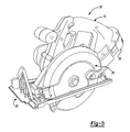
- FIG. 3 is a side view of a handle set according to the principles of the present invention.
- FIG. 4 is a front view of a gear case according to the principles of the present invention.
- FIG. 5 is a perspective view of the modular circular saw in a left hand configuration
- FIG. 6 is a perspective view of the right hand configuration of the modular circular saw according to the principles of the present invention.
- FIGS. 1 and 2 an exploded view of a first embodiment of a modular power tool 10 is shown.
- the present invention is directed towards a circular saw, however, it is to be understood that the principles embodied herein are equally applicable to other types of power tools as well.
- the modular power tool or power circular saw 10 includes a reversible clam shell handle set 12 with a symmetrical motor housing 14 .
- a universal drive train platform is provided with a motor case 18 which has a flange 20 and mounting hole pattern which is designed for the largest motor, such that smaller motors can be provided with the same flange and hole pattern.
- the universal drive train platform also includes a universal gear case 22 .
- Various guards 24 and shoe assemblies 26 can be provided for a specific saw application such as right and left hand blade applications, wood or metal cutting, etc.
- Fasteners 28 extend through mounting holes 30 , provided in the symmetrical motor housing 14 , holes 32 , provided in the reversible clam shell handle set 12 , holes 34 , provided in the flange 20 of the motor case 18 , mounting holes 36 , provided in the universal gear case 22 and finally into mounting holes 38 provided in guard 24 .
- the symmetrical motor housing 14 can be made out of one or two pieces.
- the symmetrical motor housing 14 is generally made from plastic and encloses an end of the motor case 18 .
- Different size symmetrical motor housings 14 can be optionally used to reduce the size of the assembly for different motor sizes. This reduces the cost and development time required of an entire new housing tool.
- the symmetrical motor housing 14 is coupled to the two-piece clam shell handle set 12 .
- the two-piece clam shell handle set 12 incorporates an identical and symmetrical mounting pattern on both sides of each clam shell portion 12 a , 12 b .
- This clam shell handle set 12 has an opening 40 that allows the entire range of desired motor cases 18 to pass through it for mounting onto the universal gear case 22 .
- the clam shell handle set 12 also supports the motor case 18 for coupling to the symmetrical motor housing 14 .
- clam shell handle set 12 has an open end cavity 42 (best shown in FIG. 2 ) designed so that different mold inserts can be used for different battery and power sources to be connected to the power circular saw 10 .
- Clam shell handle set 12 further includes a trigger 44 and a safety 46 (best shown in FIG. 3 ). Both trigger 44 and safety 46 are generally made from plastic. Safety 46 extends through the clam shell handle set 12 , and must be held for the trigger 44 to release.
- the modular universal transmission and gear case 22 is symmetrical and has the ability to incorporate numerous gear ratios, motor platforms and guard designs.
- the universal gear case 22 has symmetrical air flow vents 39 with fins and ribbing 48 that can direct air to remove dust and debris from a cutting line in both right and left handed blade applications.
- the assembly of power circular saw 10 generally involves inserting motor case 18 through the cavity 40 of the clam shell handle set 12 .
- the motor case 18 has a flange 20 with holes 34 which couple the universal gear case 22 to the motor case 18 .
- the universal gear case 22 is further coupled to the guard and shoe assembly 24 , 26 .
- Symmetrical motor housing 14 is fixed to the end of the clam shell handle set 12 such that it covers the rest of the motor case 18 .
- the symmetrical motor housing 14 provides the starting point for the fasteners 28 , specifically fasteners 28 are threaded though the symmetrical motor housing 14 via holes 30 into the clam shell handle set 12 via holes 32 , through motor assembly holes 34 , the gear case holes 36 and into the guard 24 .
- the battery 50 ( FIGS. 5 and 6 ) or other power source are mounted onto cavity 42 .
- the left hand assembly for the power circular saw 10 is shown FIG. 5 .
- the right hand assembly for the power circular saw 10 is shown in FIG. 6 and is achieved by reversing the orientation of the clam shell handle set 12 .
- the design of the present invention allows the clam shell handle set 12 to be mounted either to the left or to the right of the blade and gear case.
- Features that allow this arrangement include the identical and symmetrical mounting fasteners on both sides of each handle clam shell.
- the handle set defines an opening that is large enough for the entire range of different sized motor assemblies to pass through it.
- the motor housing and gear case are symmetrically designed for left hand and right hand use. The blade guard and shoe can be changed for different uses and for left or right hand orientations.
Landscapes
- Life Sciences & Earth Sciences (AREA)
- Engineering & Computer Science (AREA)
- Mechanical Engineering (AREA)
- Wood Science & Technology (AREA)
- Forests & Forestry (AREA)
- Sawing (AREA)
- Portable Power Tools In General (AREA)
- Portable Nailing Machines And Staplers (AREA)
- Surgical Instruments (AREA)
- Manufacturing Of Electrical Connectors (AREA)
Abstract
Description
Claims (23)
Priority Applications (1)
| Application Number | Priority Date | Filing Date | Title |
|---|---|---|---|
| US11/122,311 US7805841B2 (en) | 2002-06-07 | 2005-05-04 | Modular power tool |
Applications Claiming Priority (2)
| Application Number | Priority Date | Filing Date | Title |
|---|---|---|---|
| US10/165,167 US6898854B2 (en) | 2002-06-07 | 2002-06-07 | Modular power tool |
| US11/122,311 US7805841B2 (en) | 2002-06-07 | 2005-05-04 | Modular power tool |
Related Parent Applications (1)
| Application Number | Title | Priority Date | Filing Date |
|---|---|---|---|
| US10/165,167 Division US6898854B2 (en) | 2002-06-07 | 2002-06-07 | Modular power tool |
Publications (2)
| Publication Number | Publication Date |
|---|---|
| US20050198831A1 US20050198831A1 (en) | 2005-09-15 |
| US7805841B2 true US7805841B2 (en) | 2010-10-05 |
Family
ID=29710377
Family Applications (4)
| Application Number | Title | Priority Date | Filing Date |
|---|---|---|---|
| US10/165,167 Expired - Lifetime US6898854B2 (en) | 2002-06-07 | 2002-06-07 | Modular power tool |
| US10/517,034 Expired - Fee Related US7363841B2 (en) | 2002-06-07 | 2003-06-05 | Modular power tool |
| US11/122,311 Expired - Fee Related US7805841B2 (en) | 2002-06-07 | 2005-05-04 | Modular power tool |
| US12/044,280 Expired - Fee Related US7814663B2 (en) | 2002-06-07 | 2008-03-07 | Modular power tool |
Family Applications Before (2)
| Application Number | Title | Priority Date | Filing Date |
|---|---|---|---|
| US10/165,167 Expired - Lifetime US6898854B2 (en) | 2002-06-07 | 2002-06-07 | Modular power tool |
| US10/517,034 Expired - Fee Related US7363841B2 (en) | 2002-06-07 | 2003-06-05 | Modular power tool |
Family Applications After (1)
| Application Number | Title | Priority Date | Filing Date |
|---|---|---|---|
| US12/044,280 Expired - Fee Related US7814663B2 (en) | 2002-06-07 | 2008-03-07 | Modular power tool |
Country Status (11)
| Country | Link |
|---|---|
| US (4) | US6898854B2 (en) |
| EP (1) | EP1511591B1 (en) |
| JP (1) | JP2005532178A (en) |
| CN (1) | CN100522436C (en) |
| AT (1) | ATE526102T1 (en) |
| AU (1) | AU2003243401B8 (en) |
| BR (1) | BR0311621A (en) |
| CA (1) | CA2487383C (en) |
| MX (1) | MXPA04012190A (en) |
| TW (1) | TWI243728B (en) |
| WO (1) | WO2003103881A1 (en) |
Families Citing this family (17)
| Publication number | Priority date | Publication date | Assignee | Title |
|---|---|---|---|---|
| DE10261743A1 (en) * | 2002-12-30 | 2004-07-22 | Robert Bosch Gmbh | Manual circular saw B27B |
| CA2553395A1 (en) * | 2004-01-16 | 2005-08-11 | Credo Technology Corporation | Bevel quadrant and gearbox louver blower system |
| GB2432334B (en) * | 2005-11-21 | 2010-10-06 | Husqvarna Uk Ltd | Power tool |
| US7310879B1 (en) * | 2006-07-27 | 2007-12-25 | Robert Bosch Gmbh | Cutting attachment having an adjustable foot for rotary hand tools |
| US20080034518A1 (en) * | 2006-08-08 | 2008-02-14 | Lindroth Eric D | Counter clock-wise air buffer and sander |
| JP5148297B2 (en) * | 2008-01-10 | 2013-02-20 | 株式会社マキタ | Marnoco |
| CN201483079U (en) * | 2009-06-01 | 2010-05-26 | 南京德朔实业有限公司 | Direct current circular saw |
| JP5468420B2 (en) * | 2010-03-04 | 2014-04-09 | 株式会社マキタ | Hand-held cutting tool |
| JP2012161899A (en) * | 2011-02-09 | 2012-08-30 | Makita Corp | Cutting tool |
| DE102011077622A1 (en) * | 2011-06-16 | 2012-12-20 | Robert Bosch Gmbh | Machine tool device |
| DE102012216979A1 (en) * | 2012-09-21 | 2014-04-17 | Trumpf Laser Gmbh + Co. Kg | Scanner device for deflecting a laser beam 2-dimensionally |
| JP2014148006A (en) * | 2013-02-01 | 2014-08-21 | Makita Corp | Electric power tool and portable circular saw |
| JP6410036B2 (en) * | 2014-11-28 | 2018-10-24 | 工機ホールディングス株式会社 | Electric power tool and electric tool assembling method |
| US10493543B2 (en) * | 2015-03-12 | 2019-12-03 | Robert Bosch Tool Corporation | Power tool motor with reduced electrical noise |
| WO2016150518A1 (en) | 2015-03-26 | 2016-09-29 | Husqvarna Ab | Visible motor saw head layout |
| US20180290322A1 (en) * | 2017-04-10 | 2018-10-11 | Nanjing Chervon Industry Co., Ltd. | Hand-held cutting tool |
| CN108687399A (en) * | 2017-04-10 | 2018-10-23 | 南京德朔实业有限公司 | Hand held cutting tool |
Citations (91)
| Publication number | Priority date | Publication date | Assignee | Title |
|---|---|---|---|---|
| US2545659A (en) | 1946-05-01 | 1951-03-20 | Aro Equipment Corp | Adjustable handle for tools |
| US2962062A (en) | 1958-12-08 | 1960-11-29 | Howard W Winkler | Attachment for power saws |
| US2989995A (en) | 1959-06-17 | 1961-06-27 | Singer Mfg Co | Composite air-directing and heatdissipating gear housings |
| US3262472A (en) | 1964-05-08 | 1966-07-26 | Black & Decker Mfg Co | Depth and bevel adjustment means for portable power-driven saw |
| US3456696A (en) | 1966-07-13 | 1969-07-22 | Rockwell Mfg Co | Portable circular saw |
| US3730239A (en) | 1971-12-10 | 1973-05-01 | Skil Corp | Circular saw with improved movable guard construction |
| US3757194A (en) | 1972-07-03 | 1973-09-04 | Black & Decker Mfg Co | Cordless power tool having removable battery pack |
| US3759019A (en) | 1972-09-06 | 1973-09-18 | Black & Decker Mfg Co | Cantilever motor mounting and brush hold-down |
| US3873862A (en) | 1970-05-13 | 1975-03-25 | Murphy Ind Inc G W | Rotary saw |
| US4060940A (en) * | 1976-01-13 | 1977-12-06 | The Black And Decker Manufacturing Company | Adjustable guard construction for cut-off machine |
| US4221051A (en) | 1979-05-30 | 1980-09-09 | The Singer Company | Circular saw with improved base plate adjustment |
| US4224855A (en) | 1979-04-20 | 1980-09-30 | Roches Emile A Des | Power saw guiding apparatus |
| USD262772S (en) | 1980-01-22 | 1982-01-26 | The Singer Company | Portable circular saw |
| US4326370A (en) | 1979-05-31 | 1982-04-27 | The Toro Company | Rotary lawn mower |
| US4355785A (en) | 1981-02-23 | 1982-10-26 | Westinghouse Electric Corp. | Electrically driven sheave |
| JPS57207003A (en) | 1981-06-15 | 1982-12-18 | Matsushita Electric Works Ltd | Motor circular saw machine |
| US4369546A (en) | 1979-12-28 | 1983-01-25 | Zientara Stanley V | Hand held tools and utensils stabilizer bar, adjustable and non-adjustable |
| JPS58222804A (en) | 1982-06-21 | 1983-12-24 | 松下電工株式会社 | Electric tool |
| JPS58222803A (en) | 1982-06-21 | 1983-12-24 | 松下電工株式会社 | Battery type circular saw |
| JPS59167202A (en) | 1983-03-15 | 1984-09-20 | 松下電工株式会社 | Circular saw |
| US4516324A (en) | 1982-11-01 | 1985-05-14 | Black & Decker Inc. | Modular housing system for a circular saw |
| DE3318507C2 (en) | 1982-06-21 | 1985-11-28 | Matsushita Electric Works, Ltd., Kadoma, Osaka | Electric circular saw |
| JPS6153922A (en) | 1984-08-24 | 1986-03-18 | Hitachi Constr Mach Co Ltd | Work safety device for construction machinery |
| JPS6154561A (en) | 1984-08-24 | 1986-03-18 | Fuji Xerox Co Ltd | Japanese word processor |
| JPS6157161A (en) | 1984-08-28 | 1986-03-24 | Nec Corp | Display method of talking trouble |
| US4609053A (en) | 1982-09-22 | 1986-09-02 | Atlas Copco Aktiebolag | Hammer tool |
| DE3429095C2 (en) | 1983-08-13 | 1987-01-08 | Matsushita Electric Works, Ltd., Kadoma, Osaka | Electrically powered circular saw |
| JPS6235362A (en) | 1985-08-08 | 1987-02-16 | Konishiroku Photo Ind Co Ltd | Method for processing photosensitive lithographic printing plate |
| DE3740200A1 (en) | 1987-11-27 | 1989-06-08 | Black & Decker Inc | Portable, motor-driven circular saw |
| US4847513A (en) | 1988-02-26 | 1989-07-11 | Black & Decker Inc. | Power-operated device with a cooling facility |
| US4856394A (en) | 1988-04-14 | 1989-08-15 | Porter-Cable Corporation | Portable circular saw |
| US4870758A (en) | 1987-12-05 | 1989-10-03 | Makita Electric Works, Ltd. | Portable circular saw |
| US4876797A (en) | 1989-01-17 | 1989-10-31 | Alvaro Zapata | Reduced vibration portable gas operated hand saw |
| JPH0245561A (en) | 1988-08-08 | 1990-02-15 | Toshiba Silicone Co Ltd | Transparent silicone compound composition |
| JPH0248232A (en) | 1988-08-08 | 1990-02-19 | Aisin Aw Co Ltd | Transmitter of four-wheel drive vehicle |
| JPH02303776A (en) | 1989-05-17 | 1990-12-17 | Makita Corp | Portable motor-driven tool |
| JPH0338961A (en) | 1989-07-06 | 1991-02-20 | Fujitsu Ltd | Security system for home trade |
| US5006740A (en) | 1990-06-13 | 1991-04-09 | Milwaukee Electric Tool Corporation | Insulated cooling boot for power tool |
| US5023999A (en) | 1990-08-09 | 1991-06-18 | Ryobi Motor Products Corp. | Unitized tool construction |
| DE9115492U1 (en) | 1991-12-13 | 1992-02-20 | Mafell Maschinenfabrik Rudolf Mey GmbH & Co KG, 7238 Oberndorf | Circular saw with a base plate |
| US5090126A (en) | 1990-07-25 | 1992-02-25 | Higgins Toney D | Rotary tool quick acting retention device |
| USD329363S (en) | 1989-10-20 | 1992-09-15 | Hitachi Koki Company, Limited | Portable circular saw |
| US5170851A (en) | 1989-07-15 | 1992-12-15 | Kress-Elektrik Gmbh & Co. | Electric tool |
| JPH054201A (en) | 1991-06-27 | 1993-01-14 | Matsushita Electric Works Ltd | Motor-driven circular saw |
| JPH0531701A (en) | 1991-06-27 | 1993-02-09 | Matsushita Electric Works Ltd | Electromotive circular sawing machine |
| USD335433S (en) | 1991-03-01 | 1993-05-11 | Skil Corporation | Portable circular saw |
| JPH05318403A (en) | 1992-05-26 | 1993-12-03 | Matsushita Electric Works Ltd | Motor-driven circular saw |
| DE9406040U1 (en) | 1994-04-12 | 1994-06-01 | Atlas Copco Elektrowerkzeuge Gmbh, 71364 Winnenden | Hand tool |
| JPH06278101A (en) | 1993-03-26 | 1994-10-04 | Matsushita Electric Works Ltd | Electric circular saw |
| JPH0752067A (en) | 1993-08-13 | 1995-02-28 | Matsushita Electric Works Ltd | Battery type cutting tool |
| JPH0767681A (en) | 1993-09-03 | 1995-03-14 | Kibun Foods Inc | Method for enhancing elicitor activity of saccharide |
| JPH07161340A (en) | 1993-12-13 | 1995-06-23 | Sanyo Electric Co Ltd | Battery pack used for motor-driven tool |
| US5433008A (en) | 1994-01-31 | 1995-07-18 | Porter-Cable Corporation | Circular saw with variable adjustment stops |
| DE4040091C2 (en) | 1989-12-15 | 1995-07-27 | Hitachi Koki Kk | Electric circular saw with an improved base plate tilting mechanism |
| DE4403189A1 (en) | 1994-02-02 | 1995-08-03 | Bosch Gmbh Robert | Circular saw with pendulum protection hood and with a cutting depth adjustment device |
| JPH07232301A (en) | 1994-02-23 | 1995-09-05 | Matsushita Electric Works Ltd | Electric circular saw |
| EP0466294B1 (en) | 1990-07-10 | 1995-10-04 | Emerson Electric Co. | Improved portable circular saw |
| USD363656S (en) | 1994-08-02 | 1995-10-31 | Black & Decker Inc. | Cordless circular saw |
| JPH08281603A (en) | 1995-04-14 | 1996-10-29 | Ryobi Ltd | Portable rotary tool |
| USD375439S (en) | 1994-12-27 | 1996-11-12 | Makita Corporation | Cordless circular saw |
| DE29513330U1 (en) | 1995-08-19 | 1996-12-19 | Robert Bosch Gmbh, 70469 Stuttgart | Circular saw |
| JPH09141603A (en) | 1995-11-27 | 1997-06-03 | Matsushita Electric Works Ltd | Portable circular saw |
| JPH09141602A (en) | 1995-11-27 | 1997-06-03 | Matsushita Electric Works Ltd | Portable cutting tool |
| JPH09164501A (en) | 1995-12-15 | 1997-06-24 | Matsushita Electric Works Ltd | Electric circular saw |
| USD390081S (en) | 1997-01-21 | 1998-02-03 | Black & Decker Inc. | Circular saw |
| JPH1034564A (en) | 1996-07-24 | 1998-02-10 | Kyushu Hitachi Maxell Ltd | Small electrical equipment and battery pack for small electrical equipment |
| DE19635527A1 (en) | 1996-08-20 | 1998-02-26 | Black & Decker Inc | Hand-held circular saw |
| US5856715A (en) | 1996-12-13 | 1999-01-05 | Ryobi North America, Inc. | Portable electrical power tool having a rare earth permanent magnet motor |
| US5881823A (en) | 1995-06-14 | 1999-03-16 | Robert Bosch Gmbh | Hand machine tool with battery operated drive motor, and battery unit for the same |
| US5902080A (en) | 1997-07-11 | 1999-05-11 | Roto Zip Tool Corporation | Spiral cutting tool with detachable battery pack |
| USD411425S (en) | 1998-03-06 | 1999-06-22 | Makita Corporation | Cordless circular saw |
| JPH11170203A (en) | 1997-12-05 | 1999-06-29 | Hitachi Koki Co Ltd | Portable circular saw |
| USD417648S (en) | 1997-07-01 | 1999-12-14 | Porter-Cable Corporation | Power tool rechargeable battery |
| US6007939A (en) | 1997-07-01 | 1999-12-28 | Porter-Cable Corporation | Battery pack for cordless tools |
| JP2000015602A (en) | 1998-06-30 | 2000-01-18 | Matsushita Electric Works Ltd | Motor-driven circular saw |
| DE19938523A1 (en) | 1998-08-14 | 2000-04-20 | Milwaukee Electric Tool Corp | Movable handle for a powered tool |
| JP2000176908A (en) | 1998-12-15 | 2000-06-27 | Matsushita Electric Works Ltd | Dust collecting type motorized circular saw |
| USD427874S (en) | 1999-06-09 | 2000-07-11 | Makita Corporation | Circular saw |
| USD427872S (en) | 1999-01-18 | 2000-07-11 | Black & Decker Inc. | Circular saw |
| USD428318S (en) | 1999-05-12 | 2000-07-18 | S-B Power Tool Corporation | Circular saw |
| USD428319S (en) | 1999-08-11 | 2000-07-18 | S-B Power Tool Company | Circular saw |
| USD429133S (en) | 1999-04-19 | 2000-08-08 | Choon Nang Electrical Appliance MFY. | Electric saw |
| WO2000051772A1 (en) | 1999-02-26 | 2000-09-08 | Hills Industries Limited | Adjustment mechanism for a saw |
| USD432077S (en) | 1999-07-28 | 2000-10-17 | Black & Decker Inc. | Battery pack |
| US6161293A (en) | 1998-08-14 | 2000-12-19 | One World Technologies, Inc. | Battery powered circular saw |
| US6181032B1 (en) | 1999-07-14 | 2001-01-30 | Black & Decker Inc. | Releasably connecting power packs to electrical appliances |
| US6502647B1 (en) * | 2000-10-16 | 2003-01-07 | Douglas C. Krzyzewski | Pneumatic tool assembly |
| US6536120B1 (en) * | 2000-10-27 | 2003-03-25 | Steven J. Langis | Powered circular saw for left or right handed operation |
| JP3503986B2 (en) | 1994-03-31 | 2004-03-08 | 日産自動車株式会社 | Hose clamp |
| USD487686S1 (en) * | 2002-02-12 | 2004-03-23 | Black & Decker Inc. | Drill chuck, side handle, and collar arrangement |
| US6719067B2 (en) * | 2001-12-27 | 2004-04-13 | Taga Corporation | Insert for a plastic power tool housing |
Family Cites Families (12)
| Publication number | Priority date | Publication date | Assignee | Title |
|---|---|---|---|---|
| US4145811A (en) * | 1977-10-31 | 1979-03-27 | Jarvis Products Corporation | Reciprocating saw |
| DE2951333A1 (en) | 1979-12-20 | 1981-07-02 | Packaging Development Mfg.(Proprietary) Ltd., Claremont, Cape Town | Blank for stackable carton - in which bottom flaps create formation to engage with formation on top of lower box in stack |
| US4835410A (en) | 1988-02-26 | 1989-05-30 | Black & Decker Inc. | Dual-mode corded/cordless system for power-operated devices |
| JPH0398801A (en) | 1989-09-04 | 1991-04-24 | Kubota Corp | Apparatus for bagging grain |
| EP0585614A3 (en) | 1992-08-03 | 1994-03-23 | L'air Liquide, Societe Anonyme Pour L'etude Et L'exploitation Des Procedes Georges Claude | Hollow fiber permeator with tubesheet preform |
| JPH06157161A (en) | 1992-11-20 | 1994-06-03 | Asahi Chem Ind Co Ltd | Lightweight concrete forming material |
| JP3425777B2 (en) | 1992-11-25 | 2003-07-14 | 四国化成工業株式会社 | Microorganisms that exhibit the ability to degrade edible fats and oils and their use |
| JP3314436B2 (en) | 1993-02-10 | 2002-08-12 | 株式会社デンソー | Fuel injection device and airtightness inspection method thereof |
| JP2002048232A (en) | 2000-08-02 | 2002-02-15 | Jatco Transtechnology Ltd | Variable speed control device for continuously variable transmission |
| JP4271353B2 (en) | 2000-08-04 | 2009-06-03 | グローリー株式会社 | Medals lending machine |
| JP3942850B2 (en) | 2001-07-30 | 2007-07-11 | 花王株式会社 | Manufacturing method of molded products |
| JP2007067681A (en) | 2005-08-30 | 2007-03-15 | Epson Toyocom Corp | Rubidium atomic oscillator |
-
2002
- 2002-06-07 US US10/165,167 patent/US6898854B2/en not_active Expired - Lifetime
-
2003
- 2003-06-05 AU AU2003243401A patent/AU2003243401B8/en not_active Ceased
- 2003-06-05 CN CNB038188961A patent/CN100522436C/en not_active Expired - Fee Related
- 2003-06-05 MX MXPA04012190A patent/MXPA04012190A/en active IP Right Grant
- 2003-06-05 EP EP03757344A patent/EP1511591B1/en not_active Expired - Lifetime
- 2003-06-05 JP JP2004510991A patent/JP2005532178A/en not_active Withdrawn
- 2003-06-05 WO PCT/US2003/017703 patent/WO2003103881A1/en active Application Filing
- 2003-06-05 BR BR0311621A patent/BR0311621A/en not_active IP Right Cessation
- 2003-06-05 CA CA 2487383 patent/CA2487383C/en not_active Expired - Fee Related
- 2003-06-05 US US10/517,034 patent/US7363841B2/en not_active Expired - Fee Related
- 2003-06-05 AT AT03757344T patent/ATE526102T1/en not_active IP Right Cessation
- 2003-06-06 TW TW92115401A patent/TWI243728B/en active
-
2005
- 2005-05-04 US US11/122,311 patent/US7805841B2/en not_active Expired - Fee Related
-
2008
- 2008-03-07 US US12/044,280 patent/US7814663B2/en not_active Expired - Fee Related
Patent Citations (95)
| Publication number | Priority date | Publication date | Assignee | Title |
|---|---|---|---|---|
| US2545659A (en) | 1946-05-01 | 1951-03-20 | Aro Equipment Corp | Adjustable handle for tools |
| US2962062A (en) | 1958-12-08 | 1960-11-29 | Howard W Winkler | Attachment for power saws |
| US2989995A (en) | 1959-06-17 | 1961-06-27 | Singer Mfg Co | Composite air-directing and heatdissipating gear housings |
| US3262472A (en) | 1964-05-08 | 1966-07-26 | Black & Decker Mfg Co | Depth and bevel adjustment means for portable power-driven saw |
| US3456696A (en) | 1966-07-13 | 1969-07-22 | Rockwell Mfg Co | Portable circular saw |
| US3873862A (en) | 1970-05-13 | 1975-03-25 | Murphy Ind Inc G W | Rotary saw |
| US3730239A (en) | 1971-12-10 | 1973-05-01 | Skil Corp | Circular saw with improved movable guard construction |
| US3757194A (en) | 1972-07-03 | 1973-09-04 | Black & Decker Mfg Co | Cordless power tool having removable battery pack |
| US3759019A (en) | 1972-09-06 | 1973-09-18 | Black & Decker Mfg Co | Cantilever motor mounting and brush hold-down |
| US4060940A (en) * | 1976-01-13 | 1977-12-06 | The Black And Decker Manufacturing Company | Adjustable guard construction for cut-off machine |
| US4224855A (en) | 1979-04-20 | 1980-09-30 | Roches Emile A Des | Power saw guiding apparatus |
| US4221051A (en) | 1979-05-30 | 1980-09-09 | The Singer Company | Circular saw with improved base plate adjustment |
| US4326370A (en) | 1979-05-31 | 1982-04-27 | The Toro Company | Rotary lawn mower |
| US4369546A (en) | 1979-12-28 | 1983-01-25 | Zientara Stanley V | Hand held tools and utensils stabilizer bar, adjustable and non-adjustable |
| USD262772S (en) | 1980-01-22 | 1982-01-26 | The Singer Company | Portable circular saw |
| US4355785A (en) | 1981-02-23 | 1982-10-26 | Westinghouse Electric Corp. | Electrically driven sheave |
| JPS57207003A (en) | 1981-06-15 | 1982-12-18 | Matsushita Electric Works Ltd | Motor circular saw machine |
| US4555849A (en) | 1982-06-21 | 1985-12-03 | Matsushita Electric Works, Ltd. | Battery powered portable saw |
| JPS58222803A (en) | 1982-06-21 | 1983-12-24 | 松下電工株式会社 | Battery type circular saw |
| DE3318507C2 (en) | 1982-06-21 | 1985-11-28 | Matsushita Electric Works, Ltd., Kadoma, Osaka | Electric circular saw |
| JPS58222804A (en) | 1982-06-21 | 1983-12-24 | 松下電工株式会社 | Electric tool |
| US4609053A (en) | 1982-09-22 | 1986-09-02 | Atlas Copco Aktiebolag | Hammer tool |
| US4516324A (en) | 1982-11-01 | 1985-05-14 | Black & Decker Inc. | Modular housing system for a circular saw |
| JPS59167202A (en) | 1983-03-15 | 1984-09-20 | 松下電工株式会社 | Circular saw |
| DE3429095C2 (en) | 1983-08-13 | 1987-01-08 | Matsushita Electric Works, Ltd., Kadoma, Osaka | Electrically powered circular saw |
| JPS6153922A (en) | 1984-08-24 | 1986-03-18 | Hitachi Constr Mach Co Ltd | Work safety device for construction machinery |
| JPS6154561A (en) | 1984-08-24 | 1986-03-18 | Fuji Xerox Co Ltd | Japanese word processor |
| JPS6157161A (en) | 1984-08-28 | 1986-03-24 | Nec Corp | Display method of talking trouble |
| JPS6235362A (en) | 1985-08-08 | 1987-02-16 | Konishiroku Photo Ind Co Ltd | Method for processing photosensitive lithographic printing plate |
| DE3740200A1 (en) | 1987-11-27 | 1989-06-08 | Black & Decker Inc | Portable, motor-driven circular saw |
| US4870758A (en) | 1987-12-05 | 1989-10-03 | Makita Electric Works, Ltd. | Portable circular saw |
| US4847513A (en) | 1988-02-26 | 1989-07-11 | Black & Decker Inc. | Power-operated device with a cooling facility |
| US4856394A (en) | 1988-04-14 | 1989-08-15 | Porter-Cable Corporation | Portable circular saw |
| JPH0245561A (en) | 1988-08-08 | 1990-02-15 | Toshiba Silicone Co Ltd | Transparent silicone compound composition |
| JPH0248232A (en) | 1988-08-08 | 1990-02-19 | Aisin Aw Co Ltd | Transmitter of four-wheel drive vehicle |
| US4876797A (en) | 1989-01-17 | 1989-10-31 | Alvaro Zapata | Reduced vibration portable gas operated hand saw |
| JPH02303776A (en) | 1989-05-17 | 1990-12-17 | Makita Corp | Portable motor-driven tool |
| JPH0338961A (en) | 1989-07-06 | 1991-02-20 | Fujitsu Ltd | Security system for home trade |
| US5170851A (en) | 1989-07-15 | 1992-12-15 | Kress-Elektrik Gmbh & Co. | Electric tool |
| USD329363S (en) | 1989-10-20 | 1992-09-15 | Hitachi Koki Company, Limited | Portable circular saw |
| DE4040091C2 (en) | 1989-12-15 | 1995-07-27 | Hitachi Koki Kk | Electric circular saw with an improved base plate tilting mechanism |
| US5006740A (en) | 1990-06-13 | 1991-04-09 | Milwaukee Electric Tool Corporation | Insulated cooling boot for power tool |
| EP0466294B1 (en) | 1990-07-10 | 1995-10-04 | Emerson Electric Co. | Improved portable circular saw |
| US5090126A (en) | 1990-07-25 | 1992-02-25 | Higgins Toney D | Rotary tool quick acting retention device |
| US5023999A (en) | 1990-08-09 | 1991-06-18 | Ryobi Motor Products Corp. | Unitized tool construction |
| USD335433S (en) | 1991-03-01 | 1993-05-11 | Skil Corporation | Portable circular saw |
| JPH0531701A (en) | 1991-06-27 | 1993-02-09 | Matsushita Electric Works Ltd | Electromotive circular sawing machine |
| JPH054201A (en) | 1991-06-27 | 1993-01-14 | Matsushita Electric Works Ltd | Motor-driven circular saw |
| JP3098801B2 (en) | 1991-06-27 | 2000-10-16 | 松下電工株式会社 | Electric circular saw |
| DE9115492U1 (en) | 1991-12-13 | 1992-02-20 | Mafell Maschinenfabrik Rudolf Mey GmbH & Co KG, 7238 Oberndorf | Circular saw with a base plate |
| JPH05318403A (en) | 1992-05-26 | 1993-12-03 | Matsushita Electric Works Ltd | Motor-driven circular saw |
| JPH06278101A (en) | 1993-03-26 | 1994-10-04 | Matsushita Electric Works Ltd | Electric circular saw |
| JPH0752067A (en) | 1993-08-13 | 1995-02-28 | Matsushita Electric Works Ltd | Battery type cutting tool |
| JPH0767681A (en) | 1993-09-03 | 1995-03-14 | Kibun Foods Inc | Method for enhancing elicitor activity of saccharide |
| JPH07161340A (en) | 1993-12-13 | 1995-06-23 | Sanyo Electric Co Ltd | Battery pack used for motor-driven tool |
| US5433008A (en) | 1994-01-31 | 1995-07-18 | Porter-Cable Corporation | Circular saw with variable adjustment stops |
| DE4403189A1 (en) | 1994-02-02 | 1995-08-03 | Bosch Gmbh Robert | Circular saw with pendulum protection hood and with a cutting depth adjustment device |
| JPH07232301A (en) | 1994-02-23 | 1995-09-05 | Matsushita Electric Works Ltd | Electric circular saw |
| JP3503986B2 (en) | 1994-03-31 | 2004-03-08 | 日産自動車株式会社 | Hose clamp |
| DE9406040U1 (en) | 1994-04-12 | 1994-06-01 | Atlas Copco Elektrowerkzeuge Gmbh, 71364 Winnenden | Hand tool |
| USD363656S (en) | 1994-08-02 | 1995-10-31 | Black & Decker Inc. | Cordless circular saw |
| USD375439S (en) | 1994-12-27 | 1996-11-12 | Makita Corporation | Cordless circular saw |
| JPH08281603A (en) | 1995-04-14 | 1996-10-29 | Ryobi Ltd | Portable rotary tool |
| US5881823A (en) | 1995-06-14 | 1999-03-16 | Robert Bosch Gmbh | Hand machine tool with battery operated drive motor, and battery unit for the same |
| DE29513330U1 (en) | 1995-08-19 | 1996-12-19 | Robert Bosch Gmbh, 70469 Stuttgart | Circular saw |
| JPH09141602A (en) | 1995-11-27 | 1997-06-03 | Matsushita Electric Works Ltd | Portable cutting tool |
| JPH09141603A (en) | 1995-11-27 | 1997-06-03 | Matsushita Electric Works Ltd | Portable circular saw |
| JPH09164501A (en) | 1995-12-15 | 1997-06-24 | Matsushita Electric Works Ltd | Electric circular saw |
| JPH1034564A (en) | 1996-07-24 | 1998-02-10 | Kyushu Hitachi Maxell Ltd | Small electrical equipment and battery pack for small electrical equipment |
| DE19635527A1 (en) | 1996-08-20 | 1998-02-26 | Black & Decker Inc | Hand-held circular saw |
| US5856715A (en) | 1996-12-13 | 1999-01-05 | Ryobi North America, Inc. | Portable electrical power tool having a rare earth permanent magnet motor |
| USD390081S (en) | 1997-01-21 | 1998-02-03 | Black & Decker Inc. | Circular saw |
| USD417648S (en) | 1997-07-01 | 1999-12-14 | Porter-Cable Corporation | Power tool rechargeable battery |
| US6007939A (en) | 1997-07-01 | 1999-12-28 | Porter-Cable Corporation | Battery pack for cordless tools |
| US5902080A (en) | 1997-07-11 | 1999-05-11 | Roto Zip Tool Corporation | Spiral cutting tool with detachable battery pack |
| JPH11170203A (en) | 1997-12-05 | 1999-06-29 | Hitachi Koki Co Ltd | Portable circular saw |
| USD411425S (en) | 1998-03-06 | 1999-06-22 | Makita Corporation | Cordless circular saw |
| JP2000015602A (en) | 1998-06-30 | 2000-01-18 | Matsushita Electric Works Ltd | Motor-driven circular saw |
| US20010000552A1 (en) | 1998-08-14 | 2001-05-03 | Watson James B. | Battery powered circular saw |
| DE19938523A1 (en) | 1998-08-14 | 2000-04-20 | Milwaukee Electric Tool Corp | Movable handle for a powered tool |
| US6161293A (en) | 1998-08-14 | 2000-12-19 | One World Technologies, Inc. | Battery powered circular saw |
| US6108916A (en) | 1998-08-14 | 2000-08-29 | Milwaukee Electric Tool Corporation | Movable handle for a power tool |
| JP2000176908A (en) | 1998-12-15 | 2000-06-27 | Matsushita Electric Works Ltd | Dust collecting type motorized circular saw |
| USD427872S (en) | 1999-01-18 | 2000-07-11 | Black & Decker Inc. | Circular saw |
| WO2000051772A1 (en) | 1999-02-26 | 2000-09-08 | Hills Industries Limited | Adjustment mechanism for a saw |
| USD429133S (en) | 1999-04-19 | 2000-08-08 | Choon Nang Electrical Appliance MFY. | Electric saw |
| USD428318S (en) | 1999-05-12 | 2000-07-18 | S-B Power Tool Corporation | Circular saw |
| USD427874S (en) | 1999-06-09 | 2000-07-11 | Makita Corporation | Circular saw |
| US6181032B1 (en) | 1999-07-14 | 2001-01-30 | Black & Decker Inc. | Releasably connecting power packs to electrical appliances |
| USD432077S (en) | 1999-07-28 | 2000-10-17 | Black & Decker Inc. | Battery pack |
| USD428319S (en) | 1999-08-11 | 2000-07-18 | S-B Power Tool Company | Circular saw |
| US6502647B1 (en) * | 2000-10-16 | 2003-01-07 | Douglas C. Krzyzewski | Pneumatic tool assembly |
| US6536120B1 (en) * | 2000-10-27 | 2003-03-25 | Steven J. Langis | Powered circular saw for left or right handed operation |
| US6719067B2 (en) * | 2001-12-27 | 2004-04-13 | Taga Corporation | Insert for a plastic power tool housing |
| USD487686S1 (en) * | 2002-02-12 | 2004-03-23 | Black & Decker Inc. | Drill chuck, side handle, and collar arrangement |
Non-Patent Citations (2)
| Title |
|---|
| Des. Reg. #49811851, Germany. |
| Des. Reg. #49911612, Germany. |
Also Published As
| Publication number | Publication date |
|---|---|
| AU2003243401B2 (en) | 2009-05-14 |
| TW200410781A (en) | 2004-07-01 |
| CN100522436C (en) | 2009-08-05 |
| EP1511591B1 (en) | 2011-09-28 |
| US20050198831A1 (en) | 2005-09-15 |
| JP2005532178A (en) | 2005-10-27 |
| MXPA04012190A (en) | 2005-02-25 |
| US7363841B2 (en) | 2008-04-29 |
| CN1675017A (en) | 2005-09-28 |
| CA2487383C (en) | 2011-01-25 |
| WO2003103881A1 (en) | 2003-12-18 |
| ATE526102T1 (en) | 2011-10-15 |
| US7814663B2 (en) | 2010-10-19 |
| US20030226264A1 (en) | 2003-12-11 |
| EP1511591A4 (en) | 2010-05-26 |
| US20050241160A1 (en) | 2005-11-03 |
| US20080189955A1 (en) | 2008-08-14 |
| EP1511591A1 (en) | 2005-03-09 |
| AU2003243401B8 (en) | 2009-06-25 |
| TWI243728B (en) | 2005-11-21 |
| BR0311621A (en) | 2005-03-08 |
| AU2003243401A1 (en) | 2003-12-22 |
| CA2487383A1 (en) | 2003-12-18 |
| US6898854B2 (en) | 2005-05-31 |
Similar Documents
| Publication | Publication Date | Title |
|---|---|---|
| US7805841B2 (en) | Modular power tool | |
| US20230158621A1 (en) | Power tool including a battery pack isolation system | |
| TW369461B (en) | Power tool | |
| US6981779B2 (en) | Power tools | |
| EP1099517A3 (en) | Motor/handle housing and gear case mounting for portable power tool | |
| EP1708858B1 (en) | Power circular saw with blower system and bevel quadrant | |
| WO2005000506A3 (en) | Hole saw arbor | |
| CN211362618U (en) | Chain saw | |
| US6651710B2 (en) | Dust-sucking and power-driving motor | |
| EP0794038A3 (en) | Hand tool with cooling arrangement | |
| CN109909548B (en) | Electric circular saw | |
| US20230060879A1 (en) | Power tool and one-hand saw | |
| IT237482Y1 (en) | CONTAINING BOX OF BLADES FOR ALTERNATIVE SAW | |
| USD493683S1 (en) | Arbor for circular saw blades | |
| JP7256762B2 (en) | Electric working machine and its assembly method | |
| WO2022044771A1 (en) | Work machine | |
| CN220094518U (en) | Electric tool host computer and electric tool | |
| GB2111192A (en) | Power tools | |
| CN219768168U (en) | Electric tool host computer and electric tool | |
| EP0885690A3 (en) | Releasable locking mechanism | |
| CN219182167U (en) | Electric tool host computer and electric tool | |
| GB2399530A (en) | Electric tool with an at least two part housing | |
| JP7540499B2 (en) | Work Machine | |
| ATE261345T1 (en) | HAND WORK EQUIPMENT | |
| WO1997009157A1 (en) | Exhaust stator for a power tool |
Legal Events
| Date | Code | Title | Description |
|---|---|---|---|
| FEPP | Fee payment procedure |
Free format text: PAYOR NUMBER ASSIGNED (ORIGINAL EVENT CODE: ASPN); ENTITY STATUS OF PATENT OWNER: LARGE ENTITY |
|
| STCF | Information on status: patent grant |
Free format text: PATENTED CASE |
|
| CC | Certificate of correction | ||
| FPAY | Fee payment |
Year of fee payment: 4 |
|
| MAFP | Maintenance fee payment |
Free format text: PAYMENT OF MAINTENANCE FEE, 8TH YEAR, LARGE ENTITY (ORIGINAL EVENT CODE: M1552) Year of fee payment: 8 |
|
| FEPP | Fee payment procedure |
Free format text: MAINTENANCE FEE REMINDER MAILED (ORIGINAL EVENT CODE: REM.); ENTITY STATUS OF PATENT OWNER: LARGE ENTITY |
|
| LAPS | Lapse for failure to pay maintenance fees |
Free format text: PATENT EXPIRED FOR FAILURE TO PAY MAINTENANCE FEES (ORIGINAL EVENT CODE: EXP.); ENTITY STATUS OF PATENT OWNER: LARGE ENTITY |
|
| STCH | Information on status: patent discontinuation |
Free format text: PATENT EXPIRED DUE TO NONPAYMENT OF MAINTENANCE FEES UNDER 37 CFR 1.362 |
|
| FP | Lapsed due to failure to pay maintenance fee |
Effective date: 20221005 |