US7796502B2 - Method and device for implementing Och-Spring in wavelength division multiplexing systems - Google Patents
Method and device for implementing Och-Spring in wavelength division multiplexing systems Download PDFInfo
- Publication number
- US7796502B2 US7796502B2 US10/589,522 US58952205A US7796502B2 US 7796502 B2 US7796502 B2 US 7796502B2 US 58952205 A US58952205 A US 58952205A US 7796502 B2 US7796502 B2 US 7796502B2
- Authority
- US
- United States
- Prior art keywords
- switch
- path
- connects
- output port
- optical
- Prior art date
- Legal status (The legal status is an assumption and is not a legal conclusion. Google has not performed a legal analysis and makes no representation as to the accuracy of the status listed.)
- Active, expires
Links
- 238000000034 method Methods 0.000 title claims abstract description 17
- 230000003287 optical effect Effects 0.000 claims abstract description 142
- 239000013307 optical fiber Substances 0.000 claims description 21
- 230000005540 biological transmission Effects 0.000 claims description 14
- 230000009466 transformation Effects 0.000 claims description 9
- 230000003993 interaction Effects 0.000 claims description 2
- 238000010276 construction Methods 0.000 abstract description 6
- 238000010586 diagram Methods 0.000 description 8
- 230000007257 malfunction Effects 0.000 description 4
- 238000005516 engineering process Methods 0.000 description 3
- 238000004891 communication Methods 0.000 description 2
- 230000001360 synchronised effect Effects 0.000 description 2
- 241000566145 Otus Species 0.000 description 1
- 238000012790 confirmation Methods 0.000 description 1
- 230000007812 deficiency Effects 0.000 description 1
- 238000011161 development Methods 0.000 description 1
- 230000009977 dual effect Effects 0.000 description 1
- 239000000284 extract Substances 0.000 description 1
- 230000006855 networking Effects 0.000 description 1
- 230000008569 process Effects 0.000 description 1
- 238000011084 recovery Methods 0.000 description 1
- 238000012546 transfer Methods 0.000 description 1
- 230000007704 transition Effects 0.000 description 1
Images


Classifications
-
- H—ELECTRICITY
- H04—ELECTRIC COMMUNICATION TECHNIQUE
- H04Q—SELECTING
- H04Q11/00—Selecting arrangements for multiplex systems
- H04Q11/0001—Selecting arrangements for multiplex systems using optical switching
- H04Q11/0062—Network aspects
-
- H—ELECTRICITY
- H04—ELECTRIC COMMUNICATION TECHNIQUE
- H04J—MULTIPLEX COMMUNICATION
- H04J14/00—Optical multiplex systems
- H04J14/02—Wavelength-division multiplex systems
- H04J14/0278—WDM optical network architectures
- H04J14/0283—WDM ring architectures
-
- H—ELECTRICITY
- H04—ELECTRIC COMMUNICATION TECHNIQUE
- H04J—MULTIPLEX COMMUNICATION
- H04J14/00—Optical multiplex systems
- H04J14/02—Wavelength-division multiplex systems
- H04J14/0287—Protection in WDM systems
- H04J14/0293—Optical channel protection
- H04J14/0295—Shared protection at the optical channel (1:1, n:m)
-
- H—ELECTRICITY
- H04—ELECTRIC COMMUNICATION TECHNIQUE
- H04J—MULTIPLEX COMMUNICATION
- H04J14/00—Optical multiplex systems
- H04J14/02—Wavelength-division multiplex systems
- H04J14/0201—Add-and-drop multiplexing
-
- H—ELECTRICITY
- H04—ELECTRIC COMMUNICATION TECHNIQUE
- H04J—MULTIPLEX COMMUNICATION
- H04J14/00—Optical multiplex systems
- H04J14/02—Wavelength-division multiplex systems
- H04J14/0201—Add-and-drop multiplexing
- H04J14/0202—Arrangements therefor
- H04J14/0206—Express channels arrangements
-
- H—ELECTRICITY
- H04—ELECTRIC COMMUNICATION TECHNIQUE
- H04Q—SELECTING
- H04Q11/00—Selecting arrangements for multiplex systems
- H04Q11/0001—Selecting arrangements for multiplex systems using optical switching
- H04Q11/0062—Network aspects
- H04Q2011/0079—Operation or maintenance aspects
- H04Q2011/0081—Fault tolerance; Redundancy; Recovery; Reconfigurability
Definitions
- the present invention relates to Wavelength Division Multiplexing (WDM) technologies, and more particularly, to a method and devices for implementing Och-SPRing in a Wavelength Division Multiplexing system.
- WDM Wavelength Division Multiplexing
- the WDM can provide bearer channels for many services, e.g. Asynchronous Transfer Mode (ATM), Internet Protocol (IP), Synchronous Digital Hierarchy (SDH) and Synchronous Optical Networking (SONET), etc., therefore, it is usually found that, many non-SDH, non-SONET services are transmitted directly on a certain wavelength of the WDM.
- ATM Asynchronous Transfer Mode
- IP Internet Protocol
- SDH Synchronous Digital Hierarchy
- SONET Synchronous Optical Networking
- Self-Healing Network schemes are adopted for the SDH and the SONET services on the SDH and SONET devices, which can effectively avoid the negative influence resulting from the optical cable failures on the services.
- the non-SDH, non-SONET services the deficiency of protection measures usually result in service lost for a long time after the optical cable breaks off, which directly brings huge economical losses and pressures to the operators. Therefore, in order to improve the survivability and the reliability of the network, protection and recovery schemes are usually adopted in the WDM system.
- OADM Optical Add-Drop Multiplexing
- the OULSR As to the OULSR, it has a low wavelength utilization efficiency, and simultaneously, disadvantages of the OBLSR still exist in the OULSR, so it is not very suitable for the applications of the WDM ring network; the OSNCP is usually called as dual transition selective reception protection or 1+1 Optical Transformation Unit (OTU) protection in the WDM ring network, the wavelength utilization efficiency is also relatively lower for the reason that working wavelengths and backup wavelengths take different paths.
- OFTU Optical Transformation Unit
- Optical Channel Shared Protection Ring (Och-SPRing)
- Ch-SPRing an Optical Channel Shared Protection Ring
- a same bi-directional service connection is born by a same pair of optical signals with wavelengths of ⁇ 1 and ⁇ 2 on different segments of a topological ring.
- the pair of the optical signals ⁇ 1 and ⁇ 2 are transmitted in two different optical fibers. Their wavelengths are taken as working wavelengths.
- another corresponding pair of wavelengths ⁇ 1 and ⁇ 2 in the two optical fibers is taken as protection wavelengths for the working wavelengths ⁇ 1 and ⁇ 2 .
- the working wavelength is used to bear services, therefore, the working wavelength is also called a working channel, while the protection wavelength functions as a backup, and it is called as a backup channel.
- the scheme allows to bear various bi-directional connections using the same wavelength pair on different segments of the ring, and the same wavelength pair, which implements the different connections, can use the same pair of backup wavelength channels as the backup channels, and thereby improve the wavelength utilization efficiency.
- all the switchings of the Och-SPRing occur directly between transmit ends and receive ends without ring back, therefore, the system can make its OSNR budget simply based on long paths, which avoids too much margins reserved for the system, and improves the transmission specs.
- the present invention provides a connection switching device for implementing the Och-SPRing.
- the device is used in nodes of an optical network system with a working path and a backup path, which includes:
- one input port of the first switch connects to a downlink direction of the working path, the other input port connects to the downlink direction of the backup path, and the output port connects to a local drop path;
- One input port of the second switch connects to a local add path, the other input port connects to the downlink direction of the backup path and the output port connects to the uplink direction of the backup path;
- the local add path is connected with the uplink direction of the working path at the same time.
- the present invention also discloses a switching device for implementing the Och-SPRing, the device is applied in unidireactional services drop function of the node in the optical network system with the working path and the backup path, which includes:
- the first switch which has two input ports and one output port, and one of the input ports can be connected to the output port under the control of the switch; one input port of the first switch connects to a downlink direction of the working path, the other input port connects to the downlink direction of the backup path, and the output port connects to a local drop path;
- the present invention provides a third connection switching device for implementing the Och-SPRing, the device is applied in unidireactional services add function of the node in the optical network system with the working path and the backup path, comprising:
- a switch which has two input ports and one output port, and one of the input ports can be connected to the output port under the control of the switch; one input port of the switch connects to the local add path, the other input port connects to the downlink direction of the backup path, and the output port connects to the uplink direction of the backup path;
- the local add path is connected to the uplink direction of the working path at the same time.
- the present invention also discloses an optical network system for implementing the Och-SPRing, which includes a bi-directional working path and a bi-directional backup path;
- a bi-directional service transmission-reception node in the system includes two identical connection switching devices, each of which connects with the working path and the backup path of the working path in one direction by the same connection method.
- Each of the connection switching device includes: two switches, each of which has two input ports and one output port, and one of the input ports can be chosen to connect with the output port under the control of a switch; one input port of the first switch connects to a downlink direction of the working path, the other input port connects to the downlink direction of the backup path, and the output port connects to a local drop path; one input port of the second switch connects to a local add path, the other input port connects to the downlink direction of the backup path and the output port connects to the uplink direction of the backup path; the local add path is connected with the uplink direction of the working path at the same time.
- An unidireactional service transmission-reception node in the system comprises one connection switching device used for unidireactional service drop, and one connection switching device used for unidireactional service add;
- the connection switching device used for unidireactional service drop includes: the first switch, which has two input ports and one output port, and one of the input ports can be chosen to connect with the output port under the control of the switch; one input port of the first switch connects to a downlink direction of the working path, the other input port connects to the downlink direction of the backup path, and the output port connects to a local drop path; the second switch, which has one input port and one output port, and the input port can be open or close to the output port under the control of the switch; the input port of the second switch connects to the downlink direction of the backup path, the output port connects to the uplink direction of the backup path.
- the connection switching device used for unidireactional service add includes: one switch, which has two input ports and one output port, and one of the input ports can be chosen to connect with the output port under the control of the switch; one input port of the switch connects to the local add path, the other input port connects to the downlink direction of the backup path, and the output port connects to the uplink direction of the backup path; the local add path is connected to the uplink direction of the working path at the same time.
- the present invention also discloses a method for implementing the Och-SPRing, which can be applied to the optical network system with the working path and the backup path.
- the method includes:
- controlling the first switch when receiving the signals, controlling the first switch to receive the downlink service signals from the working path or the backup path;
- the devices and the method for implementing the Och-SPRing according to the present invention need not to set the cross connection unit in the node. Instead, the present invention adopts simple switch apparatus to implement the connection and the switch required by the Och-SPRing, which simplifies the architecture of the device; moreover, the number of the connection switching devices in the node is optional, and the devices can be assembled discretionarily, which is relatively flexible.
- the connection switching devices can be added to or removed from the node according to the requirement of the system. Furthermore, a part of the signals can be de-multiplexed from the optical signals in the node, and be input to the corresponding connection switch unit, instead of being de-multiplexed in a lump. Therefore, the method reduces the construction cost of the system to the largest extent, saves the optical power budget, and improves the OSNR.
- FIG. 1 is a schematic diagram illustrating the architecture of a connection switching device for implementing the Och-SPRing in accordance with a preferred embodiment of the present invention
- FIG. 2 is a schematic diagram illustrating the architecture of a connection switching device in the bi-directional service node
- FIG. 3 is a schematic diagram illustrating the topology structure of a optical ring network with non-uniform distributed services
- FIG. 4A is a schematic diagram illustrating the architecture of a connection switching device for implementing the unidireactional service add and drop function
- FIG. 4B is a schematic diagram illustrating the architecture of a connection switching device for dropping services
- FIG. 4C is a schematic diagram illustrating the architecture of a connection switching device for adding services
- FIG. 5 is a schematic diagram illustrating the architecture of a connection switching device implemented by the optical switch and the electric switch in the bi-directional service node;
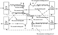
- FIG. 6 is a schematic diagram illustrating the application of a connection switching device in the node of the WDM system in accordance with an embodiment of the present invention.
- the service express refers to cases that protection services of other stations can pass through the present station directly to ensure the services are accurately and precisely transmitted to the destination nodes.
- the service add refers to that the service can be accurately switched to the backup path once the local service is affected.
- the service drop refers to that the service whose destination is the local station can be transmitted to the local station through the backup path once the service is affected in the working path, and the service in the backup path can be accurately imported to the local receiver at the local station.
- connection switching device in an embodiment of the present invention is shown in FIG. 1 .
- the device includes two switches, each of which has two input ports and one output port, and only one of the two input ports can receive the optical signals and output the signals from the output port at one time. It is possible to switch between the two input ports under the control of the switch.
- the input port 1 of the first switch connects to the downlink direction of the working path
- the input port 2 connects to the downlink direction of the backup path
- the output port of the first switch connects to the local drop path
- the local add path is connected to the downlink direction of the working path and the input port 1 of the second switch respectively, the input port 2 of the second switch and the input port 2 of the first switch connect to the downlink direction of the backup path together, and the output port of the second switch connects to the uplink direction of the backup path.
- the first switch chooses to open the input port 1 to the output port, thus the downlink service signals from the working path are directly input to the local drop path, and received by the local station; meanwhile, the uplink service signals of the local station are input to the uplink direction of the working path, and transmitted to the downstream nodes.
- the second switch chooses to open the input port 1 to the output port, ensuring the downlink services from the backup path to continue to be transmitted along the same direction, and thereby achieve the express of the node.
- the first switch selects to open the input port 2 to the output port, and switches the downlink service signals from the backup path to the local drop path, realizing the local drop function and ensuring the normal reception of service signals.
- the second switch selects to open the input port 1 to the output port, to transmit the uplink service signals from the local add path through the backup path, realizing the local add function.
- the function can be implemented in the node with two independent connection switching devices, the architecture is shown as FIG. 2 .
- the first working path and the second working path adopt different wavelengths ⁇ 1 and ⁇ 2 , and are transmitted in different optical fiber lines respectively;
- the first backup path that protects the first working path adopts the wavelength ⁇ 1 to transmit signals in the optical fiber line where the second working path locates, while the second backup path that protects the second working path adopts the wavelength ⁇ 2 to transmit signals in the optical fiber where the first working path locates.
- the connection switching device 1 is configured for connecting and switching the services from the West to the East under normal conditions; and the connection switching device 2 is configured for connecting and switching the services from the West to the East under normal conditions.
- the first switch of connection switching device 1 selects to open the input port 1 , and inputs the downlink service signals from the first working path in the west to the local drop path D 1 ; inputs the uplink service signals, whose destination is the first optical channel in the east, from the local add path A 2 to the first uplink direction of the working path.
- the first switch of connection switching device 2 selects to open the input port 1 , and inputs the downlink service signals from the second working path in the east into the local drop path D 2 ; inputs the uplink service signals, whose destination is the second optical channel in the west, from the local add path A 1 to the uplink direction of the second working path.
- the second switch of connection switching device 1 selects to open the input port 1 to the output port, thereby the downlink service signals from the first backup path in the east can be continuously transmitted along the same direction.
- the second switch of connection switching device 2 selects to open the input port 1 to the output port, thereby the downlink service signals from the second backup path in the west can be continuously transmitted along the same direction.
- the first switch of the connection switching device 1 selects to open the input port 2 to the output port, thereby the downlink service signals from the first backup path in the east can be switched to the local drop path D 1 .
- the first switch of the connection switching device 2 selects to open the input port 2 to the output port, and thereby the downlink service signals from the second backup path in the west can be switched to the local drop path D 2 .
- the second switch of the connection switching device 1 selects to open the input port 1 to the output port, thereby the uplink service signals from the local add path A 2 can be transmitted through the first backup path.
- the second switch of the connection switching device 2 selects to open the input port 1 to the output port, and thereby the uplink service signals from the local add path A 1 can be transmitted through the second backup path.
- connection switching device 1 and the connection switching device 2 in FIG. 2 are independent to each other, therefore, in practical applications, the connection switching device 1 and the connection switching device 2 can implement the three modes of switch operations, i.e. the service express, the service add and the service drop, independently, which can further improve the flexibility of the network protection.
- the distribution of the services is not always uniform, as shown in FIG. 3 , except for the point A, services in all the other nodes in the whole ring network are unsymmetrical, the service add/drop only exists in one direction, therefore, under such circumstances, the preferred embodiment of the present invention provides a connection switching device as shown in FIG. 4A ⁇ 4C .
- connection switching device 1 is used for connecting and switching the downlink services from the west into the local stations under normal conditions
- connection switching device 2 is used for connecting and switching the uplink services from the local stations to the west under normal conditions.
- the connection switching device 1 includes the first switch and the second switch.
- the first switch which has two input ports and one output port, and the input ports can be controlled to switch to each other;
- the input port 1 of the first switch connects to the downlink direction of the first working path,
- the input port 2 connects to the downlink direction of the first backup path, and the output port connects to the local drop path D 1 ;
- the second switch has one input port and one output port, and the input port can be controlled to be open or close to the output port.
- the input port of the second switch connects to the downlink direction of the first backup path.
- the output port connects to the uplink direction of the first backup path.
- the connection switching device 2 includes one switch, which has two input ports and one output port, and the two input ports can be controlled to switch to each other.
- the input port 1 of the switch connects to the local add path A 1
- the output port 2 connects to the downlink direction of the second backup path
- the output port connects to the uplink direction of the second backup path
- the local add path A 1 is connected to the uplink direction of the second working path.
- connection switching device 1 selects to open the input port 1 , and inputs the downlink service signals from the first working path in the west to the local drop path D 1 ; in the connection switching device 2 , input the uplink service signals, whose destination is the second optical channel in the west, from the local add path A 1 to the uplink direction of the second working path.
- the second switch of connection switching device 1 selects to open the input port 1 to the output port, thereby the downlink service signals from the first backup path in the east can be continuously transmitted along the same direction.
- the second switch of connection switching device 2 selects to open the input port 1 to the output port, thereby the downlink service signals from the second backup path in the west can be continuously transmitted along the same direction.
- the first switch of the connection switching device 1 selects to open the input port 2 to the output port, thereby the downlink service signals from the first backup path in the east can be switched to the local drop path D 1 .
- the switch of the connection switching device 2 selects to open the input port 1 to the output port, thereby the uplink service signals from the local add path A 1 can be transmitted through the second backup path.
- connection switching device 1 and the connection switching device 2 in FIG. 2 are independent to each other, therefore, in practical applications, the connection switching device 1 and the connection switching device 2 can implement the three modes of switch operations, i.e. the service express, the service add and the service drop, independently, which can further improve the flexibility of the network protection.
- the node In the ring network there are also some nodes which have no add/drop on the wavelength, in the case, the node can be seen as a transparent node, i.e. the node will not participate any Och-SPRing function of the wavelength pair, and will not do any operations on the wavelength pair, either.
- connection switching device If there is only the unidireactional service drop without the service add in the node, then the structure of the connection switching device is shown in FIG. 4B .
- the node only needs to complete the service drop, and the service express is still supported by the local station at the same time.
- the structure is the same as that in FIG. 4A , i.e., it includes the first switch and the second switch.
- the first switch has two input ports and one output port.
- the input port 1 of the first switch connects to the downlink direction of the first working path
- the input port 2 connects to the downlink direction of the first backup path
- the output port connects to the local drop path D 1 ;
- the second switch has one input port and one output port.
- the input port of the second switch connects to the downlink direction of the first backup path, and the output port connects to the uplink direction of the first backup path.
- the first switch selects to open the input port 1 , and inputs the downlink service signals from the first working path in the west to the local drop path D 1 .
- the second switch selects to open the input port to the output port, thereby the downlink service signals from the first backup path in the east can be continuously transmitted along the same direction.
- the first switch selects to open the input port 2 to the output port, thereby the downlink service signals from the first backup path in the east can be switched to the local drop path D 1 .
- the first switch selects output port 2 to connect with the output port, and switches the downlink service signal sent from the first backup path in the east to local drop path D 1 .
- connection switching device If there is only the unidireactional service add without the service drop in the node, then the structure of the connection switching device is shown in FIG. 4C .
- the node only needs to complete the service add, and the service express is still supported by the local station at the same time.
- the structure is the same as that of the connection switching device 2 shown in FIG. 4A , i.e. it includes one switch, which has two input ports and one output port.
- the input port 1 of the switch connects to the local add path A 1
- the output port 2 connects to the downlink direction of the second backup path
- the output port connects to the uplink direction of the second backup path
- the local add path A 1 is connected to the uplink direction of the second working path.
- the switch selects to open the input port 1 to the output port, thereby the downlink service signals from the second backup path in the west can be continuously transmitted along the same direction.
- the switch selects to open the input port 1 to the output port, thereby the uplink service signals from the local add path A 1 can be transmitted through the second backup path.
- all the switches in the connection switching device can be the optical switches, and can switch to different port under the control of the control system; however, in practice, not all of the switches have to be the optical switches to implement the procedure of connection and switch, it is also applicable to use the 1+1 protection function into OTU together with the protection switch to implement the Och-SPRing.
- the second switch of the two connection switching devices in FIG. 5 are also the optical switch, but the first switch in the working path of the original protection device is replaced by electric switches of the 1+1 protection OTU, the downlink optical signal of the first working path and the downlink optical signal of the first backup path are simultaneously connected to two modules of the 1+1 protection OTU respectively, and then the control system determines which path of signal is effective. Meanwhile, the output port of the 1+1 protection OTU splitting the optical signal into two lines with a 3 dB optical splitter, and simultaneously feeding the signals back to the working path and the backup path.
- the switches are all optical switches, the operation is completely the same.
- the first switch can also be replaced by a logical switch. The principles are the same.
- a 2 need to be transmitted to the input port 1 of the second switch and the uplink direction of the working path respectively, which can be implemented through setting a coupler among the service add path and the input port 1 of the second switch and the uplink direction of the working path, i.e., splitting the optical signals from the service add path into two paths through the coupler and then transmitting the signals to the input port 1 of the second switch and the uplink direction of the working path respectively.
- a 3 dB coupler is a preferred option.
- the input port of the optical switch connects to the service add path, and the two output ports connect to the input port 1 of the second switch and the uplink direction of the working path respectively.
- the signals from the uplink direction of the working path can select to be transmitted through the second switch or the working path under the control of the optical switch.
- the first optical switch can also be replaced by two OTUs.
- the coupler or the 1 ⁇ 2 optical switch or the OUT also can be used for signal splitting and path selection among the backup path and the input port 2 of the first switch and the input port 2 of the second switch.
- the second switch of the connection switching device and the coupler or the optical switch of the backup path can also be replaced by a 2 ⁇ 2 optical switch.
- the two input ports of the 2 ⁇ 2 optical switch connects to the local add path and the downlink direction of the protection path respectively, while the two output ports connect to the input port 2 of the first switch and the uplink direction of the protection path.
- OADM Optical Add-Drop Multiplexing
- the input port of the first OADM unit connects to the transmission optical fiber from the west, and the two output ports of the first OADM connect to the first working path and the second protection path respectively;
- the input port of the fourth OADM unit connects to the transmission optical fiber from the east, and the two output ports connect with the second working path and the first protection path respectively.
- the two input ports of the second OADM unit connect with the first working path and the second protection path respectively, while the output port connects to the transmission optical fiber to the east; the two input ports of the third OADM unit connect to the second working path and the first protection path respectively, while the output port connects to the transmission optical fiber to the west.
- the wavelengths of the first working path and the first backup path are the first wavelength ⁇ 1
- the wavelengths of the second working path and the second backup path are the second wavelength ⁇ 2 .
- the first OADM unit Demultiplexer multiplexes the signal of the wavelength ⁇ 1 and the signal of the wavelength ⁇ 2 from the mixed optical signals containing the wavelengths of ⁇ 1 and ⁇ 2 in the transmission optical fiber from the west, thereafter, transmits the optical signal of the wavelength ⁇ 1 as the optical signal of the first working path to the switch corresponding to the connection switching device 1 , and transmits the optical signal of the wavelength ⁇ 2 as the optical signal of the second backup path to the switch corresponding to the connection switching device 2 .
- the fourth OADM unit Demultiplexer multiplexes the signal of the wavelength ⁇ 1 and the signal of the wavelength ⁇ 2 from the mixed optical signals containing the wavelengths of ⁇ 1 and ⁇ 2 in the transmission optical fiber from the east, thereafter, transmits the optical signal of the wavelength ⁇ 1 as the optical signal of the first working path to the switch corresponding to the connection switching device 1 , and transmits the optical signal of the wavelength ⁇ 2 as the optical signal of the second backup path to the switch corresponding to the connection switching device 2 .
- the second OADM unit combines the optical signals of the wavelength ⁇ 1 of the first working path from the local station to the east, and the optical signals of the wavelength ⁇ 2 of the second backup path from the local station to the east, and then the second OADM unit transmits the mixed signals to the optical fiber to the east.
- the third OADM unit combines the optical signals of the wavelength ⁇ 2 of the first working path from the local station to the west, and the optical signals of the wavelength ⁇ 1 of the first backup path from the local station to the west, and then the second OADM unit transmits the mixed signals to the optical fiber to the west.
- the service express operations can be performed through express paths, which directly connect the first and the second OADM units, and the third and the fourth OADM units.
- the structures of the nodes are similar to FIG. 6 , but it is not necessary to set OADM units in the directions without input/output services.
- the default states of the optical switches in the working path should be connected to the working path, i.e., in all the above-mentioned embodiments, the first switches of the connection switching devices choose to open the input ports 1 .
- the default states of the optical switches in the backup path also choose to connect to the working path, i.e., the second switches of the connection switching devices in FIG. 1 , 2 , 5 , 6 choose to open the input ports 1 ; the connection switching device 1 in FIG. 4A and the connection switching device in FIG. 4B choose to block the second switches.
- connection switching device 2 in FIG. 4A and the switch of the connection switching device shown in FIG. 4C choose to open the input ports 1 . Since at least two nodes in the ring network of the bi-directional Och-SPRing are involved in the protection switch of the wavelength pair, while all the backup paths select to transmit the optical path of the node in the backup path, the ring self-excitation can be avoided on the backup path. Where the ring self-excitation of the optical path penetrated the OADM, at least one parallel OADM node is still necessary in the ring network.
- the transmitting-end Since the optical switches on both of the backup path and the working path select the working path under the normal conditions, however, the transmitting-end always operates in a bridge-state under normal conditions, therefore, once a failure occurs in the line, the receiving-end can confirm the failure, and send a bridge request to the transmitting-end through the backup route.
- the intermediate nodes which have operations on the wavelength pair will switch the state of all the optical switches in the backup path to the backup path, therefore facilitating the optical signals from the transmitting-end to pass through the backup path and reach the destination, while the receiving-end will return a confirmation message to the transmitting-end after receiving the bridge request. And finally the receiving-end switches the optical switch in the working path to the back routes, thereby completing the entire switch process.
Landscapes
- Engineering & Computer Science (AREA)
- Computer Networks & Wireless Communication (AREA)
- Signal Processing (AREA)
- Optical Communication System (AREA)
- Data Exchanges In Wide-Area Networks (AREA)
Applications Claiming Priority (4)
| Application Number | Priority Date | Filing Date | Title |
|---|---|---|---|
| CN200410034507.5 | 2004-04-14 | ||
| CN200410034507 | 2004-04-14 | ||
| CNB2004100345075A CN100370700C (zh) | 2004-04-14 | 2004-04-14 | 波分复用系统中光通道共享保护的实现方法、系统及装置 |
| PCT/CN2005/000502 WO2005101712A1 (fr) | 2004-04-14 | 2005-04-14 | Appareil assurant la protection partagee d'un canal optique dans un systeme de multiplexage en longueur d'onde et procede connexe |
Related Parent Applications (1)
| Application Number | Title | Priority Date | Filing Date |
|---|---|---|---|
| PCT/CN2005/000502 Continuation WO2005101712A1 (fr) | 2004-04-14 | 2005-04-14 | Appareil assurant la protection partagee d'un canal optique dans un systeme de multiplexage en longueur d'onde et procede connexe |
Publications (2)
| Publication Number | Publication Date |
|---|---|
| US20070195693A1 US20070195693A1 (en) | 2007-08-23 |
| US7796502B2 true US7796502B2 (en) | 2010-09-14 |
Family
ID=35150321
Family Applications (1)
| Application Number | Title | Priority Date | Filing Date |
|---|---|---|---|
| US10/589,522 Active 2027-03-28 US7796502B2 (en) | 2004-04-14 | 2005-04-14 | Method and device for implementing Och-Spring in wavelength division multiplexing systems |
Country Status (6)
| Country | Link |
|---|---|
| US (1) | US7796502B2 (de) |
| EP (1) | EP1715609B1 (de) |
| CN (1) | CN100370700C (de) |
| AT (1) | ATE412283T1 (de) |
| DE (1) | DE602005010550D1 (de) |
| WO (1) | WO2005101712A1 (de) |
Cited By (4)
| Publication number | Priority date | Publication date | Assignee | Title |
|---|---|---|---|---|
| US20080292310A1 (en) * | 2005-12-22 | 2008-11-27 | Huawei Technologies Co., Ltd. | Method, Apparatus And System For Optical Channel Group Shared Protection |
| US20090123146A1 (en) * | 2005-01-01 | 2009-05-14 | Congqi Li | Packet Optical Channel Sharing Protection Method Device And System Thereof |
| US20100150565A1 (en) * | 2008-12-17 | 2010-06-17 | Huawei Technologies Co., Ltd. | Method and apparatus for transmitting/receiving signals in a microwave system |
| US8195758B1 (en) * | 2008-10-09 | 2012-06-05 | The United States Of America As Represented By The Secretary Of The Navy | Control for signal redundancy |
Families Citing this family (9)
| Publication number | Priority date | Publication date | Assignee | Title |
|---|---|---|---|---|
| CN1790960B (zh) * | 2005-12-06 | 2010-04-14 | 电子科技大学 | 一种wdm网中混合共享链路波长资源的通路保护方法 |
| CN1874201B (zh) * | 2006-06-20 | 2010-05-12 | 中兴通讯股份有限公司 | 在接收设备共享配置下的光网络保护触发方法及装置 |
| DE102009022365B3 (de) * | 2009-05-22 | 2010-12-09 | Adva Ag Optical Networking | Verfahren und Vorrichtung zur 1+1-Protection einer optischen Übertragungsstrecke |
| WO2013096283A1 (en) * | 2011-12-22 | 2013-06-27 | Tyco Electronices Corporation | Fiber optic wall plate with redundancy system |
| EP3205034A4 (de) | 2014-10-06 | 2018-06-27 | ADC Telecommunications Inc. | Ermöglichung der montage von glasfasernetzen |
| CN105959060B (zh) * | 2016-04-25 | 2018-07-24 | 国网山东省电力公司信息通信公司 | 一种基于组网方式的外置光放大器监控系统及方法 |
| CN110708254B (zh) * | 2018-07-09 | 2023-04-18 | 华为技术有限公司 | 一种业务处理方法、控制设备及存储介质 |
| CN112865914B (zh) * | 2021-02-24 | 2024-05-07 | 中国联合网络通信集团有限公司 | 光波分传送系统及方法 |
| CN115549775B (zh) * | 2022-12-05 | 2023-10-17 | 北京百度网讯科技有限公司 | 光信号传输异常的处理方法、光传输设备及系统 |
Citations (12)
| Publication number | Priority date | Publication date | Assignee | Title |
|---|---|---|---|---|
| US5903370A (en) | 1996-06-28 | 1999-05-11 | Mci Communications Corporation | System for an optical domain |
| US5933258A (en) | 1995-09-06 | 1999-08-03 | Northern Telecom | Optical communication system |
| DE19946487A1 (de) | 1999-09-28 | 2001-05-10 | Siemens Ag | Optisches Protection Modul sowie Schaltungsanordnung zur Realisierung von unterschiedlichen Netzersatzschaltungsfunktionen für optische Netztopologien |
| US20010038473A1 (en) * | 2000-03-10 | 2001-11-08 | Ming-Jun Li | Devices and methods for controlling protection switching in an optical channel shared protection ring |
| WO2002069540A2 (en) | 2000-11-07 | 2002-09-06 | Oni Systems Corp. | Method and system for a bi-directional path switched network |
| DE10126334A1 (de) | 2001-05-30 | 2002-12-12 | Siemens Ag | Optisches Protection-Modul |
| US6701085B1 (en) | 1997-07-22 | 2004-03-02 | Siemens Aktiengesellschaft | Method and apparatus for data transmission in the wavelength-division multiplex method in an optical ring network |
| US20040190901A1 (en) * | 2003-03-29 | 2004-09-30 | Xiaojun Fang | Bi-directional optical network element and its control protocols for WDM rings |
| US6968130B1 (en) * | 1999-09-07 | 2005-11-22 | Nokia Corporation | System and method for fully utilizing available optical transmission spectrum in optical networks |
| US7197241B2 (en) * | 2000-08-25 | 2007-03-27 | Corvis Corporation | Optical transmission systems including optical protection systems, apparatuses, and methods |
| US7356258B1 (en) * | 2002-11-26 | 2008-04-08 | Network Photonics, Inc. | Optical interconnection for traffic between a pair of DWDM rings |
| US7532817B1 (en) * | 2004-06-29 | 2009-05-12 | Lightech Fiberoptics, Inc. | Fiber optic link protection apparatus |
Family Cites Families (3)
| Publication number | Priority date | Publication date | Assignee | Title |
|---|---|---|---|---|
| CN1129261C (zh) * | 1999-07-15 | 2003-11-26 | 华为技术有限公司 | 多安全机制下的同步触发复用段保护倒换和检测方法 |
| CN1136688C (zh) * | 2001-02-27 | 2004-01-28 | 北京邮电大学 | 波分复用线路倒换环通用节点保护装置 |
| JP2003009194A (ja) * | 2001-06-25 | 2003-01-10 | Kddi Corp | 光クロスコネクト装置並びにその制御装置及び方法 |
-
2004
- 2004-04-14 CN CNB2004100345075A patent/CN100370700C/zh not_active Expired - Lifetime
-
2005
- 2005-04-14 US US10/589,522 patent/US7796502B2/en active Active
- 2005-04-14 AT AT05743396T patent/ATE412283T1/de not_active IP Right Cessation
- 2005-04-14 EP EP05743396A patent/EP1715609B1/de not_active Expired - Lifetime
- 2005-04-14 WO PCT/CN2005/000502 patent/WO2005101712A1/zh not_active Ceased
- 2005-04-14 DE DE602005010550T patent/DE602005010550D1/de not_active Expired - Lifetime
Patent Citations (12)
| Publication number | Priority date | Publication date | Assignee | Title |
|---|---|---|---|---|
| US5933258A (en) | 1995-09-06 | 1999-08-03 | Northern Telecom | Optical communication system |
| US5903370A (en) | 1996-06-28 | 1999-05-11 | Mci Communications Corporation | System for an optical domain |
| US6701085B1 (en) | 1997-07-22 | 2004-03-02 | Siemens Aktiengesellschaft | Method and apparatus for data transmission in the wavelength-division multiplex method in an optical ring network |
| US6968130B1 (en) * | 1999-09-07 | 2005-11-22 | Nokia Corporation | System and method for fully utilizing available optical transmission spectrum in optical networks |
| DE19946487A1 (de) | 1999-09-28 | 2001-05-10 | Siemens Ag | Optisches Protection Modul sowie Schaltungsanordnung zur Realisierung von unterschiedlichen Netzersatzschaltungsfunktionen für optische Netztopologien |
| US20010038473A1 (en) * | 2000-03-10 | 2001-11-08 | Ming-Jun Li | Devices and methods for controlling protection switching in an optical channel shared protection ring |
| US7197241B2 (en) * | 2000-08-25 | 2007-03-27 | Corvis Corporation | Optical transmission systems including optical protection systems, apparatuses, and methods |
| WO2002069540A2 (en) | 2000-11-07 | 2002-09-06 | Oni Systems Corp. | Method and system for a bi-directional path switched network |
| DE10126334A1 (de) | 2001-05-30 | 2002-12-12 | Siemens Ag | Optisches Protection-Modul |
| US7356258B1 (en) * | 2002-11-26 | 2008-04-08 | Network Photonics, Inc. | Optical interconnection for traffic between a pair of DWDM rings |
| US20040190901A1 (en) * | 2003-03-29 | 2004-09-30 | Xiaojun Fang | Bi-directional optical network element and its control protocols for WDM rings |
| US7532817B1 (en) * | 2004-06-29 | 2009-05-12 | Lightech Fiberoptics, Inc. | Fiber optic link protection apparatus |
Non-Patent Citations (1)
| Title |
|---|
| Tatsuya Shiragaki et al; "Protection architecture and applications of Och shared protection ring." Optical Networks Magazine Jul./Aug. 2001. |
Cited By (6)
| Publication number | Priority date | Publication date | Assignee | Title |
|---|---|---|---|---|
| US20090123146A1 (en) * | 2005-01-01 | 2009-05-14 | Congqi Li | Packet Optical Channel Sharing Protection Method Device And System Thereof |
| US8103161B2 (en) | 2005-01-01 | 2012-01-24 | Huawei Technologies Co., Ltd. | Method, device and system for group optical channel shared protection |
| US20080292310A1 (en) * | 2005-12-22 | 2008-11-27 | Huawei Technologies Co., Ltd. | Method, Apparatus And System For Optical Channel Group Shared Protection |
| US8195758B1 (en) * | 2008-10-09 | 2012-06-05 | The United States Of America As Represented By The Secretary Of The Navy | Control for signal redundancy |
| US20100150565A1 (en) * | 2008-12-17 | 2010-06-17 | Huawei Technologies Co., Ltd. | Method and apparatus for transmitting/receiving signals in a microwave system |
| US8385745B2 (en) * | 2008-12-17 | 2013-02-26 | Huawei Technologies Co., Ltd. | Method and apparatus for transmitting/receiving signals in a microwave system |
Also Published As
| Publication number | Publication date |
|---|---|
| US20070195693A1 (en) | 2007-08-23 |
| DE602005010550D1 (de) | 2008-12-04 |
| EP1715609A4 (de) | 2007-05-23 |
| EP1715609A1 (de) | 2006-10-25 |
| WO2005101712A1 (fr) | 2005-10-27 |
| CN100370700C (zh) | 2008-02-20 |
| ATE412283T1 (de) | 2008-11-15 |
| EP1715609B1 (de) | 2008-10-22 |
| CN1684381A (zh) | 2005-10-19 |
Similar Documents
| Publication | Publication Date | Title |
|---|---|---|
| US7280470B2 (en) | Ring network for sharing protection resource by working communication paths | |
| US6701085B1 (en) | Method and apparatus for data transmission in the wavelength-division multiplex method in an optical ring network | |
| US7072580B2 (en) | Autoprotected optical communication ring network | |
| US7925165B2 (en) | Packet and optical routing equipment and method | |
| EP2493096B1 (de) | Verfahren, system und vorrichtung für den schutz eines bidirektionalen einzelfaserringnetzes | |
| US7796502B2 (en) | Method and device for implementing Och-Spring in wavelength division multiplexing systems | |
| WO2008019608A1 (en) | Method, system and apparatus for protecting wavelength division multiplex transmission | |
| US10498479B2 (en) | Reconfigurable add/drop multiplexing in optical networks | |
| JP4418252B2 (ja) | リング型光ネットワークにおける信号送受信方法及び同ネットワークに用いられる光伝送ノード | |
| JP4899589B2 (ja) | 光ネットワーク、光ネットワークのプロテクション方法及びノード | |
| CN115499728A (zh) | 一种全光交换系统及全光交换方法 | |
| EP1453234A2 (de) | Vorrichtung und Verfahren zur optischen Kommunikation | |
| US20040213572A1 (en) | Optical ring network for burst data communication | |
| WO2007071200A1 (en) | A method, equipment and system for sharing protection of grouped optical channels | |
| JP2000078176A (ja) | 通信ネットワ―ク及び通信ネットワ―ク・ノ―ド装置 | |
| JP4408806B2 (ja) | Wdmネットワークのためのパス保護の方法及びそれに応じたノード | |
| CN1815932B (zh) | 光网络系统和传输装置 | |
| JP2000004460A (ja) | 光通信ノードおよび光通信ネットワーク | |
| US7715711B2 (en) | Wavelength selective switch design configurations for mesh light-trails | |
| US7020078B2 (en) | Communication network system and communication network node for use in the same communication network system | |
| CN1859062B (zh) | 一种波长转换单元共享保护方法、实现装置和应用系统 | |
| WO2024053016A1 (ja) | 通信システム、および制御方法 | |
| JP2011259381A (ja) | 光経路制御方法 | |
| JP2005295464A (ja) | 光伝送システム | |
| JP2004254339A (ja) | 通信ネットワーク及び通信ネットワーク・ノード装置 |
Legal Events
| Date | Code | Title | Description |
|---|---|---|---|
| AS | Assignment |
Owner name: HUAWEI TECHNOLOGIES CO., LTD., CHINA Free format text: ASSIGNMENT OF ASSIGNORS INTEREST;ASSIGNOR:LI, CONGQI;REEL/FRAME:018523/0464 Effective date: 20060831 |
|
| STCF | Information on status: patent grant |
Free format text: PATENTED CASE |
|
| FPAY | Fee payment |
Year of fee payment: 4 |
|
| MAFP | Maintenance fee payment |
Free format text: PAYMENT OF MAINTENANCE FEE, 8TH YEAR, LARGE ENTITY (ORIGINAL EVENT CODE: M1552) Year of fee payment: 8 |
|
| MAFP | Maintenance fee payment |
Free format text: PAYMENT OF MAINTENANCE FEE, 12TH YEAR, LARGE ENTITY (ORIGINAL EVENT CODE: M1553); ENTITY STATUS OF PATENT OWNER: LARGE ENTITY Year of fee payment: 12 |