US7794581B2 - Process for the surface treatment of a component, and apparatus for the surface treatment of a component - Google Patents
Process for the surface treatment of a component, and apparatus for the surface treatment of a component Download PDFInfo
- Publication number
- US7794581B2 US7794581B2 US11/170,662 US17066205A US7794581B2 US 7794581 B2 US7794581 B2 US 7794581B2 US 17066205 A US17066205 A US 17066205A US 7794581 B2 US7794581 B2 US 7794581B2
- Authority
- US
- United States
- Prior art keywords
- component
- voltage
- treatment
- measurement
- surface treatment
- Prior art date
- Legal status (The legal status is an assumption and is not a legal conclusion. Google has not performed a legal analysis and makes no representation as to the accuracy of the status listed.)
- Expired - Fee Related, expires
Links
Images




Classifications
-
- C—CHEMISTRY; METALLURGY
- C25—ELECTROLYTIC OR ELECTROPHORETIC PROCESSES; APPARATUS THEREFOR
- C25F—PROCESSES FOR THE ELECTROLYTIC REMOVAL OF MATERIALS FROM OBJECTS; APPARATUS THEREFOR
- C25F7/00—Constructional parts, or assemblies thereof, of cells for electrolytic removal of material from objects; Servicing or operating
-
- C—CHEMISTRY; METALLURGY
- C25—ELECTROLYTIC OR ELECTROPHORETIC PROCESSES; APPARATUS THEREFOR
- C25D—PROCESSES FOR THE ELECTROLYTIC OR ELECTROPHORETIC PRODUCTION OF COATINGS; ELECTROFORMING; APPARATUS THEREFOR
- C25D21/00—Processes for servicing or operating cells for electrolytic coating
- C25D21/12—Process control or regulation
-
- C—CHEMISTRY; METALLURGY
- C25—ELECTROLYTIC OR ELECTROPHORETIC PROCESSES; APPARATUS THEREFOR
- C25F—PROCESSES FOR THE ELECTROLYTIC REMOVAL OF MATERIALS FROM OBJECTS; APPARATUS THEREFOR
- C25F5/00—Electrolytic stripping of metallic layers or coatings
Definitions
- the invention relates to a process for the surface treatment of a component in accordance with the preamble of claim 1 and to an apparatus for carrying out a process for the surface treatment of a component.
- Components which are subject to operating loads such as for example turbine blades and vanes of gas turbines, are subjected to an electrolyte treatment, so that the component can then be refurbished.
- the MCrAlX layers on the component which are subject to operating loads, are removed by being immersed in 20% strength hydrochloric acid at approx. 50°-80° C. After a period of time derived from values gained through experience, the blades or vanes are removed from the acid bath, rinsed with water and then abrasively blasted. The process sequence of electrolyte bath followed by blasting is repeated a number of times until the entire MCrAlX layer has been removed or dissolved.
- the time for which the blades or varies remain in the electrolyte does not in this case reflect the time which is actually required for the individual blade or vane to conclude the dissolution process, but rather is set as standard to a specific time.
- the residence time in the electrolyte is in this case determined on the basis of general empirical values.
- each individual component is subject to different levels of load, which means that a fixed preset time leads to different or incomplete dissolution of the surface of the component which is subject to load.
- the components remain in the acid bath until the predetermined period of time has elapsed without any further progress being made in the removal of the coating.
- EP 1 094 134 A1 and US 2003/0062271 A1 disclose processes for the electrochemical removal of layers.
- U.S. Pat. No. 4,539,087 discloses a method in which the current of an electrolytic process is measured, so that on the basis of the current profile it is possible to reach a decision as to when to terminate the process.
- a further object of the invention is to provide an apparatus which allows the minimum treatment times required to be determined individually for each individual component.
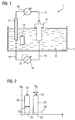
- FIG. 1 shows an apparatus for carrying out the process according to the invention
- FIGS. 2 , 3 , 4 show a time/voltage profile
- FIGS. 5 , 6 show time profiles for voltages and current which result when carrying out the process according to the invention
- FIG. 7 shows a turbine blade or vane
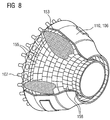
- FIG. 8 shows a combustion chamber
- FIG. 9 shows a gas turbine
- FIG. 1 shows an example of an apparatus 1 according to the invention which can be used to carry out the process according to the invention.
- the apparatus 1 comprises a vessel 3 , for example metallic, ceramic or made from plastic (Teflon polymer, etc.), in which there is a treatment agent 6 , for example an acid 6 or an electrolyte 6 (comprising coating material), which is used for the surface treatment of, such as the removal of a coating from or application of a coating to, at least one component 9 .
- a treatment agent 6 for example an acid 6 or an electrolyte 6 (comprising coating material), which is used for the surface treatment of, such as the removal of a coating from or application of a coating to, at least one component 9 .
- an acid or an acid mixture it is preferable for an acid or an acid mixture to be present in the vessel 3 .
- the electrolyte 6 includes the corresponding chemical elements for the coating.
- a single component 9 the surface region of which is to be dissolved, is arranged in the treatment agent 6 . This dissolution is effected, for example, by the acid attack on, for example, the surface of the component 9 which is subject to operating loads.
- the coating is to be removed from two or more components 9 , by way of example the two components 9 in each case form an electrode (i.e. anode and cathode), and in this case the treatment agent 6 used should be a nitrogen-containing treatment agent 6 .
- there is at least one voltage/current source 18 which is electrically connected to the component 9 and a further electrode 12 via electrical connection means 15 .
- a first circuit can be closed by the connection means 15 being connected to a further electrical pole, i.e. the electrode 12 , which is arranged in the treatment agent 6 or connected to the vessel 3 , so that a current I can flow between component 9 and the pole 3 , 12 and can also be measured.
- the current flows across the component 9 via the surface of the component 9 which is subjected to load and then flows through the treatment agent 6 to the electrode 12 (or to the vessel 3 ).
- a plurality of components 9 can be arranged in a vessel 3 in order for their coating to be removed, in which case a current curve I(t) can be determined individually for each component 9 , so that the components 9 if appropriate remain in the treatment agent 6 for different lengths of time.
- a further second circuit comprising lines 15 ′ and current/voltage source 18 ′, for example for a measurement voltage 33 ( FIG. 2 ), may also be present in accordance with the invention, so that a current likewise flows through this circuit and can also be measured.
- the lines 15 ′ are then likewise connected to the component 9 and the electrode 12 .
- FIG. 2 shows an example of a voltage profile according to the invention.
- a pulsed treatment voltage 30 with a pulse duration t 30 is applied, generating currents of up to 100 A, for example, for correspondingly large components 9 (length 38 cm), such as gas turbine blades or vanes 120 , 130 ( FIGS. 7 , 9 ).
- the pulse duration t 30 may always be the same or may change with time t.
- the magnitude of the treatment voltage may also change with time t.
- a lower, for example pulsed, measurement voltage 33 (1 mV to 50 mV) is superimposed on the higher treatment voltage 30 (for removal of the coating) in the circuit ( 18 , 15 , 9 , 6 , 12 ), or the treatment voltage 30 is briefly (i.e. at least at times) increased by the magnitude of the measurement voltage 33 .
- the pulse duration t 33 of the measurement voltage 33 may be shorter than, equal to or longer than the pulse duration t 30 of the treatment voltage 30 .
- the measurement voltage 33 may be applied at the start, in the middle or at the end of the pulsed treatment voltage 33 .
- the lower measurement voltage 33 generates very much lower currents, which can be measured more successfully.
- the signals relating to the treatment voltage 30 and the measurement voltage 33 are separated, for example, by analysis of the current curve by means of mathematical signal separation methods, such as for example Fourier analysis.
- the lines 15 ′ are likewise connected to the component 9 and, for example, to the electrode 12 ′ (indicated by dashed lines) and not to the electrode 12 ), in which case the voltages are superimposed on the large surface.
- the separation of the current signals by measurement means is effected, for example, by the use of two partially decoupled circuits ( 15 + 18 + 9 + 6 + 12 ; 15 ′+ 18 ′+ 9 + 6 + 12 or + 12 ′).
- FIG. 3 shows a further example of a voltage profile according to the invention for the method according to the invention.
- a high pulsed treatment voltage 30 which generates very high currents, is used to remove the coating.
- the measurement voltage 33 is in this case, for example, likewise pulsed and is applied during the interpulse periods 36 (t 36 ) of the treatment voltage pulses 30 (t 36 >t 33 ). This is done by synchronizing the voltage pulses 30 , 33 .
- FIG. 4 shows examples of further voltage profiles.
- a treatment voltage 30 of a constant level (DC voltage) is applied to the component 9 for electrolytic coating removal, while the measurement voltage 33 is once again pulsed and superimposed on the treatment voltage 30 .
- the treatment voltage 30 can be briefly increased (corresponding to a pulsed increase) by the magnitude of the measurement voltage 33 , in which case only one circuit is required, or alternatively the measurement voltage 33 ′ (indicated by dashed lines) is superimposed on the treatment voltage, for example by a second circuit.
- a time profile of the current I(t) caused by the measurement voltage during electrolysis for coating removal is illustrated in FIG. 5 .
- the current I(t) initially rises with time t and after a certain point in time is initially substantially constant.
- the coating removal is not yet complete, i.e. the coating removal rate is still high.
- the current I drops.
- the drop (range or point 27 in curve I(t)) in the current I indicates that only a small amount of coating material is being dissolved. Consequently, the dissolution process can be stopped when, for example, a predetermined comparison value for the current intensity has been reached or the current intensity drops by a certain amount (cf. difference between measurement points 27 , 22 ) or when a trend line indicates a falling profile for the current intensity.
- the process can also be carried out in substeps.
- an abrasive coating removal is in each case carried out, removing residues of acid products and/or accelerating the coating removal, since after a certain residence time of the component 9 in the treatment agent 6 , by way of example, a brittle layer forms, which can be removed more successfully by abrasive means.
- the component 9 prefferably washed (rinsed) in a process intermediate step.
- the component 9 is once again positioned in the treatment agent 6 .
- the process steps of treatment of the component 9 in the treatment agent 6 and abrasive blasting can be repeated as desired.
- the removal of the coating from the component(s) 9 proceeds even without the presence of a treatment voltage, i.e. the coating removal process is not at that time electrolytic.
- FIG. 6 shows an experimentally determined profile for the currents and voltages measured or used.
- a constant treatment voltage 30 of 1.2 V is applied to a turbine blade or vane (length ⁇ 18 cm, surface area ⁇ 150 cm 2 ); the electrolyte used is, for example, 5% HCl (hydrochloric acid) containing 2% triethanolamine.
- the treatment voltage 30 is represented by the diamond shapes and generates a current I of 10 to 11 A (not shown).
- the pulsed measurement voltage 33 for determining the end point is in this case, for example, 50 mV and is applied by pulses with a pulse length of, for example, 0.5 s.
- the ratio of the measurement voltage 33 to the treatment voltage 30 is therefore 1:24; alternatively it may, for example, be 1:10 (or 1:20, 1:30 or greater than 1:50, 1:100).
- the measurement voltage 33 is represented by squares in FIG. 6 .
- the current I which is measured as a result of the measurement voltage 33 , is represented by the triangles in FIG. 6 .
- a separating line (indicated in dashed lines) shows the intrapolated and expected time profile of the current. This curve corresponds to that shown in FIG. 2 .
- the time profile 24 of the current I(t) can also be determined from individual measurement points 21 which are taken at regular or irregular intervals.
- FIG. 7 shows a perspective view of a blade or vane 120 , 130 which extends along a longitudinal axis 121 .
- the blade or vane as an example of the component 9 may be a rotor blade 120 or a guide vane 130 of a turbomachine.
- the turbomachine may be a gas turbine of an aircraft or a power plant for generation of electricity, a steam turbine or a compressor.
- the blade or vane 120 , 130 includes, in succession along the longitudinal axis 121 , a securing region 400 , an adjoining blade or vane platform 403 and a main blade or vane part 406 .
- the vane When used as a guide vane 130 , the vane may have a further platform (not shown) at its vane tip 415 .
- a blade or vane root 183 which is used to secure the rotor blades 120 , 130 to a shaft or a disk (not shown).
- the blade or vane root 183 is designed, for example, in the shape of a hammerhead.
- Other configurations, such as a fir-tree root or a dovetail root, are also possible.
- the blade or vane 120 , 130 has a leading edge 409 and a trailing edge 412 with respect to a medium which flows past the main blade or vane part 406 .
- the blade or vane 120 , 130 can in this case be produced by a casting process, or also by means of directional solidification, by means of a forging process, by means of a milling process or by combinations thereof.
- Workpieces with a single-crystal structure or structures are used as components for machines which are exposed to high mechanical, thermal and/or chemical loads in operation.
- Single-crystal workpieces of this type are produced, for example, by directional solidification from the melt. This involves casting processes in which the liquid metal alloy solidifies to form a single-crystal structure, i.e. a single-crystal workpiece, or solidifies directionally.
- dendritic crystals are oriented along the heat flow direction and form either a columnar grain structure (i.e. grains which extend over the entire length of the workpiece and are in this case referred to as directionally solidified, in accordance with the standard terminology employed in the field) or a single-crystal structure, i.e. the entire workpiece comprises a single crystal.
- a columnar grain structure i.e. grains which extend over the entire length of the workpiece and are in this case referred to as directionally solidified, in accordance with the standard terminology employed in the field
- a single-crystal structure i.e. the entire workpiece comprises a single crystal.
- Refurbishment means that protective layers may have to be removed (e.g. by sandblasting) from components 120 , 130 after they have been used, by the process according to the invention. This is followed by removal of the corrosion and/or oxidation layers or products. If appropriate, cracks in the component 120 , 130 are also repaired. This is followed by further coating of the component 120 , 130 , for example by the process according to the invention, and renewed use of the component 120 , 130 .
- the blade or vane 120 , 130 may be of hollow or solid design. If the blade or vane 120 , 130 is to be cooled, it is hollow and may also include film-cooling holes (not shown). To protect against corrosion, the blade or vane 120 , 130 by way of example has corresponding, generally metallic coatings, and, to protect against heat, generally also a ceramic coating.
- FIG. 8 shows a combustion chamber 110 of a gas turbine.
- the combustion chamber 110 is configured, for example, as what is known as an annular combustion chamber, in which a large number of burners 102 arranged circumferentially around the turbine shaft 103 open out in a common combustion-chamber space.
- the combustion chamber 110 overall is configured as an annular structure positioned around the turbine shaft 103 .
- the combustion chamber 110 is designed for a relatively high temperature of the working medium M of approximately 1000° C. to 1600° C.
- the combustion chamber wall 153 is provided, on its side facing the working medium M, with an inner lining formed from heat shield elements 155 (a further example of component 9 ).
- each heat shield element 155 is equipped with a particularly heat-resistant protective layer or is made from material which is able to withstand high temperatures.
- a cooling system is provided for the heat shield elements 155 or for the holding elements thereof.
- the materials of the combustion chamber wall and their coatings may be similar to the turbine blades or vanes.
- FIG. 9 shows, by way of example, a gas turbine 100 in the form of a longitudinal part-section.
- the gas turbine 100 has a rotor 103 which is mounted such that it can rotate about an axis of rotation 102 and is also referred to as the turbine rotor.
- the annular combustion chamber 106 is in communication with a, for example, annular hot-gas duct 111 , where, for example, four turbine stages 112 in succession form the turbine 108 .
- Each turbine stage 112 is formed, for example, from two blade/vane rings. As seen in the direction of flow of a working medium 113 in the hot-gas duct 111 , a row of guide vanes 115 is followed by a row 125 of rotor blades 120 .
- the guide vanes 130 are secured to an inner casing 138 of a stator 143 , whereas the rotor blades 120 belonging to a row 125 are, for example, fitted to the rotor 103 by means of a turbine disk 133 .
- a generator or machine (not shown) is coupled to the rotor 103 .
- the compressor 105 While the gas turbine 100 is operating, the compressor 105 sucks in air 135 through the intake casing 104 and compresses it. The compressed air provided at the turbine-side end of the compressor 105 is passed to the burners 107 , where it is mixed with a fuel. The mixture is then burnt so as to form the working medium 113 in the combustion chamber 110 . From there, the working medium 113 flows along the hot-gas duct 111 past the guide vanes 130 and the rotor blades 120 . At the rotor blades 120 , the working medium 113 expands, transferring its momentum, so that the rotor blades 120 drive the rotor 103 and the latter in turn drives the machine coupled to it.
- the components exposed to the hot working medium 113 are subject to thermal loads when the gas turbine 100 is operating.
- the guide vanes 130 and rotor blades 120 of the first turbine stage 112 as seen in the direction of flow of the working medium 113 , together with the heat shield bricks lining the annular combustion chamber 106 , are subject to the highest thermal loads.
- these components can be cooled by means of a coolant.
- substrates of the components prefferably have a directional structure, i.e. for them to be in single-crystal form (SX structure) or to have only longitudinally directed grains (DS structure).
- SX structure single-crystal form
- DS structure only longitudinally directed grains
- iron-base, nickel-base or cobalt-base superalloys are used as material for the components, in particular for the turbine blade or vane 120 , 130 and components of the combustion chamber 110 .
- blades or vanes 120 , 130 may have coatings to protect against corrosion (MCrAlX; M is at least one element selected from the group consisting of iron (Fe), cobalt (Co), nickel (Ni), X is an active element and stands for yttrium (Y) and/or silicon and/or at least one rare earth) and against heat (thermal barrier coating).
- M is at least one element selected from the group consisting of iron (Fe), cobalt (Co), nickel (Ni)
- X is an active element and stands for yttrium (Y) and/or silicon and/or at least one rare earth) and against heat (thermal barrier coating).
- the thermal barrier coating consists, for example, of ZrO 2 , Y 2 O 4 —ZrO 2 , i.e. it is not stabilized, or is partially or completely stabilized by yttrium oxide and/or calcium oxide and/or magnesium oxide.
- Columnar grains are produced in the thermal barrier coating by suitable coating processes, such as for example electron beam physical vapor deposition (EB-PVD).
- EB-PVD electron beam physical vapor deposition
- the guide vane 130 has a guide vane root (not shown here) facing the inner casing 138 of the turbine 108 , and a guide vane head at the opposite end from the guide vane root.
- the guide vane head faces the rotor 103 and is fixed to a securing ring 140 of the stator 143 .
Landscapes
- Chemical & Material Sciences (AREA)
- Engineering & Computer Science (AREA)
- Chemical Kinetics & Catalysis (AREA)
- Electrochemistry (AREA)
- Materials Engineering (AREA)
- Metallurgy (AREA)
- Organic Chemistry (AREA)
- Automation & Control Theory (AREA)
- Turbine Rotor Nozzle Sealing (AREA)
- Cleaning And De-Greasing Of Metallic Materials By Chemical Methods (AREA)
- Electrical Discharge Machining, Electrochemical Machining, And Combined Machining (AREA)
Applications Claiming Priority (3)
| Application Number | Priority Date | Filing Date | Title |
|---|---|---|---|
| EP04015424.7 | 2004-06-30 | ||
| EP04015424A EP1612299B1 (de) | 2004-06-30 | 2004-06-30 | Verfahren und Vorrichtung zur Oberflächenbehandlung eines Bauteils |
| EP04015424 | 2004-06-30 |
Publications (2)
| Publication Number | Publication Date |
|---|---|
| US20060084190A1 US20060084190A1 (en) | 2006-04-20 |
| US7794581B2 true US7794581B2 (en) | 2010-09-14 |
Family
ID=34925563
Family Applications (1)
| Application Number | Title | Priority Date | Filing Date |
|---|---|---|---|
| US11/170,662 Expired - Fee Related US7794581B2 (en) | 2004-06-30 | 2005-06-29 | Process for the surface treatment of a component, and apparatus for the surface treatment of a component |
Country Status (5)
| Country | Link |
|---|---|
| US (1) | US7794581B2 (de) |
| EP (1) | EP1612299B1 (de) |
| CN (1) | CN1721580A (de) |
| AT (1) | ATE389739T1 (de) |
| DE (1) | DE502004006578D1 (de) |
Cited By (2)
| Publication number | Priority date | Publication date | Assignee | Title |
|---|---|---|---|---|
| US20070080072A1 (en) * | 2003-05-02 | 2007-04-12 | Ursus Kruger | Method for removing layers from a component |
| US20150001086A1 (en) * | 2013-07-01 | 2015-01-01 | General Electric Company | Method and apparatus for refurbishing turbine components |
Families Citing this family (5)
| Publication number | Priority date | Publication date | Assignee | Title |
|---|---|---|---|---|
| DE102010046372A1 (de) * | 2010-09-24 | 2012-03-29 | Oerlikon Trading Ag, Trübbach | Verfahren zum Entschichten von Werkstücken |
| CN103088398B (zh) * | 2011-10-31 | 2016-05-11 | 通用电气公司 | 多通道电化学去金属涂层系统及其控制电路 |
| CN104593830A (zh) * | 2013-11-01 | 2015-05-06 | 无锡华臻新能源科技有限公司 | 带测量反馈的电化学增材制造方法及装置 |
| CN105033372B (zh) * | 2015-09-01 | 2017-09-01 | 太原科技大学 | 回转类刀具电解钝化装置 |
| CN111715605B (zh) * | 2019-03-22 | 2022-02-08 | 潍坊华光光电子有限公司 | 一种光学镀膜夹具的清洗装置及清洗方法 |
Citations (20)
| Publication number | Priority date | Publication date | Assignee | Title |
|---|---|---|---|---|
| US4539087A (en) | 1982-10-29 | 1985-09-03 | Latszereszeti Eszkozok Gyara | Method for electrolytic removal of galvanic nickel, chromium or gold layers from the surface of a copper or copper alloy base and apparatus for carrying out the method |
| US4713153A (en) | 1985-07-12 | 1987-12-15 | N. V. Bekaert S. A. | Process and apparatus for cleaning by electrochemical pickling with alternating current of specified frequency |
| EP0892090A1 (de) | 1997-02-24 | 1999-01-20 | Sulzer Innotec Ag | Verfahren zum Herstellen von einkristallinen Strukturen |
| WO1999067435A1 (en) | 1998-06-23 | 1999-12-29 | Siemens Aktiengesellschaft | Directionally solidified casting with improved transverse stress rupture strength |
| US6024792A (en) | 1997-02-24 | 2000-02-15 | Sulzer Innotec Ag | Method for producing monocrystalline structures |
| WO2000044949A1 (en) | 1999-01-28 | 2000-08-03 | Siemens Aktiengesellschaft | Nickel base superalloy with good machinability |
| EP1094134A1 (de) | 1999-10-18 | 2001-04-25 | General Electric Company | Elektrochemische Vorrichtung und Verfahren zum Abziehen von metallischen Überzügen |
| US20030062271A1 (en) | 2001-09-28 | 2003-04-03 | Kool Lawrence Bernard | Method and apparatus for selectively removing coatings from substrates |
| EP1306454A1 (de) | 2001-10-24 | 2003-05-02 | Siemens Aktiengesellschaft | Rhenium enthaltende Schutzschicht zum Schutz eines Bauteils gegen Korrosion und Oxidation bei hohen Temperaturen |
| US20030109198A1 (en) * | 2000-08-30 | 2003-06-12 | Whonchee Lee | Methods and apparatus for electrically detecting characteristics of a microelectronic substrate and/or polishing medium |
| EP1319729A1 (de) | 2001-12-13 | 2003-06-18 | Siemens Aktiengesellschaft | Hochtemperaturbeständiges Bauteil aus einkristalliner oder polykristalliner Nickel-Basis-Superlegierung |
| WO2003085174A2 (de) | 2002-04-08 | 2003-10-16 | Siemens Aktiengesellschaft | Vorrichtung und verfahren zur entfernung von oberflächenbereichen eines bauteils |
| EP1204776B1 (de) | 1999-07-29 | 2004-06-02 | Siemens Aktiengesellschaft | Hochtemperaturbeständiges bauteil und verfahren zur herstellung des hochtemperaturbeständigen bauteils |
| US20040104128A1 (en) * | 2001-11-30 | 2004-06-03 | Shuzo Sato | Polishing method and electropolishing apparatus |
| US20040188273A1 (en) * | 2000-08-04 | 2004-09-30 | Takeshi Nogami | Electrolytic polishing apparatus, electrolytic polishing method, and wafer subject to polishing |
| EP1473387A1 (de) | 2003-05-02 | 2004-11-03 | Siemens Aktiengesellschaft | Verfahren zur Entschichtung eines Bauteils |
| US20050098445A1 (en) * | 2003-11-10 | 2005-05-12 | General Electric Company | Electrochemical machining method, tool assembly, and monitoring method |
| US20050167266A1 (en) * | 2004-02-02 | 2005-08-04 | Cabot Microelectronics Corporation | ECMP system |
| US20060163074A1 (en) * | 2002-09-16 | 2006-07-27 | Applied Materials, Inc. | Algorithm for real-time process control of electro-polishing |
| US7232760B2 (en) * | 1999-09-07 | 2007-06-19 | Sony Corporation | Method for producing semiconductor device, polishing apparatus, and polishing method |
-
2004
- 2004-06-30 DE DE502004006578T patent/DE502004006578D1/de not_active Expired - Lifetime
- 2004-06-30 EP EP04015424A patent/EP1612299B1/de not_active Expired - Lifetime
- 2004-06-30 AT AT04015424T patent/ATE389739T1/de not_active IP Right Cessation
-
2005
- 2005-06-28 CN CNA2005100813633A patent/CN1721580A/zh active Pending
- 2005-06-29 US US11/170,662 patent/US7794581B2/en not_active Expired - Fee Related
Patent Citations (21)
| Publication number | Priority date | Publication date | Assignee | Title |
|---|---|---|---|---|
| US4539087A (en) | 1982-10-29 | 1985-09-03 | Latszereszeti Eszkozok Gyara | Method for electrolytic removal of galvanic nickel, chromium or gold layers from the surface of a copper or copper alloy base and apparatus for carrying out the method |
| US4713153A (en) | 1985-07-12 | 1987-12-15 | N. V. Bekaert S. A. | Process and apparatus for cleaning by electrochemical pickling with alternating current of specified frequency |
| EP0892090A1 (de) | 1997-02-24 | 1999-01-20 | Sulzer Innotec Ag | Verfahren zum Herstellen von einkristallinen Strukturen |
| US6024792A (en) | 1997-02-24 | 2000-02-15 | Sulzer Innotec Ag | Method for producing monocrystalline structures |
| WO1999067435A1 (en) | 1998-06-23 | 1999-12-29 | Siemens Aktiengesellschaft | Directionally solidified casting with improved transverse stress rupture strength |
| WO2000044949A1 (en) | 1999-01-28 | 2000-08-03 | Siemens Aktiengesellschaft | Nickel base superalloy with good machinability |
| EP1204776B1 (de) | 1999-07-29 | 2004-06-02 | Siemens Aktiengesellschaft | Hochtemperaturbeständiges bauteil und verfahren zur herstellung des hochtemperaturbeständigen bauteils |
| US7232760B2 (en) * | 1999-09-07 | 2007-06-19 | Sony Corporation | Method for producing semiconductor device, polishing apparatus, and polishing method |
| EP1094134A1 (de) | 1999-10-18 | 2001-04-25 | General Electric Company | Elektrochemische Vorrichtung und Verfahren zum Abziehen von metallischen Überzügen |
| US20040188273A1 (en) * | 2000-08-04 | 2004-09-30 | Takeshi Nogami | Electrolytic polishing apparatus, electrolytic polishing method, and wafer subject to polishing |
| US20030109198A1 (en) * | 2000-08-30 | 2003-06-12 | Whonchee Lee | Methods and apparatus for electrically detecting characteristics of a microelectronic substrate and/or polishing medium |
| US20030062271A1 (en) | 2001-09-28 | 2003-04-03 | Kool Lawrence Bernard | Method and apparatus for selectively removing coatings from substrates |
| EP1306454A1 (de) | 2001-10-24 | 2003-05-02 | Siemens Aktiengesellschaft | Rhenium enthaltende Schutzschicht zum Schutz eines Bauteils gegen Korrosion und Oxidation bei hohen Temperaturen |
| US20040104128A1 (en) * | 2001-11-30 | 2004-06-03 | Shuzo Sato | Polishing method and electropolishing apparatus |
| EP1319729A1 (de) | 2001-12-13 | 2003-06-18 | Siemens Aktiengesellschaft | Hochtemperaturbeständiges Bauteil aus einkristalliner oder polykristalliner Nickel-Basis-Superlegierung |
| WO2003085174A2 (de) | 2002-04-08 | 2003-10-16 | Siemens Aktiengesellschaft | Vorrichtung und verfahren zur entfernung von oberflächenbereichen eines bauteils |
| DE10259365A1 (de) | 2002-04-08 | 2003-10-30 | Siemens Ag | Vorrichtung und Verfahren zur Entfernung von Oberflächenbereichen eines Bauteils |
| US20060163074A1 (en) * | 2002-09-16 | 2006-07-27 | Applied Materials, Inc. | Algorithm for real-time process control of electro-polishing |
| EP1473387A1 (de) | 2003-05-02 | 2004-11-03 | Siemens Aktiengesellschaft | Verfahren zur Entschichtung eines Bauteils |
| US20050098445A1 (en) * | 2003-11-10 | 2005-05-12 | General Electric Company | Electrochemical machining method, tool assembly, and monitoring method |
| US20050167266A1 (en) * | 2004-02-02 | 2005-08-04 | Cabot Microelectronics Corporation | ECMP system |
Cited By (3)
| Publication number | Priority date | Publication date | Assignee | Title |
|---|---|---|---|---|
| US20070080072A1 (en) * | 2003-05-02 | 2007-04-12 | Ursus Kruger | Method for removing layers from a component |
| US20150001086A1 (en) * | 2013-07-01 | 2015-01-01 | General Electric Company | Method and apparatus for refurbishing turbine components |
| US9163322B2 (en) * | 2013-07-01 | 2015-10-20 | General Electric Company | Method and apparatus for refurbishing turbine components |
Also Published As
| Publication number | Publication date |
|---|---|
| EP1612299A1 (de) | 2006-01-04 |
| US20060084190A1 (en) | 2006-04-20 |
| EP1612299B1 (de) | 2008-03-19 |
| DE502004006578D1 (de) | 2008-04-30 |
| ATE389739T1 (de) | 2008-04-15 |
| CN1721580A (zh) | 2006-01-18 |
Similar Documents
| Publication | Publication Date | Title |
|---|---|---|
| EP1531232B1 (de) | Verfahren zur Reparatur einer Hochdruckturbinenschaufel | |
| US20100089768A1 (en) | Method for the electrochemical removal of a metal coating from a component | |
| US8153923B2 (en) | Method for producing a hole | |
| JP4942926B2 (ja) | 耐環境性ボンド皮膜を使用して部品を補修する方法及びその結果得られた補修した部品 | |
| EP1563945A2 (de) | Reparatur eines Bauteils durch Laserplattieren | |
| US20090067998A1 (en) | Component Having a Film Cooling Hole | |
| EP1304446A1 (de) | Methode um eine beschädigte TBC Keramikschicht zu ersetzen | |
| US20100062180A1 (en) | Method of repairing a coating on an article | |
| CN101374629A (zh) | 用于加工孔的方法 | |
| US20090200274A1 (en) | Electrode Arrangement for Electrical Discharge Machining on an Electrically Non-Conductive Material | |
| KR20090036078A (ko) | 용접중의 예열 온도 | |
| US20100163142A1 (en) | Oscillating heat treatment method for a superalloy | |
| US20070170150A1 (en) | Process for removing a layer | |
| US20060084190A1 (en) | Process for the surface treatment of a component, and apparatus for the surface treatment of a component | |
| US20070186416A1 (en) | Component repair process | |
| US7513955B2 (en) | Process for the plasma cleaning of a component | |
| US10590800B2 (en) | Method for selective aluminide diffusion coating removal | |
| EP2637823B1 (de) | Kugelstrahlen in kombination mit einer wärmebehandlung | |
| US20080075604A1 (en) | Process For The Electrolytic Treatment Of A Component, And A Component With Through-Hole | |
| US20090107003A1 (en) | Technology for Cleaning Thermal Fatigue Cracks in Nickel-Based Superalloys With a High Chromium Content | |
| US20120211478A1 (en) | Multiple laser machining at different angles | |
| US20050109626A1 (en) | Electrolytic process for depositing a graduated layer on a substrate, and component | |
| US8518485B2 (en) | Process for producing a component of a turbine, and a component of a turbine | |
| US20080000063A1 (en) | Component with a Filled Recess | |
| US20090208344A1 (en) | Process For The Electrolytic Treatment Of A Component, And A Component With Through-Hole |
Legal Events
| Date | Code | Title | Description |
|---|---|---|---|
| AS | Assignment |
Owner name: SIEMENS AKTIENGESELLSCHAFT, GERMANY Free format text: ASSIGNMENT OF ASSIGNORS INTEREST;ASSIGNORS:KRUGER, URSUS;KORTVELYESSY, DANIEL;REICHE, RALPH;AND OTHERS;SIGNING DATES FROM 20050520 TO 20050527;REEL/FRAME:016748/0711 Owner name: SIEMENS AKTIENGESELLSCHAFT, GERMANY Free format text: ASSIGNMENT OF ASSIGNORS INTEREST;ASSIGNORS:KRUGER, URSUS;KORTVELYESSY, DANIEL;REICHE, RALPH;AND OTHERS;REEL/FRAME:016748/0711;SIGNING DATES FROM 20050520 TO 20050527 |
|
| REMI | Maintenance fee reminder mailed | ||
| LAPS | Lapse for failure to pay maintenance fees | ||
| STCH | Information on status: patent discontinuation |
Free format text: PATENT EXPIRED DUE TO NONPAYMENT OF MAINTENANCE FEES UNDER 37 CFR 1.362 |
|
| STCH | Information on status: patent discontinuation |
Free format text: PATENT EXPIRED DUE TO NONPAYMENT OF MAINTENANCE FEES UNDER 37 CFR 1.362 |
|
| FP | Lapsed due to failure to pay maintenance fee |
Effective date: 20140914 |