US7777955B2 - Rippled mixers for uniformity and color mixing - Google Patents
Rippled mixers for uniformity and color mixing Download PDFInfo
- Publication number
- US7777955B2 US7777955B2 US11/442,673 US44267306A US7777955B2 US 7777955 B2 US7777955 B2 US 7777955B2 US 44267306 A US44267306 A US 44267306A US 7777955 B2 US7777955 B2 US 7777955B2
- Authority
- US
- United States
- Prior art keywords
- mixer
- illumination system
- ridges
- light
- valleys
- Prior art date
- Legal status (The legal status is an assumption and is not a legal conclusion. Google has not performed a legal analysis and makes no representation as to the accuracy of the status listed.)
- Active, expires
Links
Images


Classifications
-
- G—PHYSICS
- G02—OPTICS
- G02B—OPTICAL ELEMENTS, SYSTEMS OR APPARATUS
- G02B6/00—Light guides; Structural details of arrangements comprising light guides and other optical elements, e.g. couplings
- G02B6/0001—Light guides; Structural details of arrangements comprising light guides and other optical elements, e.g. couplings specially adapted for lighting devices or systems
- G02B6/0011—Light guides; Structural details of arrangements comprising light guides and other optical elements, e.g. couplings specially adapted for lighting devices or systems the light guides being planar or of plate-like form
- G02B6/0033—Means for improving the coupling-out of light from the light guide
- G02B6/0035—Means for improving the coupling-out of light from the light guide provided on the surface of the light guide or in the bulk of it
- G02B6/0038—Linear indentations or grooves, e.g. arc-shaped grooves or meandering grooves, extending over the full length or width of the light guide
-
- G—PHYSICS
- G02—OPTICS
- G02B—OPTICAL ELEMENTS, SYSTEMS OR APPARATUS
- G02B27/00—Optical systems or apparatus not provided for by any of the groups G02B1/00 - G02B26/00, G02B30/00
- G02B27/09—Beam shaping, e.g. changing the cross-sectional area, not otherwise provided for
- G02B27/0938—Using specific optical elements
- G02B27/0994—Fibers, light pipes
-
- G—PHYSICS
- G02—OPTICS
- G02B—OPTICAL ELEMENTS, SYSTEMS OR APPARATUS
- G02B6/00—Light guides; Structural details of arrangements comprising light guides and other optical elements, e.g. couplings
- G02B6/0001—Light guides; Structural details of arrangements comprising light guides and other optical elements, e.g. couplings specially adapted for lighting devices or systems
- G02B6/0005—Light guides; Structural details of arrangements comprising light guides and other optical elements, e.g. couplings specially adapted for lighting devices or systems the light guides being of the fibre type
- G02B6/0008—Light guides; Structural details of arrangements comprising light guides and other optical elements, e.g. couplings specially adapted for lighting devices or systems the light guides being of the fibre type the light being emitted at the end of the fibre
-
- G—PHYSICS
- G02—OPTICS
- G02B—OPTICAL ELEMENTS, SYSTEMS OR APPARATUS
- G02B6/00—Light guides; Structural details of arrangements comprising light guides and other optical elements, e.g. couplings
- G02B6/0001—Light guides; Structural details of arrangements comprising light guides and other optical elements, e.g. couplings specially adapted for lighting devices or systems
- G02B6/0011—Light guides; Structural details of arrangements comprising light guides and other optical elements, e.g. couplings specially adapted for lighting devices or systems the light guides being planar or of plate-like form
- G02B6/0066—Light guides; Structural details of arrangements comprising light guides and other optical elements, e.g. couplings specially adapted for lighting devices or systems the light guides being planar or of plate-like form characterised by the light source being coupled to the light guide
- G02B6/0068—Arrangements of plural sources, e.g. multi-colour light sources
-
- G—PHYSICS
- G02—OPTICS
- G02B—OPTICAL ELEMENTS, SYSTEMS OR APPARATUS
- G02B6/00—Light guides; Structural details of arrangements comprising light guides and other optical elements, e.g. couplings
- G02B6/0001—Light guides; Structural details of arrangements comprising light guides and other optical elements, e.g. couplings specially adapted for lighting devices or systems
- G02B6/0096—Light guides; Structural details of arrangements comprising light guides and other optical elements, e.g. couplings specially adapted for lighting devices or systems the lights guides being of the hollow type
-
- G—PHYSICS
- G02—OPTICS
- G02B—OPTICAL ELEMENTS, SYSTEMS OR APPARATUS
- G02B6/00—Light guides; Structural details of arrangements comprising light guides and other optical elements, e.g. couplings
- G02B6/0001—Light guides; Structural details of arrangements comprising light guides and other optical elements, e.g. couplings specially adapted for lighting devices or systems
- G02B6/0011—Light guides; Structural details of arrangements comprising light guides and other optical elements, e.g. couplings specially adapted for lighting devices or systems the light guides being planar or of plate-like form
- G02B6/0013—Means for improving the coupling-in of light from the light source into the light guide
- G02B6/0015—Means for improving the coupling-in of light from the light source into the light guide provided on the surface of the light guide or in the bulk of it
- G02B6/0018—Redirecting means on the surface of the light guide
-
- G—PHYSICS
- G02—OPTICS
- G02B—OPTICAL ELEMENTS, SYSTEMS OR APPARATUS
- G02B6/00—Light guides; Structural details of arrangements comprising light guides and other optical elements, e.g. couplings
- G02B6/24—Coupling light guides
- G02B6/42—Coupling light guides with opto-electronic elements
- G02B6/4298—Coupling light guides with opto-electronic elements coupling with non-coherent light sources and/or radiation detectors, e.g. lamps, incandescent bulbs, scintillation chambers
Definitions
- an illumination system comprises a plurality of light emitting diodes and a mixer.
- the mixer comprises a light pipe having input and output ends and a central region therebetween.
- the mixer further comprises an optical path extending in a longitudinal direction from the input end through the central region to the output end with the plurality of light emitting diodes disposed in proximity to the input end.
- the central region of the light pipe comprises one or more rippled sidewalls having a plurality of elongate ridges and valleys and sloping surfaces therebetween.
- the ridges and valleys comprise vertices at least partially formed by a rounded surface or formed by two or more substantially nonorthogonal surfaces.
- Light from the plurality of light emitting diodes propagating along the optical path reflects from the sloping surfaces and is redirected at a different azimuthal direction toward the output end thereby mixing the light at the output end.
- a mixer for mixing light comprises an elongate member having an input and an output and a central region therebetween.
- the input has a different size or shape than the output.
- the elongate member comprises at least one rippled surface in the input, output, and central region comprising a plurality of peaks and valleys connected by sloping surface portions. Light entering the input propagating longitudinally along the central region is deflected by the sloping surface portions of the rippled surface in an azimuthal direction thereby increasing mixing of the light and uniformity at the output.
- a mixing coupler comprises an elongate member having an input and an output and a central region therebetween.
- the elongate member comprises at least one rippled surface in the central region comprising a plurality of peaks and valleys connected by sloping surface portions.
- Light entering the input propagating longitudinally along the central region is deflected by the sloping surface portions of the rippled surface in an azimuthal direction thereby increasing mixing of the light and uniformity at the output.
- the input comprises a plurality of separate input ports or the output comprises a plurality of separate output ports.
- a lighting apparatus comprises a mixer having an input and an output and a central region therebetween.
- the mixer comprises at least one rippled surface in the central region comprising a plurality of peaks and valleys connected by sloping surface portions. Light entering the input propagating longitudinally along the central region of the mixer is deflected by the sloping surface portions of the rippled surface in an azimuthal direction thereby increasing mixing of the light in the mixer and uniformity at the output.
- the lighting apparatus further comprises a projection lens disposed to receive light from the mixer output and project the light to an enlarged spot.
- a lighting apparatus comprises a first mixer comprising at least one rippled surface comprising a plurality of peaks and valleys connected by sloping surface portions. Light entering the first mixer is deflected by the sloping surface portions of the rippled surface in an azimuthal direction thereby increasing mixing of the light in the first mixer.
- the lighting apparatus further comprises a second mixer comprising at least one rippled surface comprising a plurality of peaks and valleys connected by sloping surface portions. Light entering the second mixer is deflected by the sloping surface portions of the rippled surface in an azimuthal direction thereby increasing mixing of the light in the second mixer.
- the lighting apparatus further comprises coupling optics coupling light output by the first mixer into the second mixer.
- a mixer for mixing light comprises an elongate member having an input and an output and a central region therebetween.
- the elongate member comprises at least one rippled surface in the central region comprising a plurality of peaks and valleys connected by sloping surface portions.
- Light entering the input propagating longitudinally along the central region is deflected by the sloping surface portions of the rippled surface in an azimuthal direction thereby increasing mixing of the light and uniformity at the output.
- the rippled surface further comprises scatter features that diffuse light incident thereon.
- a mixer for mixing light comprises an elongate member having an input and an output and a central region therebetween.
- the central region comprises an elongate reflective region having a refractive index that varies azimuthally about a longitudinal axis through the elongate member so as to form alternating elongate high and low index portions with elongate gradient index portions therebetween.
- the elongate high and low index portions and the elongate gradient index portions extend longitudinally in the central region such that light entering the input propagating longitudinally along the central region is deflected by the elongate gradient index portions in an azimuthal direction thereby increasing mixing of the light and uniformity at the output.
- a mixer for mixing light comprises an elongate member having an input face and an output face and a central region therebetween.
- the input face or the output face is elliptical in shape.
- the elongate member comprises at least one rippled surface in the central region comprising a plurality of peaks and valleys connected by sloping surface portions. Light entering the input face propagating longitudinally along the central region is deflected by the sloping surface portions of the rippled surface in an azimuthal direction thereby increasing mixing of the light and uniformity at the output face.
- a mixer for mixing light comprises an elongate member having an input face and an output face and a central region therebetween.
- the input face or the output face has a shape other than circular or elliptical or square or rectangular.
- the elongate member comprises at least one rippled surface in the central region comprising a plurality of peaks and valleys connected by sloping surface portions. Light entering the input face propagating longitudinally along the central region is deflected by the sloping surface portions of the rippled surface in an azimuthal direction thereby increasing mixing of the light and uniformity at the output face.
- a mixer for mixing light comprises a rigid elongate member having an input face and an output face and a central region therebetween.
- the rigid elongate member is bent and comprises at least one rippled surface in the central region comprising a plurality of peaks and valleys connected by sloping surface portions.
- Light entering the input face propagating longitudinally along the central region is deflected by the sloping surface portions of the rippled surface in an azimuthal direction thereby increasing mixing of the light and uniformity at the output face.
- a lighting apparatus comprises a substrate and a plurality of mixers coupled with the substrate.
- One or more of the plurality of mixers comprises an input and an output and a central region therebetween.
- the one or more of the plurality of mixers comprises at least one rippled surface in the central region comprising a plurality of peaks and valleys connected by sloping surface portions.
- Light entering the input propagating longitudinally along the central region of the one or more of the plurality of mixers is deflected by the sloping surface portions of the rippled surface in an azimuthal direction thereby increasing mixing of the light in the one or more of the plurality of mixers and uniformity at the output.
- a lighting apparatus comprises a mixer having an input and an output and a central region therebetween.
- the mixer comprises at least one rippled surface in the central region comprising a plurality of peaks and valleys connected by sloping surface portions. Light entering the input propagating longitudinally along the central region of the mixer is deflected by the sloping surface portions of the rippled surface in an azimuthal direction thereby increasing mixing of the light in the mixer and uniformity at the output.
- the lighting apparatus further comprises a diffuser disposed to receive light from the mixer output.
- a mixer for mixing light comprises an elongate member having an input face and an output face and a central region therebetween.
- the elongate member comprises at least one rippled surface in the central region comprising a plurality of peaks and a plurality of valleys connected by sloping surface portions.
- Light entering the input face propagating longitudinally along the central region is deflected by the sloping surface portions of the rippled surface in an azimuthal direction thereby increasing mixing of the light and uniformity at the output face.
- a first portion of the plurality of peaks are formed by rounded sloping surface portions and a second portion of the plurality of peaks are formed by substantially planar sloping surface portions.
- FIG. 1 is a schematic illustration of a mixer coupled with a light source.
- FIG. 2 is a side elevation view of a light source optically coupled to a mixer via a reflector.
- FIG. 3 is a perspective view of one embodiment of a mixer that comprises a rippled sidewall comprising a plurality of ridges and valleys.
- FIG. 4 is a cross-sectional view of the mixer of FIG. 3 showing sloping surfaces connecting the ridges and valleys.
- FIG. 5A is a plot of the illuminance distribution at an input face of one embodiment of a mixer.
- FIG. 5B is a histogram of the illuminance values displayed in the plot of FIG. 5A .
- FIG. 5C is a plot of the illuminance distribution at an output face of one embodiment of a smooth mixer.
- FIG. 5D is a histogram of the illuminance values displayed in the plot of FIG. 5C .
- FIG. 5E is a plot of the illuminance distribution at an output face of the mixer of FIGS. 3 and 4 that comprises a rippled sidewall.
- FIG. 6A is a plot of the illuminance distribution at an input face of one embodiment of a mixer wherein the light source is off-center.
- FIG. 6C is a plot of the illuminance distribution at an output face of one embodiment of a smooth mixer wherein the light source is off-center.
- FIG. 6D is a histogram of the illuminance values displayed in the plot of FIG. 6C .
- FIG. 6E is a plot of the illuminance distribution at an output face of the mixer of FIGS. 3 and 4 that comprises a rippled sidewall.
- FIG. 6F is a histogram of the illuminance values displayed in the plot of FIG. 6E .
- FIG. 7A is a partial cross-sectional view of one embodiment of a mixer wherein a rippled sidewall is formed by facets oriented by an angle ⁇ .
- FIG. 7B is a partial cross-sectional view of one embodiment of a mixer wherein a rippled sidewall has rounded ridges having a height and spacing that define an angle ⁇ .
- FIG. 8A is a side elevation view of a light source coupled with one embodiment of a mixer that comprises a rippled sidewall comprising a plurality of ridges and valleys.
- FIG. 8B is a cross-sectional view of the mixer of FIG. 8A .
- FIG. 8C is a plot of the intensity distribution of the light source of FIG. 8A , which is configured to have a central dark region.
- FIG. 9 is a plot of the standard deviation, ⁇ Illuminance , of the illuminance distribution at the output face of a rippled mixer such as shown in FIGS. 8A and 8B as a function of the angle ⁇ of the ridges; plots for mixers having faceted and rounded rippled
- FIG. 10A is a plot of the illuminance distribution at an output face of one embodiment of a mixer without rippled sidewalls.
- FIG. 10B is a plot of the illuminance distribution obtained by performing a virtual defocus of the light exiting the mixing rod back to the input face of the mixer without rippled sidewalls.
- FIG. 10C is a plot of the illuminance distribution at an output face of one embodiment of a mixer comprising a rippled sidewall.
- FIG. 10D is a plot of the illuminance distribution obtained by performing a virtual defocus of the light exiting the mixing rod back to the input face of the rippled mixer used with FIG. 10C .
- FIG. 10E is a plot of the illuminance distribution at an output face of one embodiment of a mixer comprising a rippled sidewall.
- FIG. 10F is a plot of the illuminance distribution obtained by performing a virtual defocus of the light exiting the mixing rod back to the input face of the mixer used with FIG. 10E .
- FIG. 11 is a cross-sectional view of a square mixer that has rippled sidewalls having ridges and valleys.
- FIG. 12A is a plot of the illuminance distribution at an input face of one embodiment of a square mixer.
- FIG. 12B is a plot of the illuminance distribution at an output face of one embodiment of a square mixer without rippled sidewalls.
- FIG. 12C is a plot of the illuminance distribution obtained by performing a virtual defocus of the light exiting the mixing rod back to the input face of the square mixer without rippled sidewalls.
- FIG. 12D is a plot of the illuminance distribution at an output face of one embodiment of a square mixer with rippled sidewalls.
- FIG. 12E is a plot of the illuminance distribution obtained by performing a virtual defocus of the light exiting the mixing rod back to the input face of the square mixer with rippled sidewalls.
- FIG. 12F is a plot of the standard deviation of the illuminance distribution at the output face as a function of the angle ⁇ of the ridges for square mixers having faceted and rounded rippled sidewalls.
- FIG. 13A is a side elevation view of a light source coupled with one embodiment of a square mixer that comprises rippled reflective sidewalls.
- FIG. 13B is a plot of the intensity distribution of the light source of FIG. 13A which has a central dark region.
- FIG. 13C is a plot of the standard deviation of the illuminance distribution at an output face as a function of the angle ⁇ of the ridges for mixers such as shown in FIG. 13A having faceted and rounded rippled sidewalls.
- FIG. 14A is a cross-sectional view of one embodiment of an elliptically shaped mixer without rippled sidewalls.
- FIG. 14B is a plot of the illuminance distribution at an output face of the elliptical mixer of FIG. 14A .
- FIG. 14C is a cross-sectional view of one embodiment of an elliptically shaped mixer comprising a rippled sidewall.
- FIG. 14D is a plot of the illuminance distribution at an output face of the elliptical mixer of FIG. 14C .
- FIG. 15 is a cross-sectional view of one embodiment of an irregularly shaped mixer that has rippled sidewalls.
- FIG. 16A is a perspective view of one embodiment of an angle-to-area converting mixer.
- FIG. 16B is a perspective view of one embodiment of an angle-to-area converting mixer that has rippled sidewalls.
- FIG. 16C is a perspective view of one embodiment of an angle-to-area converting rippled mixer that has an elliptically shaped input face and a rectangular output face.
- FIG. 17A is a front plan view of one embodiment of an angle-to-area converting mixer without rippled sidewalls coupled at an input end with an array of light emitting diodes.
- FIG. 17B is a perspective view of the mixer of FIG. 17A .
- FIG. 17C is a plot of the illuminance distribution at an output face of the mixer of FIGS. 17A and 17B when only one of the light emitting diodes is illuminated.
- FIG. 17D is a histogram of the illuminance values displayed in the plot of FIG. 17C .
- FIG. 17E is a perspective view of one embodiment of an angle-to-area converting mixer similar to that shown in FIG. 17A but with rippled sidewalls.
- FIG. 17F is a plot of the illuminance distribution at an output face of the rippled mixer of FIG. 17E when only one of the light emitting diodes is turned on.
- FIG. 17G is a histogram of the illuminance values displayed in the plot of FIG. 17F .
- FIG. 18A is a perspective view of one embodiment of an angle-to-area converting mixer that can be coupled at an input end with a linear array of light emitting diodes.
- FIG. 18B is a partial perspective view of the mixer of FIG. 18A coupled at the input end with the linear array of light emitting diodes.
- FIG. 19A is a perspective view of one embodiment of a rippled angle-to-area converting mixer having a circular input face and a circular output face and comprising a rippled sidewall.
- FIG. 19B is a perspective view of one embodiment of a rippled angle-to-area converting mixer having a square input face and a square output face and rippled sidewalls.
- FIG. 19C is a perspective view of one embodiment of a composite angle-to-area converting mixer having a square input face, a circular output face, and rippled sidewalls, and that is formed by combining portions of the rippled mixers of FIGS. 19A and 19B .
- FIG. 20A is a perspective view of one embodiment of a rippled mixer having circular input and output faces and a narrow region therebetween.
- FIG. 20B is a perspective view of one embodiment of a rippled mixer having square input and output faces.
- FIG. 20C is a perspective view of one embodiment of a rippled mixer that is formed by combining the rippled mixers of FIGS. 20A and 20B .
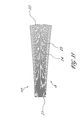
- FIG. 21A is a perspective view of one embodiment of a mixer that comprises an input face, an output face, and ridges that decrease in height (as measured from the valleys) from the input face to the output face.
- FIG. 21B is a perspective view of one embodiment of a mixer that comprises an input face, an output face, and ridges that increase in height from the input face to the output face.
- FIG. 21C is a perspective view of one embodiment of a mixer that comprises an input face, an output face, and ridges that increase in height from the input face and the output face to the center of the mixer.
- FIG. 21D is a perspective view of one embodiment of a mixer that comprises an input face, an output face, and ridges that decrease in height from the input face and the output face to the center of the mixer.
- FIG. 22A is a cross-sectional view of one embodiment of a rippled sidewall comprising ridges that have rounded vertices and valleys that have sharp vertices.
- FIG. 22B is a cross-sectional view of one embodiment of a rippled sidewall comprising ridges that have sharp vertices and valleys that have rounded vertices.
- FIG. 22C is a cross-sectional view of one embodiment of a rippled sidewall comprising ridges and valleys that are highly rounded.
- FIG. 22E is a cross-sectional view of one embodiment of a rippled sidewall comprising ridges that have variable heights.
- FIG. 22G is a cross-sectional view of one embodiment of a rippled sidewall comprising ridges that are separated by a large gap.
- FIG. 22I is a cross-sectional view of one embodiment of a rippled sidewall comprising ridges and valleys that are also rippled.
- FIG. 23B is a cross-sectional view of one embodiment of a rippled sidewall comprising ridges and valleys with sharp vertices and planar faceted surfaces therebetween that approximate the rippled sidewall of FIG. 23A .
- FIG. 23C is a cross-sectional view of one embodiment of a rippled sidewall comprising ridges and valleys having sharp vertices and planar faceted surfaces therebetween that approximate rounded valleys.
- FIG. 25A is a top plan view of one embodiment of a rippled mixer that comprises ridges and valleys that are oriented at an angle ⁇ with respect to the length of the mixer.
- FIG. 25B is a perspective view of one embodiment of a rippled mixer that comprises ridges and valleys that are oriented at an angle ⁇ with respect to the length of the mixer.
- FIG. 25E is a perspective view of one embodiment of a composite mixer that is formed by combining the rippled mixers of FIGS. 25B and 25D .
- FIG. 26A is a perspective view of one embodiment of a composite rippled mixer that is formed by combining a portion of a circular angular-to-area converting mixer that has ridges and valleys that are rotated by an angle, ⁇ , with respect to the length of the circular mixer with a portion of a square angle-to-area converting mixer that has ridges and valleys that are rotated by an angle, ⁇ , with respect to the length of the square mixer.
- FIG. 26B is a plan view of the mixer of FIG. 26A .
- FIG. 28 is a perspective view of one embodiment of a solid mixer that comprises a reflective coating at an input end.
- FIG. 29A is a side elevation view of one embodiment of a mixer comprising ridges and valleys coupled with one embodiment of a projection lens.
- FIG. 29B is a cross-sectional view of one embodiment of a mixer comprising ridges and valleys coupled with one embodiment of a total internal reflection (TIR) collimator.
- TIR total internal reflection
- FIG. 30A is a side elevation view of one embodiment of an optical system comprising a rippled mixer and a projection lens.
- FIG. 30B is a side elevation view of one embodiment of a zoom system formed from the optical system shown in FIG. 30A and a diffuser having a hole therein between the rippled mixer and the projection lens.
- FIG. 30C is a side elevation view of one embodiment of an optical system comprising a rippled mixer, an output lens, and a projection lens.
- FIG. 30D is a side elevation view of one embodiment of the optical system of FIG. 30C with the projection lens spaced away from the output lens to create a “spot” beam pattern.
- FIG. 30E is a side elevation view of one embodiment of the optical system of FIG. 30C with the projection lens in proximity to the output lens to create a “flood” beam pattern.
- FIG. 31 is a schematic illustration of one embodiment of a fiber illuminator that comprises ridges and valleys.
- FIG. 32A is a perspective view of one embodiment of a mixer comprising bends.
- FIG. 32B is a plot of the illuminance distribution at an output face of the mixer of FIG. 32A that results when a relatively small light source is coupled with an input face of the mixer.
- FIG. 32C is a plot of the illuminance distribution at the output face of the mixer of FIG. 32A that results when a relatively large light source is coupled with the input face of the mixer.
- FIG. 32D is a perspective view of one embodiment of a mixer comprising bends and rippled sidewalls having ridges and valleys.
- FIG. 32E is a plot of the illuminance distribution at an output face of the mixer of FIG. 32D that results when a relatively small light source is coupled with an input face of the mixer.
- FIG. 32F is a plot of the illuminance distribution at the output face of the mixer of FIG. 32D that results when a relatively large light source is coupled with the input face of the mixer.
- FIG. 33A is a side elevation view of one embodiment of a mixer that comprises a rippled sidewall coupled with two nonimaging optical elements and a light source.
- FIG. 33B is a side elevation view of one embodiment of a mixer that comprises a rippled sidewall and two bends and is coupled with two nonimaging optical elements and a light source.
- FIG. 33C is a side elevation view of one embodiment of a mixer that comprises a rippled sidewall and four bends and is coupled with two nonimaging optical elements and a light source.
- FIG. 34A is a top plan view of one embodiment of a curved mixer comprising a rippled sidewall.
- FIG. 34B is a top plan view of one embodiment of a curved mixer comprising a rippled sidewall and two tapered ends.
- FIG. 35 is a side elevation view of one embodiment of a mixer that comprises rippled sidewalls and a curved output face.
- FIG. 36A is a cross-sectional view of one embodiment of a mixer that comprises a solid rod and a film comprising ridges and valleys.
- FIG. 36B is a cross-sectional view of one embodiment of a mixer that comprises a hollow tube and an insert comprising ridges and valleys.
- FIG. 37 is a cross-sectional view of one embodiment of a mixer comprising a rod and a hologram.
- FIG. 38A is a front plan view showing one embodiment of a circular mixer comprising a substantially optically transmissive outer layer having an index of refraction that varies around the perimeter of the mixer
- FIG. 38B is a front plan view showing one embodiment of a square mixer comprising a substantially optically transmissive outer layer having an index of refraction that varies around the perimeter of the mixer.
- FIG. 39A is a cross-sectional view of one embodiment of a mixer comprising a core and clad that varies in thickness relative to a surface of the core.
- FIG. 39B is a cross-sectional view of one embodiment of a mixer comprising a core and clad comprising a substantially constant thickness relative to a surface of the core.
- FIG. 40 schematically illustrates a partial perspective view of one embodiment of a rippled sidewall from which a collimated beam of light is reflected into a semicircular distribution pattern.
- FIG. 41A is a partial cross-sectional view of one embodiment of a sidewall comprising ridges and valleys having highly rounded vertices with sloping surfaces therebetween.
- FIG. 41B is a plot of the illuminance distribution obtained by reflecting a beam of collimated light from the sidewall of FIG. 41A .
- FIG. 41C is a partial cross-sectional view of one embodiment of a sidewall comprising ridges having pointed vertices, valleys having rounded vertices, and sloping surfaces therebetween.
- FIG. 41D is a plot of the illuminance distribution obtained by reflecting a beam of collimated light from the sidewall of FIG. 41C .
- FIG. 41E is a partial cross-sectional view of one embodiment of a sidewall comprising ridges having vertices that are more pointed than those shown in FIG. 41C , valleys having vertices that are more gently rounded than those shown in FIG. 41C , and sloping surfaces therebetween.
- FIG. 41F is a plot of the illuminance distribution obtained by reflecting a beam of collimated light from the sidewall of FIG. 41E .
- FIG. 42 is a schematic illustration of a system comprising two rippled mixers coupled with each other via transfer optics.
- FIG. 43 is a schematic illustration of one embodiment of a rippled mixer coupled with a diffuser.
- FIG. 44A is a schematic illustration of a top plan view of one embodiment of a mixer array comprising a plurality of rippled mixers.
- FIG. 44B is a schematic illustration of a side elevation view of the mixer array of FIG. 44A .
- illuminance distributions from light sources, such as light emitting diodes (LEDs), that produce non-uniform illuminance distributions.
- LEDs light emitting diodes
- One known method of achieving this goal employs mixing rods.
- flux from a light source is transferred to an input end of a mixing rod.
- the flux propagates through the mixing rod, typically reflecting from the sidewalls of the mixing rod one or more times.
- coupling a light source that produces a non-uniform illuminance distribution with the input end of the mixing rod produces a substantially uniform illuminance distribution at an output end of the mixing rod.
- Certain mixing rod configurations are particularly effective in achieving substantially uniform illuminance distributions.
- straight rods having rectangular or hexagonal cross-sections are known to work well. Such configurations produce rectangular and hexagonal beam patterns, respectively.
- circular beam patterns are preferred in many applications, such as flashlights, spotlights, fiber illuminators, and projection systems with circular pupils.
- circular straight rods generally provide inferior spatial mixing as compared with rectangular or other faceted configurations.
- hexagonal mixing rods are often used in place of circular mixing rods in order to approximate a circular beam pattern while achieving the advantages of a mixing rod having planar sidewalls. Consequently, there is a need for mixing rods that produce circular beam patterns that have substantially uniform illuminance distributions.
- mixing rod configurations have various limitations. For example, even when the illuminance distribution at the output face of a mixing rod is substantially uniform, the distribution obtained by performing a virtual defocus of the light exiting the mixing rod back to the input face has non-uniformities. Similar non-uniformities exist in the angular distribution of the light exiting the mixing rod.
- the input face of the mixing rod is often approximately conjugate to the pupil of the relay optics.
- the light distribution produced at the pupil plane generally contains a non-uniform illuminance distribution. This distribution may comprise multiple images of the light source, producing a regular pattern of bright and dark regions.
- the performance of square, hexagonal, and other known configurations of effective mixing rods tends to degrade as the length of the mixing rods is decreased.
- uniformity of the kaleidoscope illuminance distribution from a mixing rod tends to diminish with decreasing length because fewer images of the non-uniform illuminance distribution at the input face are obtained.
- shorter mixing rods generally become increasingly sensitive to alignment of a light source with the input face. This phenomenon is particularly disadvantageous for systems that couple multiple LEDs with mixing rods.
- some systems situate red, green, and blue LEDs at the input face of a mixing rod in order to produce white light. Because the LEDs are generally offset from a center point of the input face, the uniformity of the distribution of red, green, and blue light and the quality of the white light produced by the systems decreases as the mixing rod becomes shorter.
- Certain embodiments disclosed herein reduce or eliminate the above-noted problems.
- providing ridges and valleys along an exterior or interior perimeter of a mixing rod substantially improves the performance of the mixing rod.
- Other advantageous embodiments are also disclosed.
- FIG. 1 schematically illustrates a light source 10 coupled with a mixer 20 .
- the mixer 20 comprises an input face 21 , an output face 22 , and a central region 23 extending between the input face 21 and the output face 22 .
- the light source 10 can comprise any suitable light-producing device, such as one or more fluorescent lamps, halogen lamps, incandescent lamps, discharge lamps, light emitting diodes, or laser diodes.
- the light source 10 comprises the output of one or more fiber optic lines.
- the light source 10 is configured to generate multi-chromatic light (e.g., white light), while in other embodiments the light source 10 is capable of generating substantially monochromatic light at one or more selected wavelengths.
- the light source 10 can produce coherent or incoherent light. Other forms of light-producing devices can also be used.
- the light source 10 comprises a combination of light-producing devices.
- the light source 10 comprises a plurality of different color LEDs.
- the light source 10 comprises an array of red, green, and blue LEDs (an “RGB LED array”).
- the light source 10 comprises one or more phosphor LEDs or LEDs (e.g., UV LEDs) with a phosphor.
- phosphors can be used to convert the LED output to a more desired wavelength such as blue to yellow (using e.g., YAG).
- the mixer 20 can have a variety of configurations.
- the mixer 20 comprises a light pipe.
- the mixer 20 comprises a hollow tube with one or more sidewalls. Accordingly, in some instances, a surface of the mixer 20 is lined with a substantially reflective film, coated with a substantially reflective material, or otherwise configured to reflect a substantial portion of light incident thereon.
- a surface of the mixer 20 is lined with a substantially reflective film comprising metal or a dielectric multilayer coating. Other reflective coatings such as paint or pigment, e.g., diffuse white paint, may also be used. Still other arrangements for increasing the reflectivity of surfaces of the mixer 20 may also be used.
- the hollow tube and accordingly the mixer is rigid, and in other embodiments, the hollow tube is flexible.
- the mixer 20 comprises a solid light conduit.
- the mixer 20 comprises a substantially optically transmissive material, such as glass or plastic or some other polymeric material. Other materials may also be used.
- the material is rigid, and in other embodiments, the material is flexible.
- Light may propagate within the mixer 20 being reflected one or more times from the interface between the optically transmissive material and ambient medium, e.g., air, as a result of total internal reflection.
- reflections within solid light conduits have smaller absorption losses than do reflections within hollow light conduits having reflective sidewalls. In certain embodiments, solid light conduits are thus more advantageous.
- the angle of light from the light source 10 is reduced when coupled into the solid mixer 20 as a result of refraction. Accordingly, some solid mixers 20 are longer than similarly sized and dimensioned hollow mixers 20 in order to achieve similar levels of mixing. In some instances, solid mixers 20 attenuate less energy than do hollow, reflective mixers 20 , and are therefore advantageous for certain applications.
- a longitudinal or optical axis 13 extends through the mixer 20 from the input surface 21 to the output surface 22 .
- the optical axis 13 shown in FIG. 1 is parallel to the z-axis.
- the mixer 20 is linear, although the mixer may bend and have different shapes as discussed more fully below.
- the mixer 20 comprises a cylinder.
- the cross-sectional shape and area of the mixer 20 are constant along the full length of the mixer, as measured along the optical axis 13 or z axis.
- the input face 21 and the output face 22 are the same shape and size.
- the cross-sectional shape and/or area of the mixer 20 varies along the length thereof, as measured along the z axis.
- the input face 21 and the output face 22 may vary with respect to each other in shape and/or size.
- the input face 21 defines a rectangle or square and the output face 22 defines a circle or vice versa. Other arrangements are also possible.
- the mixer 20 can have a wide variety of lengths.
- the length of the mixer 20 is larger than a width thereof (e.g., a measurement along the orthogonal x or y axis).
- the length-to-width ratio for a mixer 20 that comprises a hollow tube is about 11:1 or less, about 10:1 or less, 9:1 or less, about 8:1 or less, about 7:1 or less, about 6:1 or less, about 5:1 or less, about 4:1 or less, or about 3:1 or less.
- FIG. 2 schematically illustrates the light source 10 coupled with the mixer 20 via a reflector 12 .
- the reflector 12 is an elliptical collector having an ellipsoidally shaped reflective surface.
- the light source 10 can be located at one focus of the reflector 12 , and an input face 21 of the mixer 20 can be located at the other focus of the reflector 12 .
- the reflector 12 can assume a variety of other shapes and configurations. Additional reflective devices or other optical elements (e.g., lenses, diffractive elements, etc.) can be used to couple the light source 10 with the mixer 20 . In certain configurations, no optical element is used.
- the light source 10 is placed at or adjacent to the input face 21 of the mixer 20 . Numerous other devices and methods can be employed to couple the light source 10 with the mixer 20 .
- FIG. 3 schematically illustrates one embodiment of a mixer 120 comprising a rippled sidewall 15 .
- the rippled sidewall 15 is substantially curved and, in some embodiments, can form a cylinder.
- the mixer 120 comprises a right circular cylinder.
- light propagating within the mixer 120 is reflected more times than it would be within a mixer that has the same dimensions as the mixer 120 but does not have rippled sidewalls.
- the mixer 120 outputs a substantially circular beam at the output face 22 .
- the rippled sidewall 15 comprises a plurality of elongate ridges 24 and valleys 25 that extend along the length of the mixer.
- the mixer 120 comprises a solid light conduit.
- the mixer 120 has a length, as measured along the z axis (defined in FIG. 3 ), ten times greater than its diameter, as measured in the xy plane (defined in FIG. 3 ).
- the ridges 24 and the valleys 25 extend from the input face 21 to the output face 22 of the mixer 120 along the central region thereof 23 .
- Each of the ridges 24 and the valleys 25 has a constant height along the length of the mixer 120 .
- the ridges 24 and the valleys 25 run parallel to the length of the mixer 120 .
- numerous other configurations of the ridges 24 and the valleys 25 are possible. Accordingly, discussion of the illustrated embodiment is for illustrative purposes only, and should not be construed as limiting.
- FIG. 4 schematically illustrates a cross-sectional view of the mixer 120 orthogonal to the optical axis 13 or z-direction.
- the rippled sidewall 15 comprises ridges 24 and the valleys 25 around the full perimeter of the mixer 120 .
- the mixer 120 comprises thirty-two ridges 24 and thirty-two valleys 25 .
- Sixteen of the ridges 24 are formed by two substantially flat sloping surfaces 26 that meet at a vertex.
- the other sixteen ridges 24 are formed by curved sloping surfaces 26 that meet at a vertex.
- the two varieties of the ridges 24 alternate around the perimeter of the mixer 120 , e.g., each ridge 24 of one variety is between two ridges 24 of the other variety
- the height-to-width ratio is greater than about 1:500, greater than about 1:300, greater than about 1:250, greater than about 1:200, greater than about 1:150, or greater than about 1:100. In some embodiments, the height-to-width ratio is less than about 1:100, less than about 1:150, less than about 1:200, less than about 1:250, less than about 1:300, or less than about 1:500.
- the ridge-width-to-mixer-width ratio is greater than about 1:100, greater than about 1:50, or greater than about 1:30. In some embodiments, the ridge-width-to-mixer-width ratio is less than about 1:30, less than about 1:50, or less than about 1:100. In some embodiments, the ridges 24 have an average spacing of between about 1 percent and about 30 percent of the width of the mixer 120 .
- the mixer 120 can comprise more or fewer ridges 24 and valleys 25 , and numerous heights, widths, and configurations of the ridges 24 and valleys 25 are possible.
- Light input into the input face 21 propagates along an optical path down the mixer through the central region 23 between the input face and the output face 22 . Much of this light is reflected from the ribbed sidewalls and in particular reflects from the sloping surfaces forming the ridges 24 and valleys 25 . This light reflects from the sloping surfaces is redirected at a different azimuthal direction toward the output end thereby mixing said light at the output end.
- FIGS. 5A-5F demonstrate that circular mixers having rippled sidewalls 15 , such as the mixer 120 depicted in FIGS. 3 and 4 , can be effective in creating a substantially uniform illuminance distribution at an output face thereof.
- FIGS. 5A-5F corresponds with an arrangement such as that schematically depicted in FIG. 2 , wherein the reflector 12 is an elliptical collector, the light source 10 is located at one focus of the reflector 12 , and the center of the input face 21 is located at the other focus of the reflector 12 , and wherein two distinct mixers are used separately for purposes of comparison, as detailed below.
- FIGS. 5A and 5B illustrate the illuminance distribution at the input face 21 of a mixer.
- FIG. 5A is a spatial plot representing illuminance values at the input face 21
- FIG. 5B is a histogram of each illuminance value measured over the surface of the input face 21 .
- a shading scale corresponding with both FIGS. 5A and 5B is shown along the left-hand side of the histogram of FIG. 5B .
- the shading scale generally indicates that the lowest intensities are shaded the darkest and the highest intensities are shaded the brightest, although the gradation between these two extremes is not uniform.
- FIG. 5A illustrates that the illuminance distribution at the input face 21 is non-uniform.
- the shaded spatial plot indicates that light intensity is high toward the center of the input face 21 and drops off toward the edges of the circular perimeter of the mixer.
- FIG. 5B also indicates that the illuminance distribution of the input face 21 is non-uniform due to the large range of illuminance values that are present in the histogram.
- the plots shown in FIGS. 5C and 5D depict the illuminance distribution at the output face 22 of a smooth circular mixing rod (not shown).
- the plots are of the same variety described with respect to FIGS. 5A and 5B , respectively.
- the mixing rod has a circular cross-section orthogonal to the optical axis or longitudinal (z) direction and a length-to-diameter ratio of about 10:1. This length-to-diameter ratio is useful for comparing the performance of the smooth circular mixing rod with that of a smooth mixing rod having a square cross-section orthogonal to the optical axis or z axis.
- the plots shown in FIGS. 5E and 5F are of the same variety described with respect to FIGS. 5A and 5B , respectively, but correspond to the output of the rippled mixer 120 shown in FIGS. 3 and 4 , which comprises a rippled sidewall 15 .
- the rippled mixer 120 has a length-to-diameter ratio of about 10:1. Accordingly, the only difference between the smooth circular mixing rod associated with FIGS. 5C and 5D and the rippled mixer 120 associated with FIGS. 5E and 5F is the ridges 24 and the valleys 25 disposed around the mixer 120 .
- FIGS. 5E and 5F depict the illuminance distribution at the output face 22 of the rippled mixer 120 .
- the illuminance distribution is substantially uniform.
- FIG. 5E demonstrates that the illuminance is fairly constant over the entire face 22
- FIG. 5F comprises a much narrower and more concentrated range of illuminance values, as compared with FIGS. 5B and 5D .
- FIGS. 5A-5F show that mixers comprising rippled sidewalls are able to create circular beam patterns having substantially uniform spatial illuminance distributions at the output face.
- rippled sidewalls improve the uniformity of the angular distribution of light exiting the output face.
- rippled sidewalls improve uniformity of the color of the light at the output face. Accordingly, the foregoing and following discussion with respect to spatial illuminance distributions of rippled mixers is, in many embodiments, applicable to the angular and/or color distributions of the mixers.
- a circular rippled mixer such as the mixer 120 can be used directly with a round bundle of fibers to provide each fiber within the bundle substantially the same flux density.
- FIGS. 6A-6F demonstrate that mixers having rippled sidewalls 15 can also reduce alignment sensitivity of the light source 10 with the input face 21 .
- FIGS. 6A-6F corresponds with an arrangement similar to that schematically depicted in FIG. 2 , wherein the center of the input face 21 is located at one focus of the reflector, and two distinct mixers are used separately for purposes of comparison, as detailed below; however, the light source 10 is shifted upward (i.e., along they axis in the positive direction) within the reflector 12 and thus away from the other focus of the reflector.
- FIGS. 6C and 6D depict the illuminance distribution at the output face 22 of the smooth circular mixing rod. As shown, the illuminance distribution is non-uniform, and is not much improved over the illuminance distribution shown in FIGS. 6A and 6B .
- FIGS. 6E and 6F depict the illuminance distribution at the output face 22 of the mixer 120 . As shown, the illuminance distribution is substantially uniform. FIG. 6E demonstrates that the illuminance is fairly constant over the entire face 22 , and FIG. 6F demonstrates a much narrower and more concentrated range of illuminance values, as compared with FIGS. 6B and 6D . Furthermore, comparison of FIGS. 6E and 6F with FIGS. 5E and 5F reveals that performance of the mixer 120 is relatively unaffected by the shifted alignment of the light source 10 with respect to the input face 21 . Accordingly, providing mixers with rippled sidewalls can reduce alignment sensitivity of the mixers, which can increase the design and manufacturing tolerances and result in more robust designs.
- FIGS. 7A and 7B schematically illustrate two of many varieties of cross-sectional configurations of ripple sidewalls. Additional varieties are discussed in more detail below.
- FIG. 7A schematically illustrates one cross-sectional configuration of a rippled sidewall 15 comprising a plurality of ridges 24 and valleys 25 .
- Half of the ridges 24 resemble those shown in FIG. 4 , as each is formed by two substantially planar sloping surfaces 26 that meet at a vertex.
- Rippled sidewalls 15 comprising substantially flat surfaces are referred to herein as “faceted.”
- ridges 24 and valleys 25 can be fairly complimentary to each other in some instances, thus the general shape of some rippled sidewalls 15 can be described in terms of ridges 24 alone. Accordingly, references to ridges 24 only are occasionally made herein when describing the general shape of certain rippled sidewalls 15 . However, such references should not be construed as limiting the principles and/or embodiments described herein to those instances where ridges 24 and valleys 25 are complimentary.
- each ridge 24 can be described in terms of an angle ⁇ defined by the sloping face 26 on either side of the ridge 24 and a line 27 extending between the vertices of the two closest valleys 25 on either side of the ridge 24 .
- the valleys 25 can similarly be described in terms of an angle ⁇ . Accordingly, the angle ⁇ depends on the spacing and height of the ridges 24 or the valleys 25 . For example, higher ridges 24 or closer spacing result in larger angle ⁇ .
- each ridge 24 is symmetrical. As detailed below, other configurations are possible for faceted rippled sidewalls 15 .
- the ridges 24 and/or valleys 25 of the rippled sidewalls 15 are not symmetrical and/or are formed by more than two substantially flat faces defining a ridge or valley.
- the angle ⁇ is between about 15 degrees and about 65 degrees. In other embodiments, the angle ⁇ is between about 15 degrees and about 35 degrees or between about 10 degrees and about 25 degrees. Other ranges and values are possible.
- the ridges 24 or valleys 25 can be described in terms of a vertex angle ⁇ defined by the angle between two substantially planar sloping faces 26 .
- the angle ⁇ is between about 15 degrees and about 65 degrees. Other ranges and values are possible.
- FIG. 7B schematically illustrates one cross-sectional configuration of a rippled sidewall 15 comprising ridges 24 and valleys 25 having rounded or curved vertices.
- the angle ⁇ can also generally describe an average angle of the ridges 24 or the valleys 25 .
- the angle ⁇ is defined by the line 27 extending between the vertices of the two valleys 25 neighboring the ridge 24 and by a tangent line 28 extending between a vertex of a neighboring valley 25 and the vertex of the ridge 24 .
- numerous configurations are possible for rounded ridges 24 .
- the ridges can be highly rounded, ellipsoidal, circular, parabolic, any combination thereof, or have any other curved shape.
- the angle ⁇ is between about 20 degrees and about 65 degrees, between about 20 degrees and about 37 degrees, or between about 27 degrees and about 33 degrees.
- the slope and curvature of the surfaces 26 forming the ridges 24 (and valleys) can affect the performance of the mixer 20 .
- the angle ⁇ is generally associated with ridges 24 such as those shown in the illustrated embodiment.
- the angle ⁇ is defined in terms of the height dH of the ridges 24 and the distance dC between successive ridges 24 .
- increasing or decreasing the number of ridges and valleys disposed around a mixer and thereby changing the distance dC, while adjusting the parameters dH such that a remains constant in the above equation can often result in similar performances between the original mixer and the modified mixer.
- the number of ridges 24 disposed around a mixer affects the performance of the mixer. In certain embodiments, the number of ridges 24 is greater than 16. In other embodiments, the number of ridges 24 is greater than 50. In various other embodiments, the number of ridges 24 is greater than 100, 150, 200, 250, 300, 400, 500, 1000, 2000, 3000, or 4000. In some embodiments, the number of ridges 24 is greater than 5000.
- FIG. 8A schematically illustrates one embodiment of a mixer 130 coupled with the light source 10 .
- the mixer 130 comprises a hollow tube that defines a generally cylindrical shape having a circular cross-section orthogonal to the optical axis (z-axis) therethrough.
- the hollow tube has a reflective coating or film covering its interior surface.
- the mixer 130 has a length-to-diameter ratio of about 6:1.
- the mixer 130 further comprises a rippled sidewall 15 having 128 ridges 24 , as schematically illustrated in FIG. 8B .
- the ridges 24 are formed by planar sloping surfaces (as shown), and in another configuration the ridges 24 have rounded vertices and are formed by curved surfaces.
- the light source 10 is disposed at the center of the input face 21 .
- the light source 10 has a diameter that is one fifth the diameter of the input face 21 .
- FIG. 8C is a plot of the intensity distribution of the light source 10 of the illustrated embodiment.
- the light source 10 comprises a Lambertian source that is clipped such that the angular distribution for angles below about 9 degrees and above about 30 degrees is zero.
- the light source 10 simulates the effect of a reflector that has a hole therein, such as can be found in certain flashlight configurations, and/or simulates the effect of the blockage caused by the light source itself being disposed within a reflector.
- blocking low-angle rays removes light having a nearly uniform angular distribution that would otherwise pass through the mixer 20 without interacting with the sidewalls thereof, and thus may have only a small effect on the illuminance distribution at an output face 22 of the mixer 20 .
- the plot further comprises three illustrative points 142 - 144 that correspond with FIGS. 10A and 10B , FIGS. 10C and 10D , and FIGS. 10E and 10F , respectively.
- the angle ⁇ is 0 degrees.
- the point 142 corresponds with a mixer 130 that does not comprise rippled sidewalls, and thus corresponds with a smooth circular mixing rod. Consequently, standard deviation values lower than the value at the point 142 represent illuminance distributions having greater uniformity than that produced by the smooth mixing rod. Conversely, higher standard deviation values represent less uniform illuminance distributions than that produced by the smooth circular mixing rod.
- the performance of the mixer 130 having sharp ridges 24 changes significantly with varying values of ⁇ .
- Rippled sidewalls 15 characterized by an angle ⁇ of about 45 degrees actually yield a less uniform illuminance distribution at the output face 22 than is obtained with a smooth circular mixing rod.
- the mixer 20 having rounded ridges 24 is less sensitive to changing values of ⁇ .
- FIGS. 10A and 10B correspond with the point 142 .
- FIG. 10A is a spatial plot representing illuminance values at the output face 22 . As shown, the intensity is highest at the center of the output face 22 and drops off towards the edges thereof.
- FIG. 10B is a plot representing the kaleidoscope illuminance distribution obtained by defocusing the light exiting the mixer 130 back to the input face 21 of the mixer. As shown in FIG. 10B , the kaleidoscope illuminance distribution is highly non-uniform and contains multiple bright and dark regions caused by multiple images of the light source 10 .
- FIGS. 10C and 10D correspond with the point 143 , which represents the lowest standard deviation value obtained with either of the mixers 130 , and hence represents the most uniform illuminance distribution. It is noted that the rippled circular mixer 130 having rounded ridges 24 produced the value at the point 143 .
- FIG. 10C is a spatial plot representing illuminance values at the output face 22 . As shown, the intensity is substantially uniform over the entire output face 22 .
- FIG. 10D is a plot representing the kaleidoscope illuminance distribution of the mixer 130 , which is much more uniform than that shown in FIG. 10B . In FIG. 10D , images of the light source 10 are substantially smeared, almost to the point of being indistinguishable from each other. Accordingly, mixers having rippled sidewalls 15 can dramatically improve the uniformity of kaleidoscope illuminance distributions.
- FIGS. 10E and 10F correspond with the point 144 , which represents the highest standard deviation value obtained with either of the mixers 130 , and hence represents the least uniform illuminance distribution. It is noted that the rippled circular mixer 130 having sharp ridges 24 formed by substantially flat surfaces and an angle ⁇ of about 45 degrees produced the value at the point 144 . In some embodiments, mixers having sharp ridges 24 characterized by an angle ⁇ of about 45 degrees act much like retroreflecting prisms.
- light incident on a ridge 24 is reflected from two surfaces of the ridge 24 such that light leaving the ridge 24 propagates along a path parallel to the path traced by the incident light, as viewed along the optical axis (e.g., the z axis defined in FIGS. 8 A and 10 A- 10 E) of the mixer 130 .
- the optical axis e.g., the z axis defined in FIGS. 8 A and 10 A- 10 E
- FIG. 10E is a spatial plot representing illuminance values at the output face 22 . As shown, the intensity is highest at the center of the output face 22 and drops off towards the edges thereof. The illuminance distribution is even more peaked than that shown in FIG. 10A .
- FIG. 10F is a plot representing the kaleidoscope illuminance distribution of the mixer 130 , which resembles the distribution shown in FIG. 10B .
- improved kaleidoscope illuminance is achieved with a diffuser at the output face of the mixer.
- the diffuser is a low angle diffuser.
- the diffuser is configured to diffuse collimated light incident perpendicular to the diffuser into an angular distribution having a full-width half-maximum (FWHM) of about 30 degrees or less, about 6 degrees or less, or about 3 degrees or less. Other diffuser angles and diffuser distributions are also possible.
- the FWHM is approximately equal to the angular size of the input face of the mixer, as seen from the output face of the mixer.
- the FWHM follows the equation: FWHM ⁇ arctan( D/L ) where “D” is the input size of the mixer and “L” is the length of the mixer.
- a rippled mixing rod having a substantially uniform transverse cross section along a length thereof is coupled with a diffuser.
- the diffuser homogenizes the light that does not hit the sidewalls of the rippled mixer.
- the scatter angle of the diffuser is small compared to the numerical aperture of the flux coupled out of the mixer.
- the diffuser does not significantly increase the numerical aperture of the output light.
- the term “diffuser” is a broad term used in its ordinary sense, and includes, without limitation, randomly textured surfaces and structured textured surfaces, such as lens arrays, holographic diffusers, and bulk scatter in a thin volume. In some embodiments, bulk scatter can be applied throughout the volume of the mixer or a portion thereof.
- a rippled mixer having a solid configuration such as the mixer 120 or the mixer 130 , comprises a rigid material or a flexible material.
- the mixer comprises optical grade acrylic.
- the mixer comprises elongate ridges and valleys that extend along and run parallel to the full length of the mixer.
- the ridges and the valleys have a substantially constant height of about 0.015 millimeters, about 0.017 millimeters, about 0.020 millimeters, or about 0.025 millimeters.
- the height is greater than about 0.015 millimeters, greater than about 0.017 millimeters, greater than about 0.020 millimeters, or greater than about 0.025 millimeters.
- the height is less than about 0.025 millimeters, less than about 0.020 millimeters, less than about 0.017 millimeters, or less than about 0.015 millimeters.
- the mixer comprises an input face and an output face that each has a diameter of about 3.0 millimeters. In other embodiments, the diameter is greater than about 3.0 millimeters.
- the mixer has a length of about 9.0 millimeters, about 25.0 millimeters, or about 100 millimeters. In some embodiments, the mixer has a length greater than about 9.0 millimeters, greater than about 25.0 millimeters, or greater than about 100 millimeters. Other values are also possible.
- a rippled mixer such as the mixer 120 , comprises an optical fiber.
- the fiber has a diameter (or a cross-sectional width) of at least 3.0 millimeters.
- the fiber comprises a core.
- the core has a diameter (or a cross-sectional width) of at least 3.0 millimeters.
- rippled circular mixers and square mixing rods having hollow configurations both provide substantially uniform illuminance distributions when the input light distribution has a numerical aperture of at least about 0.24 and when the length-to-width ratio of the mixer is at least about 12:1, when the numerical aperture is about at least 0.45 and the length-to-width ratio is at least about 6:1, and when the numerical aperture is at least about 0.7 and the length-to-width ratio is at least about 3:1.
- a rippled circular mixer having a solid configuration provides a substantially uniform illuminance distribution at its output face when its input face has a numerical aperture of about 0.5 and when the mixer has a length-to-width ratio of about 10:1. In some embodiments, similar results can be achieved when the numerical aperture is about 1.0 and the length-to-width ratio is about 3:1. In many embodiments, substantially uniform illuminance distributions can be achieved as the numerical aperture of a mixing rod is increased and the length-to-width ratio thereof is reduced.
- Shorter mixers are also able to provide excellent uniformity, but the general trend is that shorter lengths become increasingly sensitive to the light distribution at the input face 21 . Nevertheless, the ability of rippled, circular mixers to produce a uniform, circular beam when the length-to-width ratio of the mixers is less than about 6:1 is a particularly advantageous result. Shorter mixers allow systems that are more compact, lighter, and potentially less expensive. Furthermore, in some instances, circular mixers have kaleidoscope illuminance distributions that are more uniform than those produced by square mixing rods.
- FIG. 11 schematically illustrates the cross-section of one embodiment of a rippled square mixer 150 .
- the mixer 150 comprises four rippled sidewalls 15 .
- one or more of the rippled sidewalls 15 are substantially planar.
- the one or more rippled sidewalls 15 form a right rectangular prism or a right square prism.
- light propagating within the mixer 150 is reflected more times than it would be within a mixer that has the same dimensions as the mixer 150 but does not have rippled sidewalls.
- the mixer 150 outputs a substantially rectangular or substantially square beam at the output face 22 .
- the one or more sidewalls 15 comprise a plurality of elongate ridges 24 and valleys 25 .
- the ridges 24 and the valleys 25 extend along the length of the mixer 150 .
- the cross-sectional shape and area of the mixer 150 is constant along the entire length of the mixer 150 .
- the height and width of the mixer 150 are each about 4 millimeters.
- the mixer 150 comprises thirty-two rounded ridges 24 around its perimeter that run parallel to the length of the mixer 150 .
- the vertices of the ridges 24 are spaced from each other by approximately 0.5 millimeters and have a constant height of about 120 microns along the length of the mixer 150 .
- Other sizes, dimensions, and configurations of the mixer 150 are possible.
- FIGS. 12A-12F corresponds with an arrangement such as that schematically depicted in FIG. 2 , wherein the reflector 12 is an elliptical collector, the light source 10 is located at one focus of the reflector 12 , and the center of the input face 21 of a mixer is located at the other focus of the reflector 12 , and wherein two distinct mixers are used separately for purposes of comparison, as detailed below.
- FIG. 12A is a plot of the illuminance distribution at the input face 21 of a mixer in such an arrangement. As with the plot shown in FIG. 5A , the illuminance is highest at the center of the input face 21 , and drops off toward the edges thereof.
- FIGS. 12B and 12C correspond with a smooth mixing rod (not shown) having a square cross-section orthogonal to the optical axis or longitudinal (z) direction.
- the smooth square mixing rod is a solid rod having an index of refraction of about 1.5 and a length-to-width ratio of about 10:1.
- FIG. 12B is a plot illustrating the illuminance distribution at the output face 22 of the smooth square mixing rod. As shown, the illuminance distribution is substantially uniform.
- FIG. 12C is a plot representing the kaleidoscope illuminance distribution obtained by defocusing the light exiting the mixing rod back to the input face 21 of the mixing rod. As shown in FIG. 12C , the kaleidoscope illuminance distribution is highly non-uniform and contains multiple bright and dark regions produced by multiple images of the light source 10 .
- FIGS. 12D and 12E correspond with one embodiment of a rippled mixer similar to the rippled mixer 150 .
- the rippled mixer comprises a solid rod having an index of refraction of about 1.5 and a length-to-width ratio of about 10:1.
- the cross-sectional shape and area of the mixer is constant along the entire length thereof.
- the height and width of the mixer are each about 4 millimeters.
- the mixer comprises 128 rounded ridges 24 around its perimeter (thirty-two ridges per side) that run parallel to the length of the mixer.
- the vertices of the ridges 24 are spaced from each other by approximately 0.125 millimeters and have a constant height of about 30 microns along the length of the mixer.
- the only difference between the smooth square mixing rod associated with FIGS. 12B and 12C and the rippled square mixer associated with FIGS. 12D and 12E is the ridges 24 and the valleys 25 disposed around the rippled mixer.
- FIG. 12D is a plot illustrating the illuminance distribution at the output face 22 of the rippled mixer. As shown, the illuminance distribution is substantially uniform. This is a particularly advantageous and unexpected result. Whereas smooth square mixing rods are known to produce uniform illuminance distributions when the mixing rods are sufficiently long, the common practice has been to avoid rounding the corners of the mixing rods. In general, smooth square mixing rods with rounded corners do not perform as well as smooth square mixing rods with sharp corners. However, the addition of ridges to square mixing rods—even rounded ridges—yields illuminance distributions with uniformities comparable to those obtained with smooth square mixing rods that have sharp corners. Furthermore, various examples described below illustrate that rippled sidewalls can actually provide illuminance distributions having uniformities superior to those provided by smooth square mixing rods.
- FIG. 12E is a plot representing the kaleidoscope illuminance distribution obtained by defocusing the light exiting the rippled square mixer back to the input surface of the mixer.
- the kaleidoscope illuminance distribution is much more uniform than that shown in FIG. 12C , which was obtained with a smooth square mixing rod.
- the images of the light source 10 are rotationally smeared.
- FIG. 12F is a plot of the standard deviation, ⁇ , of the illuminance distribution at the output face 22 of the rippled square mixer as a function of the angle ⁇ .
- the plot comprises a curve 160 representing data obtained when the rippled mixer comprises ridges 24 having sharp vertices formed by planar facets, such as the ridges 24 depicted in FIG. 7A , and a curve 161 representing data obtained when the rippled mixer comprises ridges 24 having rounded vertices formed by curved surfaces, such as the ridges 24 depicted in FIGS. 7B and 11 .
- the rippled mixers correspond with a smooth square mixing rod.
- standard deviation values lower than that at which ⁇ equals 0 degrees represent illuminance distributions having better uniformity than that produced by a smooth square mixing rod. Conversely, higher standard deviation values represent less uniform illuminance distributions than that produced by a smooth square mixing rod.
- the performance of the mixer comprising ridges 24 having sharp vertices formed by planar facets varies significantly with different values of ⁇ , and generally provides less uniform distributions than does a smooth square mixing rod.
- the square mixer with sharp vertices creates the least uniform illuminance distribution at an angle ⁇ of about 45 degrees.
- the mixer having ridges 24 with rounded vertices yields far more consistent results with changing values of ⁇ , and, at an angle ⁇ of about 30 degrees, actually provides more uniform distributions than does a smooth square mixing rod.
- FIG. 13A schematically illustrates one embodiment of a mixer 170 coupled with the light source 10 , which is similar to the arrangement described above with respect to FIG. 8A .
- the mixer 170 comprises a hollow square tube having a substantially reflective coating or film covering its interior surface.
- the mixer 170 has a height of about 2 millimeters, a width of about 2 millimeters, and a length-to-width ratio of about 6:1.
- the mixer 170 comprises ridges 24 having sharp vertices formed by planar facets, and in another embodiment, the mixer 170 comprises ridges 24 having rounded vertices formed by curved surfaces.
- the mixer 170 comprises 128 rounded ridges 24 around its perimeter (thirty-two ridges per side) that run parallel to the length of the mixer.
- the vertices of the ridges 24 are spaced from each other by approximately 0.0625 millimeters and have a constant height along the length of the mixer.
- the light source 10 is approximately at the center of the input face 21 of the mixer 170 and has diameter that is one fifth the width of the input face.
- FIG. 13B is a plot of the intensity distribution of the light source 10 of the illustrated embodiment.
- the light source 10 comprises a Lambertian source similar to that described above with respect to FIG. 8C .
- FIG. 13C is a plot of the standard deviation, ⁇ , of the illuminance distribution at the output face 22 of the mixer 170 of FIG. 13A as a function of the angle ⁇ , and is similar to the plot shown in FIG. 12F .
- the plot comprises a curve 180 representing data obtained when the mixer 170 comprises ridges 24 having sharp vertices formed by planar faces and a curve 181 representing data obtained when the mixer 170 comprises ridges 24 having rounded vertices formed by curved surfaces.
- the angle ⁇ is 0 degrees
- the mixers 170 correspond with a smooth square mixing rod. Accordingly, standard deviation values lower than that at which ⁇ equals 0 degrees represent illuminance distributions having improved uniformity over those produced by a smooth square mixing rod. Conversely, higher standard deviation values represent less uniform illuminance distributions.
- illuminance distributions obtained from the mixer 170 comprising ridges 24 having sharp vertices formed by planar facets vary widely with varying values of ⁇ , and are generally less uniform than those obtained from a smooth square mixing rod. Planar facets with an angle ⁇ between 10 and 25 degrees can provide reasonable uniformity for this example.
- the square mixer 170 comprising ridges 24 with sharp vertices creates the least uniform illuminance distribution at an angle ⁇ of about 45 degrees.
- the square mixer 170 comprising ridges 24 having rounded vertices yields far more consistent results with changing values of ⁇ than does the square mixer 170 comprising ridges 24 with sharp vertices. Also, the square mixer 170 comprising ridges 24 with rounded vertices yields a more uniform illuminance distribution, as compared with a smooth square mixing rod, over a wider range of angles than does the square mixer 150 comprising ridges 24 with rounded vertices described above (with respect to FIG. 12F ).
- Rippled square mixers such as those just described generally have more uniform kaleidoscope illuminance distributions than do non-rippled square mixing rods. Rippled sidewalls tend to rotationally smear images of the non-uniform illuminance distribution of the light source, resulting in a less regular pattern of bright and dark regions. Furthermore, in some cases, rippled sidewalls comprising ridges with rounded vertices improve kaleidoscope illuminance distribution uniformity to a greater extent than do rippled sidewalls comprising ridges with sharp vertices. In certain instances, mixers comprising rippled sidewalls can be shorter than smooth mixers due to the improved kaleidoscope illuminance distributions that result.
- mixers comprising circular and square cross-sections and further comprising rippled sidewalls
- numerous other mixer configurations can benefit from rippled sidewalls.
- Some examples include mixers having rectangular, pentagonal, trapezoidal, cross-shaped cross-sections, although the possible embodiments should not be limited to these.
- mixer configurations having round (e.g., non-faceted) cross-sections particularly benefit from rippled sidewalls, since mixers of this variety often produce highly non-uniform illumination distributions.
- FIGS. 14A-14D demonstrate the improvement in illuminance distribution resulting from adding rippled sidewalls to a smooth mixer having an oval-shaped cross-section.
- FIG. 14A schematically depicts the cross-section of a smooth mixer 191 without rippled sidewalls
- FIG. 14B is a plot of the illuminance distribution at an output face of the mixer 191 .
- FIG. 14C schematically depicts the cross-section of a rippled mixer 192 comprising a rippled sidewall 15 having ridges 24 and valleys 25
- FIG. 14D is a plot of the illuminance distribution at an output face of the rippled mixer 192 .
- the rippled mixer 192 provides a more uniform illuminance distribution than does the smooth mixer 191 .
- the mixer 192 comprises a substantially elliptical cross-section.
- FIG. 15 schematically depicts the cross-section of one embodiment of a rippled mixer 195 comprising rippled sidewalls 15 having ridges 24 and valleys 25 .
- the mixer 20 comprises a first portion 197 that is substantially oval-shaped and a second portion 198 that is substantially pentagonal. Four sides of the pentagon are planar and the fifth side of the pentagon is replaced with the oval portion 197 . Accordingly, the mixer 195 is a composite of faceted and rounded sides and shapes.
- the rippled sidewalls 15 improve the illuminance distribution of the composite mixer 195 . Many composite mixer configurations can have improved illuminance distributions through the inclusion therein of rippled sidewalls 15 .
- FIG. 16A schematically illustrates one embodiment of a mixer 200 having smooth sidewalls and comprising an input face 21 and an output face 22 that have different areas. Accordingly, the cross-sectional area changes along the length of the mixer 200 . In some embodiments, the shape of the cross-section of the mixer 200 also changes along the length of the mixer 200 . In the illustrated embodiment, the input face 21 and the output face 22 are each rectangular, and the area at the input face 21 is smaller than the area at the output face 22 . In certain arrangements, the mixer 200 provides an angle-to-area conversion of the distribution of light entering the input face 21 .
- a change in the cross-sectional area along the length of the mixer 200 causes the angular distribution at the output face 22 to be narrower or wider than the angular distribution at the input face 21 .
- the numerical aperture at the input face 21 may be larger than the numerical aperture at the output 22 end because the area at the input face is smaller than the area at the output face.
- the mixer 200 does not provide uniform illuminance distributions at the output face 22 . This is especially true when the length of the mixer 200 is relatively short.
- FIG. 16C schematically illustrates a mixer 208 comprising an input face 21 and an output face 22 that have different shapes and sizes.
- the input face 21 is oval-shaped, and the output face 22 is rectangular and has a larger area than the input face 22 .
- the mixer includes a central region between the input face 21 and the output face 22 that transforms from an oval cross-section toward the input face to a rectangular cross-section toward the output face.
- the mixer 208 provides input light with an angle-to-area conversion.
- etendue is conserved.
- the mixer 208 comprises rippled sidewalls 15 having ridges 24 and valleys 25 that improve the illuminance distribution at the output face 22 . Numerous other arrangements are possible for the input face 21 , the output face 22 , the central region therebetween, and/or the rippled sidewalls 15 .
- rippled angle-to-area converting mixers such as the mixers 204 , 208 just described, not only permit angle-to-area conversion of input light, but also homogenize the input light, as further discussed below.
- rippled sidewalls are advantageously included in angle-to-area converting mixers that are used to produce white light from RGB LED arrays.
- the rippled sidewalls reduce sensitivity of the mixers to alignment with the light source at the input face.
- the rippled sidewalls can also reduce the length required for the mixers to produce a substantially uniform illuminance distribution, as illustrated by certain embodiments described herein.
- FIG. 17A schematically depicts one embodiment of an angle-to-area converting mixer 210 coupled with the light source 10 .
- the light source 10 can comprise a wide variety of light producing devices.
- the light source 10 comprises an RGB LED array having four sources 221 - 224 disposed in two columns and two rows.
- two of the sources 221 , 222 are green LEDs
- one source 223 is a red LED
- the other source 224 is a blue LED.
- the array comprises one, two, three, four, five, or six rows of LEDs
- the array comprises one, two three, four, five, or six columns of LEDs. Other numbers and combinations of sources are possible for the LED array.
- the array comprises a plurality of rows and/or a plurality of columns of light emitting diodes.
- the LED array comprises one or more phosphor LEDs.
- the sources 221 - 224 are substantially aligned in a plane.
- the sources 221 - 224 are disposed on a common substrate and, in further embodiments, are situated in proximity (e.g., adjacent) to each other.
- the light source 10 comprises any number of LEDs and/or any other suitable light-producing devices.
- the mixer 210 comprises an input face 21 and an output face 22 .
- the input face 21 is substantially square and the output face 22 is substantially circular and has an area larger than the input face 21 .
- the mixer 210 can be symmetrical about two perpendicular axes, such as the x and y axes defined in FIG. 17A . Such arrangements can be particularly suitable for planar RGB LED arrays.
- the mixer 210 can also be symmetrical about one axis only, and in other arrangements, the mixer 210 is asymmetrical.
- the input face 21 is substantially square and has a width between about 1.0 millimeters to about 12 millimeters, between about 0.5 millimeters to about 1.5 millimeters, between about 1.0 millimeters to about 2.0 millimeters, between about 2.0 millimeters to about 3.0 millimeters, or between about 3.0 millimeters to about 4.0 millimeters.
- the width is less than about 2.5 millimeters, less than about 2.0 millimeters, less than about 1.5 millimeters, less than about 1.0 millimeters, less than about 0.5 millimeters, or less than about 0.25 millimeters.
- the width is greater than about 0.25 millimeters, greater than about 0.5 millimeters, greater than about 1.0 millimeters, greater than about 2.0 millimeters, or greater than about 3.0 millimeters. In some arrangements, the width is about 0.5 millimeters, about 1.0 millimeters, about 1.5 millimeters, about 2.0 millimeters, about 2.1 millimeters, about 2.2 millimeters, about 2.5 millimeters, or about 3.0 millimeters.
- the width is about 1.0 centimeters, about 1.5 centimeters, about 2.0 centimeters, about 2.5 centimeters, about 3.0 centimeters, about 5.0 centimeters, or about 10.0 centimeters.
- Other sizes and configurations for the input face 21 are possible.
- the output face 22 is substantially circular and has a diameter of from about 0.5 millimeters to about 3.0 millimeters, from about 1.0 millimeter to about 5.0 millimeters, from about 2.0 millimeters to about 7.0 millimeters, from about 2.5 millimeters to about 6.0 millimeters, or from about 3.0 millimeters to about 5.0 millimeters. In other arrangements, the diameter is less than about 7.0 millimeters, less than about 5.0 millimeters, less than about 2.0 millimeters, less than about 1.0 millimeters, and less than about 0.5 millimeters.
- the length of the mixer 210 is from about 0.1 centimeters to about 10.0 centimeters, from about 0.2 centimeters to about 3.5 centimeters, from about 1.0 centimeters to about 5.0 centimeters, or from about 1.5 centimeters to about 3.0 centimeters. In some embodiments, the length is less than about 10.0 centimeters, less than about 5.0 centimeters, less than about 3.0 centimeters, less than about 1.0 centimeters, or less than about 0.5 centimeters.
- the rippled mixer 230 comprises rippled sidewalls 15 having ridges 24 and valleys 25 .
- the ridges 24 have rounded vertices, and in other embodiments, the ridges have sharp vertices.
- the mixer 20 comprises between about 15 and about 25, between about 35 and about 45, or between about 70 and about 90 ridges 24 .
- the mixer 230 comprises greater than about 15, greater than about 30, greater than about 70, greater than about 100, greater than about 500, greater than about 1000, or greater than about 5000 ridges 24 .
- the mixer 230 comprises about 20, about 40, or about 80 ridges 24 .
- the ridges 24 have a constant height along the length of the mixer 230 .
- the height is from about 5.0 microns to about 50 microns. In some embodiments the height is less than about 50 microns, less than about 40 microns, less than about 30 microns, less than about 20 microns, less than about 10 microns, or less than about 5.0 microns. In other embodiments, the height is greater than about 30 microns, greater than about 40 microns, or greater than about 50 microns. Other heights are possible. In some embodiments, the height is from about 10 to about 100 times larger than the wavelength or wavelengths for which mixing is desired.
- the ridges 24 have a constant angle ⁇ along the length of the mixer 230 .
- the angle ⁇ of the ridges 24 is between about 20 degrees and about 40 degrees, between about 33 degrees and about 37 degrees, between about 53 degrees and about 73 degrees, or between about 60 degrees and about 66 degrees along the length of the mixer 20 .
- the angle ⁇ is about 26 degrees, about 33 degrees, about 35 degrees, or about 63 degrees. Other angles are possible.
- the angle ⁇ of the ridges 24 varies along the length of the mixer 230 .
- the mixer 230 comprises a solid material having an index of refraction of about 1.5.
- the embodiment just described is illustrative and should not be interpreted as limiting. Other configurations are possible.
- the angle ⁇ of the ridges 24 is constant along the length of the mixer 230 and the height of the ridges 24 varies along the length of the mixer 230 .
- each of the sources 221 - 224 produces similar results when separately illuminated. Accordingly, in some embodiments, the mixer 230 produces highly uniform white light when all of the sources 221 - 224 are illuminated simultaneously.
- the circular output face 22 can produce a highly uniform circular beam that can be used in applications such as illuminating a circular bundle of optical fibers. Additional applications include flashlights and other portable lights, spot lights, and projection systems with circular pupils. Other applications are also possible.
- the mixer 230 is relatively insensitive to alignment of the light source 10 with the input face 21 , which permits more robust performance of the mixer 230 .
- the mixer 230 can be easier to manufacture and have greater longevity since it will work well even if the sources 221 - 224 are moved out of alignment due to manufacturing constraints, manufacturing defects, user error, or other factors.
- some arrangements are configured such that fewer than four LEDs are illuminated to produce white light. Accordingly, one or more of the LEDs can serve as a backup in case one of the other LEDs fails. In some embodiments, more than four LEDs are used, and in further embodiments, some of the LEDs serve as dedicated backups.
- the mixer 230 comprises a planar RGB LED array that is positioned adjacent to the input face 21 and that completely fills the area thereof.
- the array covers a smaller area than the input face 21 or comprises fewer LEDs.
- underfilling the input face 21 has little effect on the uniformity of the illuminance distribution at the output face 22 of the mixer 230 .
- light sources other than LEDs are coupled with the input face 21 .
- the light source 10 is coupled with the input face 21 via a reflector, such as the reflector 12 described above. Any other suitable method or device can be used to couple the light source 10 with the mixer 230 .
- the mixer 230 provides substantially uniform distributions when the light source 10 is centered with respect to the input face 21 .
- the mixer 230 comprises ridges 24 with relatively large angles ⁇ , and can achieve comparable levels of uniformity as arrangements wherein the light source 10 is centered. Accordingly, in some embodiments, ridges 24 having larger angles ⁇ can be used to compensate for an off-centered light source.
- FIG. 18A schematically illustrates one embodiment of an angle-to-area converting mixer 240 comprising sidewalls 15 having ridges 24 and valleys 25 .
- the mixer 240 resembles the mixer 230 shown in FIG. 17E in many respects, but can differ in manners such as those now described.
- the mixer 240 comprises a rectangular input face 21 .
- the mixer 210 includes a central region between the input face 21 and the output face 22 that transforms from a rectangular cross-section toward the input face to a circular cross-section toward the output face.
- the area of the cross-sections also increase from the input face 21 through the central region to the output face 22 .
- FIG. 18A schematically illustrates one embodiment of an angle-to-area converting mixer 240 comprising sidewalls 15 having ridges 24 and valleys 25 .
- the mixer 240 resembles the mixer 230 shown in FIG. 17E in many respects, but can differ in manners such as those now described.
- the mixer 240 comprises a rectangular input face
- the shape of the cross-section midway between the input face 21 and the output face 22 includes portions of the circular cross-section and portions of the rectangular cross-section.
- Cross-sections closer to the input face include more of the rectangular cross-section portions and cross-sections closer to the output face include more of the circular cross-section portions.
- the mixer 240 can be coupled with an RGB LED array having four sources 221 - 224 .
- the sources 221 - 224 are aligned in a single column along the input face 21 .
- the plurality of LEDs are arranged in a linear array.
- the array comprises more or fewer LEDs, and can be arranged in multiple columns and rows.
- the mixer 240 comprises a solid, substantially transmissive material having an index of about 1.5.
- the mixer 240 has a length of about 15 millimeters, an output face 22 having a diameter of about 4.7 millimeters, and an input face 21 having a width of about 1.0 millimeter and a height of about 4.2 millimeters.
- the mixer 240 comprises 80 ridges 24 along the full length thereof, each having a constant height of about 0.024 millimeters. When the sources 221 - 224 are all illuminated, the mixer 240 produces white light that is superior to that produced by a mixer without rippled sidewalls of comparable composition and dimensions.
- FIG. 19A schematically illustrates one embodiment of a rippled angle-to-area converting mixer 250 comprising a circular input face 21 and a circular output face 22 .
- the mixer 250 comprises ridges 24 and valleys 25 that have a constant height and extend along the full length of the mixer.
- the mixer is conical in shape, and includes a central region between the input face 21 and the output face 22 . Cross-sections through the central region are also circular. The cross-sections increase in size (e.g., area, diameter, etc.) from the input face 21 to the output face 22 .
- the input face 21 of the mixer 250 has a diameter of about 3.0 millimeters
- the output face 22 has a diameter of about 6.0 millimeters
- the mixer 250 has a length of about 18.0 millimeters.
- the ridges 24 and the valleys 25 vary in height and/or width along the length of the mixer 250 .
- FIG. 19B schematically illustrates one embodiment of a rippled angle-to-area converting mixer 252 comprising a square input face 21 and a square output face 22 .
- mixer 210 includes a central region between the input face 21 and the output face 22 . Cross-sections through the central region are also square. The cross-sections increase in size (e.g., area, width, etc.) from the input face 21 to the output face 22 .
- the circular input face 21 of the mixer 250 has a diameter that is approximately equal to the width of the square input face 21 of the mixer 252
- the circular output face 22 of the mixer 250 has a diameter that is approximately equal to the diagonal measurement of the square output face 22 of the mixer 252 .
- the mixer 252 comprises ridges 24 and valleys 25 that have a constant angle ⁇ and extend along the full length of the mixer.
- the input face 21 of the mixer 252 has a width of about 3.0 millimeters
- the output face 22 has a width of about 4.2 millimeters
- the mixer 252 has a length of about 18.0 millimeters.
- the ridges 24 and the valleys 25 vary in height and/or width along the length of the mixer 252 .
- FIG. 19C schematically illustrates one embodiment of a composite rippled mixer 255 that results when portions of the illustrated embodiments of the mixer 250 and the mixer 252 are combined.
- the composite mixer 255 comprises a square input face 21 that is identical to the input face 22 of the mixer 252 , and comprises a circular output face 22 that is identical to the output face 22 of the mixer 250 .
- the mixer 210 includes a central region between the input face 21 and the output face 22 that transforms from a square cross-section toward the input face to a circular cross-section toward the output face. The area of the cross-sections also increase from the input face 21 through the central region to the output face 22 . In the embodiment shown in FIG.
- the shape of the cross-section midway between the input face 21 and the output face 22 includes portions of the square cross-section and portions of the circular cross-section.
- Cross-sections closer to the input face include more of the square cross-section portions and cross-sections closer to the output face include more of the circular cross-section portions.
- the mixer 255 also comprises ridges 24 and valleys 25 that represent a combination of portions of the respective ridges 24 and valleys 25 of the constituent mixers 250 , 252 .
- each constituent mixer 250 , 252 comprises the same number of ridges 24 and valleys 25 . Accordingly, in some embodiments, the ridges 24 and the valleys 25 of the composite mixer 255 are continuous and extend along the full length of the mixer. In some embodiments, the height of the ridges 24 and the valleys 25 of the composite mixer 255 are constant along the length of the mixer, and in other embodiments, the height changes along the length of the mixer. Similarly, the width of the ridges 24 and the valleys 25 can also remain constant or change along the length of the mixer 255 .
- each constituent mixer 250 , 252 comprises a different number of ridges 24 and valleys 25 .
- the composite mixer 255 can comprise a different number of ridges at the input face 21 and at the output face 22 .
- neither set of ridges 24 and valleys 25 from the constituent mixers 250 , 252 extends along the full length of the mixer. Consequently, in some instances, the height of the ridges 24 and of the valleys 25 of the composite mixer 255 changes along the length of the mixer. Similarly, the width of the ridges 24 and the valleys 25 can also change along the length of the mixer.
- Boolean operations can be used to combine portions of the constituent mixers 250 , 252 into the composite mixer 255 .
- Other operations can also be used to combine portions of the constituent mixers 255 .
- portions of more than two constituent mixers 250 , 252 are combined to form the composite mixer 255 .
- FIG. 20A schematically illustrates one embodiment of a rippled mixer 260 comprising ridges 24 and valleys 25 .
- the mixer 260 resembles the mixer 120 described above with respect to FIGS. 3 and 4 , except that the mixer 260 narrows toward the center thereof.
- a circular input face 21 and a circular output face 22 of the mixer 20 are substantially equally sized.
- FIG. 20B schematically illustrates one embodiment of a rippled mixer 162 comprising ridges 24 and valleys 25 .
- the mixer 262 resembles the square mixers 150 , 170 described above in some respects.
- square input face 21 and a square output face 22 are substantially equally sized, and have a diagonal that is equal to the diameter of the circular input face 21 and the circular output face 22 of the mixer 260 .
- FIG. 20C schematically illustrates one embodiment of a composite rippled mixer 265 that results when portions of the mixer 260 and of the mixer 262 are combined.
- the composite mixer 265 comprises a circular input face 21 and a circular output face 22 that are identical to those of the mixer 260 .
- the shape of the cross-section midway between the input face 21 and the output face 22 includes portions of the square cross-section and portions of the circular cross-section.
- the four corners of the square cross-section of the mixer shown in FIG. 20B are included midway between the input and output faces 21 , 22 .
- Also at the midway location are curved side portions corresponding to portions of the narrowed circular cross-section of the mixer shown in FIG. 20A .
- cross-sections closer to the input face and output faces include more of the circular cross-section portions and less of the square portions.
- the mixer 265 comprises ridges 24 and valleys 25 that represent the combination of portions of the respective ridges 24 and valleys 25 of the constituent mixers 260 , 262 .
- portions of the constituent mixers 260 , 262 are combined via Boolean operations.
- the constituent mixers 260 , 262 are combined via the “union” Boolean operation, such as when the composite mixer 265 comprises the larger profile of the constituent mixers 260 , 262 for each cross section along the length of the mixer 265 .
- the constituent mixers 260 , 262 are combined via the “intersection” Boolean operation.
- FIG. 21A schematically illustrates one embodiment of a rippled mixer 270 comprising ridges 24 and valleys 25 that decrease in height from an input face 21 to an output face 22 .
- the ridges 24 and the valleys 25 do not extend along the full length of the mixer 270 .
- a portion of the mixer 270 near the output face 22 is smooth.
- FIG. 21B schematically illustrates one embodiment of a rippled mixer 272 comprising ridges 24 and valleys 25 that increase in height from an input face 21 to an output face 22 .
- the ridges 24 and the valleys 25 do not extend along the full length of the mixer 272 .
- a portion of the mixer 272 near the input face 22 is smooth.
- the ridges 24 and the valleys 25 have an average length of between about 50 percent and about 100 percent of the length of the mixers 270 , 272 .
- the ridges 24 and the valleys 25 have an average length of between about 0.1 centimeter and about 10 centimeters. Other ranges and values are possible.
- the increase or decrease in height of the ridges 24 and the valleys 25 of the mixers 270 , 272 is linear (e.g., as viewed from a plane parallel to that of the yz plane defined in FIGS. 21A and 21B , wherein the top and/or bottom of either of the mixers 270 , 272 defines a straight line).
- the increase or decrease in the height of the ridges 24 and valleys 25 is nonlinear.
- FIG. 21C schematically illustrates one embodiment of a rippled mixer 274 comprising ridges 24 and valleys 25 that increase in height from both an input face 21 and an output face 22 toward the center of the mixer 274 .
- FIG. 21D schematically illustrates one embodiment of a rippled mixer 276 comprising ridges 24 and valleys 25 that decrease in height from both an input face 21 and an output face 22 toward the center of the mixer 276 .
- the ridges 24 and the valleys 25 increase and decrease in height toward a portion of the mixers 274 , 276 other than the center thereof.
- the ridges 24 and the valleys 25 extend along less than the full length of the mixers 274 , 276 .
- the ridges 24 and the valleys 25 have an average length of between about 50 percent and about 100 percent of the length of the mixers 274 , 276 . In some embodiments, the ridges 24 and the valleys 25 have an average length of between about 0.1 centimeter and about 10 centimeters. Other ranges and values are possible.
- the ridges 24 and the valleys 25 increase and decrease in height multiple times between the input face 21 and the output face 22 .
- the ridges 24 and the valleys 25 increase and decrease in height in a regular pattern along the length of the mixers 274 , 276 .
- the ridges 24 and the valleys 25 undulate along the length of the mixers 274 , 276 in a sinusoidal pattern.
- ridges 24 and valleys 25 that increase and/or decrease in height along a length of a mixer can scatter light incident thereon.
- the width of the ridges 24 and/or the valleys 25 varies in manners similar to those just described. In other embodiments, both the width and the height of the ridges 24 and the valleys 25 vary along the length of the mixers 270 , 272 , 274 , 276 .
- each of the mixers 270 , 272 , 274 , 276 depicted in FIGS. 21A-21D provides a more uniform illuminance distribution at the output face 22 than does a smooth circular mixing rod of equal length and comprising input and output faces of like area.
- ridges and valleys that have constant widths and constant heights are preferred.
- such mixers perform as well as or better than alternative embodiments that comprise ridges and valleys having varying widths and heights.
- mixers having constant ridge and valley widths and heights can be easier to manufacture.
- the height and/or width of the ridges 24 and the valleys 25 can be varied to accommodate an unbalanced or off-centered illuminance distribution at the input face 21 and/or to create a desired illuminance distribution at the output face 22 .
- the ripples are different on different sides of the mixer.
- Such variation may also be useful in dealing with unbalanced or off-centered light sources and illuminance distributions.
- the performance for such arrangements can be determined using illumination simulations with commercially available software tools, such as LightTools®, available from Optical Research Associates of Pasadena, Calif.
- each faceted ridge 24 comprises two substantially planar faces 26 .
- the rounded ridges 24 and rounded valleys 25 have smoothed vertices.
- mixers comprise any alteration and/or combination of faceted and rounded profiles, such as the examples now described.
- FIGS. 22A-22I schematically illustrate the cross-sectional profiles of illustrative embodiments of rippled sidewalls.
- FIG. 22A schematically illustrates one embodiment of a rippled sidewall 15 comprising ridges 24 that have rounded vertices and valleys 25 that have sharp vertices.
- FIG. 22D schematically illustrates one embodiment of a rippled sidewall 15 comprising ridges 24 and valleys 25 having vertices that are connected by splines.
- the profile is sinusoidal.
- the profile is composed of parabolic arcs with ridges 24 and valleys 25 having opposite concavities.
- the profile is composed of a faceted profile, such as the profile illustrated in FIG. 7A , that is smoothed into a rounded shape by using a cubic spline. Other spline profiles are also possible.
- FIG. 22E schematically illustrates one embodiment of a rippled sidewall 15 comprising ridges 24 that have variable heights dH and/or variable angles ⁇ .
- one or more of the ridges 24 comprise substantially planar sloping surfaces 26 that meet at a vertex.
- one or more of the ridges 24 comprise rounded vertices.
- FIG. 22F schematically illustrates one embodiment of a rippled sidewall 15 comprising ridges 24 that have angles ⁇ that vary irregularly or randomly.
- FIG. 22G schematically illustrates one embodiment of a rippled sidewall 15 comprising ridges 24 that are separated by a large gap 282 .
- the result is a duty cycle that is different from 50%.
- FIG. 22H schematically illustrates one embodiment of a rippled sidewall 15 comprising ridges 24 and valleys 25 with sharp vertices connected by planar sloping surfaces as well as ridges 24 and valleys 25 with rounded vertices connected by curved sloping surfaces.
- the ridges 24 and the valleys 25 with sharp vertices and the ridges 24 and the valleys 25 with rounded vertices comprise various heights dH and widths w.
- different ridges 24 and valleys 25 have different heights and widths.
- FIG. 22I schematically illustrates one embodiment of a rippled sidewall 15 comprising ridges 24 and valleys 25 that are rippled.
- ridges 24 such as those illustrated in FIG. 22I comprise one periodic structure with another structure having a smaller period superposed thereon.
- FIG. 23A schematically illustrates the cross-sectional profile of one embodiment of a rippled sidewall 15 comprising ridges 24 with rounded vertices and valleys 25 with sharp vertices and curved surfaces therebetween.
- mixers that comprise ridges 24 with rounded vertices provide more uniform illuminance distributions than do similarly configured mixers that comprise ridges 24 with sharp vertices.
- mixers comprising angled ridges 24 can be easier to manufacture.
- the ridges 24 comprise multiple facets in order to approximate a rounded profile.
- FIG. 23B schematically illustrates the cross-sectional profile of one embodiment of a rippled sidewall 15 comprising ridges 24 and valleys 25 with sharp vertices and planar surfaces therebetween that approximate the rippled sidewall 15 depicted in FIG. 23A . Because these sloping surfaces comprise a plurality of planar portions, these sloping surfaces therefore said to be faceted.
- Each ridge 24 and valley 25 comprises six substantially planar faces or facets 26 (three for each sloping surface), although more or fewer faces or facets could be used.
- FIG. 23C schematically illustrates the cross-sectional profile of one embodiment of a rippled sidewall 15 comprising ridges 24 and valleys 25 having sharp vertices and faceted sloping surfaces therebetween that approximate rounded valleys.
- Each ridge 24 and each valley 25 comprises four substantially planar faces 26 (two on each sloping surface), although more or fewer faces could be used.
- Rippled sidewalls can be configured to produce any one of, or any combination of, substantially uniform, substantially peaked, or substantially dipped illuminance distributions.
- ridges with sharp vertices having planar surfaces that define an angle ⁇ of 45 degrees produce highly non-uniform illuminance distributions that, in many instances, are peaked. This is especially true with certain circular arrangements, as illustrated by the point 144 in FIG. 9 and the plot in FIG. 10E .
- rippled sidewalls comprise sharp ridges having an angle ⁇ of 45 degrees in combination with other ridge forms to control the illuminance distribution at the output face of a mixer.
- FIG. 24 schematically illustrates a cross-sectional view of a portion of one embodiment of a mixer 290 comprising a rippled sidewall 15 having sharp ridges 24 that define an angle ⁇ of about 45 degrees and that are disposed between ridges 24 that have rounded vertices.
- the mixer 290 produces a highly peaked or mildly peaked illuminance distribution, depending on the angle ⁇ used for the sharp ridges 24 .
- FIG. 25A schematically illustrates one embodiment of a mixer 300 comprising a rippled sidewall 15 having elongate ridges 24 and valleys 25 that are oriented at an angle with respect to the length of the mixer.
- the mixer 300 runs substantially parallel with the z axis, as defined by a dashed line in FIG. 25A , and the ridges 24 and the valleys 25 are oriented at a positive angle ⁇ with respect to the z axis.
- the angle ⁇ is less than about 40 degrees, less than about 30 degrees, less than about 20 degrees, less than about 10 degrees, less than about 5 degrees, or less than about 3 degrees. In various other embodiments, the angle ⁇ is between about 5 degrees and about 40 degrees, between about 7.5 degrees and about 30 degrees, or between about 10 degrees and about 30 degrees. Values outside these ranges are also possible. In some embodiments, the angle ⁇ becomes smaller as the number of ridges 24 and valleys 25 increases.
- FIG. 25B schematically illustrates one embodiment of a mixer 305 comprising a rippled sidewall 15 having ridges 24 and valleys 25 that have a small angle ⁇ . The angled ridges 24 and valleys 25 appear to twist about the circular mixer.
- FIG. 25C schematically illustrates one embodiment of a mixer 310 comprising a rippled sidewall 15 having ridges 24 and valleys 25 that are oriented at a negative angle ⁇ with respect to the z axis, as defined by a dashed line in FIG. 25C .
- the absolute value of the angle ⁇ can equal any of the values described above with respect to the angle ⁇ .
- FIG. 25D schematically illustrates one embodiment of a mixer 315 comprising rippled sidewall 15 having ridges 24 that have a small angle ⁇ .
- FIG. 25E schematically illustrates one embodiment of a composite mixer 320 comprising a rippled sidewall 15 having ridges 24 and valleys 25 such as those of the mixer 305 superposed on the ridges 24 and the valleys 25 of the mixer 315 (or vice versa). Accordingly, the composite mixer 320 of FIG. 25E has two sets of ridges 24 and valleys 25 . In some arrangements, small values of the angles ⁇ and ⁇ are preferred in order to avoid etendue increases.
- the ridges 24 and the valleys 25 are oriented at angles ⁇ and ⁇ , and the value of the angle ⁇ plus the absolute value of the angle ⁇ is less than about 80 degrees, less than about 60 degrees, less than about 40 degrees, less than about 20 degrees, less than about 10 degrees, or less than about 6 degrees.
- the angle ⁇ is between about 5 degrees and about 80 degrees, between about 5 degrees and about 45 degrees, or between about 10 degrees and about 30 degrees.
- the angle ⁇ is between about 5 degrees and about 80 degrees, between about 5 degrees and about 45 degrees, or between about 10 degrees and about 30 degrees. Other values outside these ranges are possible.
- FIGS. 26A and 26B schematically illustrate one embodiment of a composite mixer 330 that results from the combination of portions of two angle-to-area converting mixers.
- the composite mixer 330 is similar to the mixer 255 described above with respect to FIG. 19C , but varies in manners such as those now described.
- the composite mixer 330 has a circular input face 21 , a square output face 22 , and a central region 23 extending therebetween.
- the central region 23 can comprise a first portion 331 and a second portion 332 .
- the circular input face 21 and the first portion 331 correspond with a constituent mixer that is a circular and angle-to-area converting, such as the mixer 250 described above with respect to FIG. 19A .
- the circular constituent mixer comprises a rippled sidewall 15 a having ridges 24 a and valleys 25 a that are oriented at an angle ⁇ of 20 degrees with respect to the z axis.
- the square output face 22 and the second portion 332 correspond with a constituent mixer that is a square and angle-to-area converting, such as the mixer 252 described above with respect to FIG. 19B .
- the square constituent mixer 20 comprises one or more rippled sidewalls 15 b having ridges 24 b and valleys 25 b that are oriented at an angle ⁇ of ⁇ 20 degrees with respect to the z axis. Accordingly, in some embodiments, the composite mixer 20 comprises two sets of rippled sidewalls 15 a,b with respective ridges 24 a,b and valleys 25 a,b that run in opposite directions along a length of the mixer.
- first set of ridges and valleys 24 a , 25 a are oriented at an angle ⁇ of 20 degrees with respect to the z axis and the second set of ridges and valleys 24 b , 25 b are oriented at an angle ⁇ of ⁇ 20.
- Other angles are possible.
- Boolean operations are used to combine portions of the constituent mixers into the composite mixer 330 .
- processes other than Boolean operations are used to form the composite mixer 330 .
- portions of more than two mixers can be combined into the composite mixer 330 .
- various embodiments of the composite mixer 330 comprise combinations of mixers that have ridges and valleys that parallel the length of the mixers, that have one or more positive angles ⁇ , and/or that have one or more negative angles ⁇ .
- FIG. 27 schematically illustrates one embodiment of a mixer 340 comprising a rippled sidewall 15 having elongate ridges 24 and valleys 25 that curve with respect to the length of the mixer.
- the value of the angle ⁇ and/or the angle ⁇ changes over length of the mixer 340 .
- the ridges 24 and the valleys 25 are oriented at a positive angle ⁇ at an input face 21 of the mixer 20 , and are oriented at a negative angle ⁇ at an output face 22 of the mixer 20 .
- the values of ⁇ and/or the angle ⁇ decrease away from the input and output faces 21 , 22 where these angles are highest.
- the elongate ridges 24 and valleys 25 may have different shapes, caused for example, by different changes in the values of ⁇ and/or the angle ⁇ with respect to the length of the mixer.
- FIG. 28 schematically illustrates one embodiment of a rippled angle-to-area converting mixer 400 comprising a solid, optically transmissive material.
- the mixer 400 comprises an input face 21 with which an LED array or other light source can be coupled.
- the mixer 400 comprises a coating 405 at an input end thereof.
- the coating 405 can comprise any suitable reflective material, such as metal.
- the coating 405 comprises a film, and in others, the coating 405 comprises paint.
- the reflective coating 405 may be useful, for example, when an LED array is coupled with the mixer 400 in such a manner that reduces the amount of light that is total internally reflected at the sidewalls at the input end.
- the LED array may be situated adjacent the input face 21 such that there is no air gap therebetween, and thus no reduction of the angle of input light at an air/transmissive material interface as a result of refraction. More light rays are incident at higher angles, e.g. more normal to, the sidewalls. These lights rays are less likely to be total internally reflected.
- the coating 405 can be used to reflect these rays. Thus, the coating 405 can reflect light into the mixer 400 that would otherwise escape the mixer.
- the coating 405 can be applied to any mixer configuration.
- the angle ⁇ can vary along the length so that loss of light caused by flux that does not totally internally reflect at the mixer surfaces is minimized.
- faceted ridges and/or faceted valleys characterized by an angle ⁇ of about 45 degrees near the input end of the mixer are followed by rounded ridges and/or rounded valleys characterized by an angle ⁇ of about 30 degrees over portions of the mixer where the cross-sectional area of the mixer 400 is larger (e.g., near the output end of the mixer 400 ).
- FIG. 29A schematically illustrates one embodiment of a rippled mixer 410 coupled with a projection lens 420 .
- the mixer 410 can comprise any suitable rippled sidewall configuration such as those disclosed herein.
- the projection lens 420 is shaped and sized to collimate light exiting the mixer 410 .
- the light exiting the projection lens 420 forms a highly collimated, highly uniform “spot” with a sharp cutoff.
- the “spot” size is larger than the beam exiting the mixer 410 .
- the light is not collimated by the projection lens 420 .
- the lens 420 may focus the beam (e.g., spot lighting) or may spread the beam (e.g., flood lighting).
- light propagates through the mixer 410 , through the tapered region 424 , and out a curved output face 422 of the projection lens.
- Certain embodiments that comprise a unitary piece of material can be particularly useful in, for example, flashlights and other portable lights, uplights, downlights, spot lights, architectural lights, or other types of lights.
- Some advantageous embodiments can be integrated into optical systems that comprise more than just the illuminator, such as, for example, machine vision, lithography, dental curing, fiber illuminator, or other systems. In such systems, the desired illuminance distribution may also be produced at an internal surface of the system. Other applications are also possible.
- the mixer 410 is similar to the mixers 230 , 240 described above.
- the cross-sectional area of the mixer 410 increases along the length thereof such that the angular output of the mixer 410 matches the numerical aperture of the projection lens 420 .
- FIG. 29B schematically illustrates a cross-sectional view of one embodiment of a rippled mixer 411 coupled with a total internal reflection (TIR) collimator 425 .
- the mixer 411 can comprise any suitable rippled sidewall configuration such as those disclosed herein.
- the TIR collimator 425 can comprise any suitable configuration, such as those known in the art as well as those yet to be devised. Some TIR collimators are described in U.S. Pat. Nos. 2,215,900 and 2,254,961.
- the TIR collimator 425 comprises an input surface 426 , an outer surface 427 , and an output surface 428 .
- light propagates through the mixer 411 and through the input surface 426 of the TIR collimator 425 , is reflected at the outer surface 427 via total internal reflection, and propagates through the output surface 428 . Some of the light propagates through the center of the TIR collimator without being totally internally reflected. In many embodiments, the light exiting the output surface 428 is collimated.
- FIG. 30A schematically illustrates one embodiment of a zoom system 430 comprising a rippled mixer 412 coupled with the projection lens 420 .
- the mixer 412 can comprise any suitable configuration, such as those disclosed herein.
- the projection lens 420 comprises an input face 421 and an output face 422 .
- the projection lens 420 is moved along the z axis, as defined in FIG. 30A , in order to alter the beam pattern exiting the output face 422 .
- the mixer 412 is moved along the z axis to achieve the same effect.
- the result may be to increase or decrease the size of the beam, for example, from “spot” mode, wherein the beam pattern is highly collimated, to “flood” mode, wherein the beam pattern covers a larger area.
- the “spot” size of the light exiting the projection lens 420 is larger than an output face of the mixer 412 or larger than a beam exiting the output face of the mixer 412 .
- the projection lens 420 and/or the mixer 412 is moved via a translator, such as a manually operated translator, a stepper motor, or a piezo translation device.
- FIG. 30B schematically illustrates one embodiment of a zoom system 431 that is similar to the system 430 in some respects.
- the zoom system 431 comprises a rippled mixer 413 , the projection lens 420 , and a diffuser 432 .
- the mixer 413 can comprise any suitable configuration, such as those disclosed herein.
- the diffuser 432 has a hole 433 therethrough and is positioned between the mixer 413 and the projection lens 420 .
- the diffuser 432 is moved along the z axis, as defined in FIG. 30B , in order to alter the beam pattern exiting the output face 422 of the projection lens 420 .
- the diffuser 432 can be moved via a translator.
- the hole 433 causes the beam pattern to be highly collimated, and in other embodiments, the diffuser 435 causes the beam pattern to “flood” a larger area.
- the “spot” size of the light exiting the projection lens 420 is larger than an output face of the mixer 413 or larger than a beam exiting the output face of the mixer 413 .
- Other variations of the zoom system 431 are possible. See, e.g., U.S. patent application Ser. No. 11/210,275, entitled “Lighting Systems for Producing Different Beam Patterns” filed Aug. 23, 2005 and published as U.S. Patent Application Publication No. 2006/0039160 on Feb. 23, 2006, the entire contents of which are hereby incorporated by reference herein and made a part of this specification.
- FIG. 30C schematically illustrates one embodiment of a zoom system 434 that is similar to the system 430 in some respects.
- the zoom system 434 comprises a rippled mixer 414 , an output lens 435 , and the projection lens 420 .
- the mixer 414 can comprise any suitable configuration, such as those disclosed herein, and can comprise an input face 415 and an output face 416 .
- the output lens 435 is a hemispherical lens. Other lens configurations are also possible.
- the projection lens 420 is a Fresnel lens, an aspherical condensing lens, a catadioptric collimator (such as, for example, the TIR collimator 425 ), or any other suitable device, such as, for example, one or more of the devices disclosed in U.S. patent application Ser. No. 10/658,613, entitled “Internally Reflective Ellipsoidal Collector with Projection Lens,” filed Sep. 8, 2003 and issued as U.S. Pat. No. 6,819,505 on Nov. 16, 2004, the entire contents of which are hereby incorporated by reference herein and made a part of this specification.
- the output lens 435 is in proximity to the output face 416 of the mixer 414 . In some embodiments, a surface of the output lens 435 is adjacent the output face 416 . In many embodiments, the projection lens 420 is moved along the z axis, as defined in FIG. 30C , in order to alter the beam pattern exiting the output face 422 of the projection lens 420 . In other embodiments, the mixer 414 and the output lens 435 are moved along the z axis to achieve the same effect. The result may be to increase or decrease the size of the beam, for example, from “spot” mode to “flood” mode.
- FIG. 30E is a cross-sectional view schematically illustrating one embodiment of the zoom system 434 wherein the projection lens 420 is in close proximity to the output lens 435 .
- a series of lines 437 is provided to illustrate different paths that light could take, demonstrating that, in the shown embodiment, the zoom system 434 produces a blurred image of a plane 438 within the mixer 414 .
- the illustrated orientation of the projection lens 420 with respect to the mixer 414 and the output lens 435 results in a larger beam pattern than that resulting from the orientation shown in FIG. 30D .
- the length of the mixer is such that the mixer 414 provides a substantially uniform illuminance distribution at the plane 438 .
- an increase in the length of the mixer 414 permits the projection lens 420 to be positioned near the mixer 414 and still produce a substantially uniform beam pattern.
- projection optics e.g., output lenses and projection lenses
- having longer back focal lengths provide larger changes in the size of the beam pattern than do projection optics having shorter back focal lengths, as compared over the same range of movement of the optics along the z axis.
- the system 434 has advantages over systems that do not comprise both an output lens and a projection lens, such as the system 430 .
- the output lens 435 reduces Fresnel losses of light exiting the mixer 414 .
- the output lens 435 reduces the size of the system 434 , such as by making the system shorter as measured along the z-axis.
- the output lens 435 reduces the angle of light exiting the output face 416 of the mixer 414 . Accordingly, in some embodiments, light can be introduced to the mixer 414 at higher angles than is desirable for systems lacking an output lens, which can result in better mixing of the light.
- the output lens 435 increases the apparent size of the mixing rod.
- the output lens 435 is hemispherical and increases the apparent size by a factor about equal to the index of refraction of the output lens 435 .
- FIG. 31 schematically illustrates one embodiment of a fiber illuminator 440 comprising a mixer portion 442 and a plurality of illumination branches 444 .
- the mixer portion 442 can comprise an input face 21 and an output face 22 , and each illumination branch can extend from the output face to an output end 446 .
- the mixer portion 442 can comprise a variety of suitable mixer configuration such as described herein. Accordingly, in some embodiments, the mixer portion 442 comprises a hollow tube, and in other embodiments, the mixer portion 442 comprises a solid piece of optically transmissive material.
- each illumination branch 444 is integrally formed with an output end of the mixer portion 442 .
- the fiber illuminator 440 can comprise any number of illumination branches 444 . In some embodiments, the output end 446 of each illumination branch 444 is configured to couple with an optical fiber.
- the fiber illuminator 440 can comprise one or more rippled sidewalls 15 having ridges 24 and valleys 25 .
- the ridges 24 and the valleys 25 extend from the input face 21 to the output face 22 .
- the ridges 24 and the valleys 25 extend from the output face 22 to the output ends 446 .
- the ridges 24 and the valleys 25 extend from the input face 21 to the output ends 446 .
- the ridges 24 and the valleys 25 assume the same configuration on the mixer portion 442 and on the illumination branches 444 .
- the ridges 24 and the valleys 25 vary between the mixer portion 442 and any of the illumination branches 444 .
- the fiber illuminator 440 can be used to substantially uniformly illuminate a bundle of optical fibers in a manner superior to conventional methods for doing so. Often, a bundle of fibers is placed at the output end of a mixing rod in order to illuminate the fibers. Consequently, light is lost to the regions between the fibers. In certain embodiments, the fiber illuminator 440 decreases these losses by coupling light into each fiber via the illumination branches 444 . Furthermore, in some embodiments, the one or more rippled sidewalls 15 having ridges 24 and valleys 25 ensure that the light is substantially uniformly distributed into the different fibers.
- the one or more rippled sidewalls 15 can also allow the mixer portion 442 to be more compact, since the length thereof can be reduced without substantially altering the mixing capacities of the mixer portion 442 .
- the fiber illuminator 440 operates in reverse, such that light enters the output face 22 of the mixer portion 442 from one or more of the plurality of illumination branches 444 .
- FIG. 32A illustrates one embodiment of a smooth mixer 460 comprising an input face 21 and an output face 22 .
- the input face 21 and the output face 22 comprise squares having approximately equal areas.
- the mixer 460 comprises a smooth square mixing rod having one or more bends 462 along the length thereof in one or more planes.
- the mixer 460 comprises one or more bends 462 parallel to the yz plane and/or the xz plane, as defined in FIG. 32A .
- the mixer 460 comprises two gradual, oppositely-directed bends 462 parallel to the yz plane and two gradual, oppositely-directed bends 462 along the xz plane.
- the bends are in different directions. Nevertheless, in many embodiments, the illuminance distribution obtained at the output face 22 of the mixer 460 is less uniform than the distribution obtained at the output face of a square mixing rod that has the same length as the mixer 460 but is not bent.
- FIG. 32C illustrates the illuminance distribution when a source is large in comparison with the input face 21 , and substantially fills the input face 21 with light.
- the illuminance distribution from the larger source can be non-uniform. However, in some embodiments, the distribution is much more uniform than that obtained from the smaller source (e.g., in comparison with FIG. 32B ).
- the mixer 470 comprises two gradual, oppositely-directed bends 472 along the yz plane and two gradual, oppositely-directed bends 472 along the xz plane.
- the ridges 24 and the valleys 25 also comprise bends 472 along the length of the mixer 470 , and can comprise the same contour as the mixer 470 .
- the only difference between the mixer 460 and the mixer 470 is the ribbed sidewalls 15 of the mixer 470 .
- the illuminance distribution obtained at the output face 22 of the mixer 470 is more uniform than the distribution obtained at the output face 22 of the mixer 460 .
- FIGS. 32E and 32F are spatial plots representing the illuminance distribution at the output face 22 of one embodiment of the mixer 470 .
- FIG. 32E illustrates the illuminance distribution when a source is very small in comparison with the input face 21 , and thus does not fill the input face 21 with light. As shown in FIG. 32E , the illuminance distribution can be much more uniform than that obtained from the smooth mixer 460 having either a smaller or larger source at the input face 21 (e.g., in comparison with FIGS. 32B and 32C ).
- FIG. 32F illustrates the illuminance distribution when a source is large in comparison with the input face 21 , and substantially fills the input face 21 with light.
- the illuminance distribution from the larger source can be much more uniform than that obtained from the smooth mixer 460 having either a smaller or larger source at the input face 21 (i.e., in comparison with FIGS. 32B and 32C ), and can be more uniform than, or about as uniform as, that obtained from a smaller source at the input face 21 (e.g., in comparison with FIG. 32E ).
- FIG. 33A illustrates one embodiment of a rippled mixer 480 coupled with a nonimaging optical element 481 at an input face 21 of the mixer 480 .
- a light source 10 is coupled to an input face 482 of the nonimaging optical element 481 .
- the mixer 480 is coupled with a nonimaging optical element 483 at an output face 22 of the mixer 480 .
- the nonimaging optical element 483 can comprise an output face 484 .
- the mixer 480 comprises one or more rippled sidewalls 15 having ridges 24 and valleys 25 .
- the mixer 480 can comprise any suitable configurations such as those disclosed herein.
- one or more of the nonimaging optical elements 481 , 483 comprise rippled sidewalls having ridges and valleys (not shown).
- Such non-imaging optical elements may comprise, for example, compound parabolic collectors (CPC) or reflector with elongate ridges 24 and valleys 25 .
- FIG. 33B illustrates one embodiment of a rippled mixer 490 coupled with the nonimaging optical elements 481 , 483 described above.
- the mixer 490 comprises one or more bends 492 along the length thereof along one or more planes.
- the mixer 490 comprises one or more bends 492 along the yz plane and/or the xz plane, as defined in FIG. 33B .
- the bends may be in different directions as well.
- the mixer 490 comprises two gradual, oppositely-directed bends 492 along the yz plane.
- the mixer 490 comprises one or more rippled sidewalls 15 having ridges 24 and valleys 25 .
- the ridges 24 and the valleys 25 also comprise bends 492 along the length of the mixer 490 , and can comprise the same or different bends as the mixer 470 .
- FIG. 33C illustrates one embodiment of a rippled mixer 500 comprising one or more rippled sidewalls 15 .
- the mixer 500 is coupled with the nonimaging optical elements 481 , 483 described above.
- the rippled mixer 500 resembles the rippled mixer 490 in many respects, but can differ in manners such as now described.
- the mixer 500 comprises four gradual bends 502 along the yz plane.
- the bends 502 alternate directions to form an undulating structure.
- any number of bends 502 along any combination of planes is possible.
- the illuminance distribution at the output face 22 of any of the mixers 480 , 490 , 500 described above and/or the output face 484 of the nonimaging optical element 483 is much more uniform than the distribution that could be obtained with a mixer of identical geometry and dimensions, but having smooth sidewalls.
- the illuminance distribution at the output faces 22 , 484 is more uniform for configurations wherein one or more of the nonimaging optical elements 481 , 483 comprise rippled sidewalls than for configurations wherein one or more of the nonimaging optical elements 481 , 483 have smooth sidewalls.
- FIG. 34B schematically illustrates another embodiment of a curved mixer 520 .
- the mixer 520 comprises an input face 21 and an output face 22 .
- the mixer 520 tapers inward from the input face 21 toward a smaller cross sectional area of a center section 522 , and tapers outward from the smaller cross sectional area of the center section 522 to the output face 22 .
- the mixer 520 comprises one or more rippled sidewalls 15 having ridges 24 and valleys 25 .
- the rippled sidewalls can comprise any suitable configuration such as those disclosed herein.
- the ridges 24 and the valleys 25 vary in depth along the length and/or around the circumference of the curved mixer 520 .
- FIG. 35 schematically illustrates one embodiment of a mixer 525 .
- the mixer 525 comprises an input face 21 and an output face 22 .
- the mixer 525 tapers gradually from the input face 21 to the output face 22 .
- the taper is linear.
- the taper is more gradual near the input face 21 than it is near the output face 22 .
- the output face is curved with respect to a plane perpendicular to the length of the mixer 525 . Such curvature may provide optical power such that the output face 22 forms a lens.
- the mixer 525 comprises a gradual taper from the input face 21 toward the output face 22 and further comprises a curved output face 22 that acts as a field lens.
- the mixer 525 comprises one or more rippled sidewalls 15 having ridges 24 and valleys 25 .
- the rippled sidewalls can comprise any suitable configuration such as those disclosed herein.
- the ridges 24 and the valleys 25 vary in depth along the length and/or around the perimeter of the mixer 525 .
- the rippled sidewalls 15 provide a substantially uniform illuminance distribution at the output face 22 of the mixer 525 .
- the curvature of the output face 22 provides an improved angular distribution as compared with a rippled mixer having a planar output face.
- the angular distribution is substantially uniform.
- rippled sidewalls having ridges and valleys such as those disclosed herein.
- the ridges and the valleys are formed by injection molding or embossing.
- the ridges and the valleys are formed by extrusion.
- a long extruded piece of material is cut into smaller pieces to form mixers.
- a film 530 comprising ridges 24 and valleys 25 is applied to a solid rod 535 .
- the film 530 comprises a flexible material capable of conforming to the shape of a curved surface.
- the film 530 can be substantially rigid.
- the film 530 comprises the ridges 24 and the valleys 25 on one side thereof, and a substantially smooth surface on an opposite side.
- the rod 535 comprises a substantially smooth exterior surface.
- the substantially smooth surfaces of the film 530 and the rod 535 face each other, as illustrated, and in other embodiments, the ridges 24 and the valleys 25 face the substantially smooth exterior surface of the rod 535 .
- the film 530 and the rod 535 comprise substantially the same index of refraction and, in further embodiments, are joined by an index matching adhesive or other material.
- an insert 540 comprising ridges 24 and valleys 25 is placed in a hollow tube 545 .
- the insert 540 comprises a substantially transparent solid material, such as plastic or glass.
- the insert 540 is substantially rigid, and in others, the insert 540 is flexible.
- the ridges 24 and the valleys 25 are formed on an interior surface of the insert 540 , and in other embodiments, the ridges 24 and the valleys 25 are formed on an exterior surface of the insert 540 .
- the tube 545 is reflective.
- light is refracted by the ridges 24 and valleys 25 and sloping sidewalls therebetween that are disposed on the rippled surface of the insert 540 .
- the effect is the same as if the light is reflected from a rippled reflective sidewall.
- Many of the refracted rays are redirected at a different azimuthal direction toward the output end thereby mixing the light at the output end.
- the film 530 or the insert 540 comprises between about 20 and about 5000, between about 1000 and about 5000, or between about 2000 and about 4000 ridges 24 and valleys 25 . In other embodiments, the film 530 or the insert 540 comprises greater than about 15, greater than about 20, greater than about 50, greater than about 100, greater than about 200, greater than about 500, greater than about 1000, greater than about 2000, greater than about 3000, greater than about 4000, or greater than about 5000 ridges 24 and valleys 25 .
- the film 530 or the insert 540 comprises fewer than about 5000, fewer than about 4000, fewer than about 3000, fewer than about 2000, fewer than bout 1000 , fewer than about 500, fewer than about 200, fewer than about 100, fewer than about 50, or fewer than about 20 ridges 24 and valleys 25 .
- Some advantageous embodiments comprise relatively large numbers of ridges 24 and valleys 25 .
- the size of the ridges 24 and the valleys 25 becomes smaller relative the surface shape of the mixer to which the ridges 24 and the valleys 25 are applied. This result can be particularly advantageous, such as, for example, in systems for which substantially circular or substantially square beam patterns are desirable.
- relatively small ridges 24 and valleys 25 result in diffraction effects.
- the diffraction effects are beneficial to creating substantially uniform illuminance distributions.
- the diffraction effects limit the uniformity of illuminance distributions.
- ridges 24 and valleys 25 that are relatively small and that produce diffractive effects can produce illuminance distributions similar to larger ridges 24 and valleys 25 and/or other macroscopic features of a mixer.
- a mixer 550 comprises a rod 552 and a hologram 554 .
- the rod 552 comprises a solid, substantially optically transmissive material.
- the rod 552 comprises a hollow tube.
- the hologram 554 comprises a flexible sheet of material and is placed on an exterior surface of the rod 552 , and in other embodiments, is placed on an interior surface of the rod 552 .
- the hologram 554 is fabricated directly on a surface of the rod 552 .
- the hologram comprises a transmissive optical element and is included as an insert in a reflective tube such as shown in FIG. 35B .
- the hologram 554 is configured to produce illuminance distributions such as for example those produced by rippled sidewall configurations disclosed herein.
- the hologram may be optically generated, e.g., via optical interference within the tube, or computer generated using, for example, processes well known in the art.
- the substantially optically transmissive material is configured to absorb radiation having undesired wavelengths, and in further embodiments, is configured to re-radiate the absorbed radiation at one or more desired wavelengths.
- the substantially optical transmissive material may comprise a material that passes certain (e.g. visible) wavelength and absorbs other (e.g., visible) wavelengths.
- the wavelength spectrum at the output may be a particular color different from the input. For example, white light could be input into the mixer while the light output from the mixer could be red, blue, green or another color.
- the optically transmissive material may fluoresce so as to re-radiate light.
- the optically transmissive material is doped with constituents that case absorption and/or fluorescence.
- FIG. 38A schematically illustrates a front plan view of one embodiment of a circular mixer 560 that comprises a substantially optically transmissive outer layer 561 over a core 562 .
- the core 562 comprises a vacuum, one or more gases, or a substantially optically transmissive material. Other materials are also possible.
- the outer layer 561 comprises indices of refraction that vary between lower and higher values around the perimeter of the mixer 560 , as indicated by lighter and darker shading, respectively. In some embodiments, the gradation from lower to higher indices of refraction, or from higher to lower indices of refraction, is gradual. In many embodiments, index variation along the longitudinal direction is nominal.
- the mixer 560 produces illuminance distribution patterns at an output face (not shown) that are more uniform than those produced by a mixing rod that comprises the same size and shape but does not comprise an outer layer with varying indices of refraction. In many embodiments, the mixer 560 produces illuminance distribution patterns that are more uniform than those produced by smooth circular mixers comprising the same size and shape.
- FIG. 38B schematically illustrates a front plan view of one embodiment of a square mixer 565 that comprises a substantially optically transmissive outer layer 566 , such as the outer layer 561 described above, over a core 567 , such as the core 562 described above.
- the mixer 120 (or any other suitable mixer such as those disclosed herein) comprises a core 570 .
- the mixer 120 comprises a cladding 572 for protecting the surface of the core 570 , for assisting in confining light within the mixer, or for other suitable purposes.
- the cladding 572 comprises a thickness that varies relative to the surface of the core 570 . In the embodiment shown in FIG. 39A therefore, the exterior surface of the cladding 572 is smooth.
- the cladding 572 comprises a substantially constant thickness relative to the surface of the core 570 .
- the exterior surface of the cladding 572 may likewise be rippled.
- the cladding 572 comprises a material that has a lower index of refraction than that of the material of the core 570 .
- the cladding 572 does not significantly alter the illuminance distribution at the output end 22 of the mixer 120 , as compared with a mixer 120 that does not comprise the cladding 572 .
- the sidewall 15 does not comprise ridges 24 and valleys 25 .
- the portion of the sidewall 15 is substantially planar and comprises a substantially specularly reflective material.
- the illuminance distribution 582 is merely a spot.
- the rippled sidewall 15 comprises ridges 24 and valleys 25 . As noted, numerous cross-sectional profiles are possible for the ridges 24 and the valleys 25 .
- the rippled sidewall 15 comprises a substantially specularly reflective material. In many of such embodiments, light reflected from the sidewall 15 is distributed in a semicircular arc, as schematically illustrated by lines 583 in FIG. 40 . In some embodiments, substantially uniform illuminance distributions are preferred. In other embodiments, non-uniform and/or patterned illuminance distributions are preferred. In certain embodiments, the method for determining spreading comprises comparing the illuminance distributions 582 obtained from two or more rippled sidewalls 15 having different ripple profiles.
- the incident beam 580 can be oriented at an angle ⁇ with respect to a plane (e.g., the xz plane defined in FIG. 40 ) running substantially parallel to the sidewall 15 .
- a plane e.g., the xz plane defined in FIG. 40
- the distributions produced by two or more angles ⁇ are compared.
- FIG. 41A schematically illustrates a partial cross-section of one embodiment of a sidewall 15 comprising ridges 24 and valleys 25 .
- the ridges 24 and the valleys 25 comprise highly rounded vertices with sloping surfaces therebetween.
- FIG. 41B is a plot of the illuminance distribution obtained by reflecting a beam of collimated light from the sidewall 15 in a manner such as described above, wherein the beam 580 is in a plane parallel to the yz plane defined in FIG. 40 , and is oriented at an angle ⁇ with respect to the xz plane. As shown, the illuminance is concentrated toward the top of the semicircular distribution.
- the sidewalls include scatter features (e.g., surface roughness) that scatter light incident thereon. These scatter features may be included on the ridges, valleys, and/or sloping sidewalls therebetween. In various embodiments, these scatter features increase the uniformity of the output of the mixer. In some embodiments, the scatter features may increase the thickness of an illuminance distribution such as the illuminance distributions shown in FIGS. 41B , 41 D, and 41 F.
- scatter features e.g., surface roughness
- the ridges 24 and the valleys 25 have surface portions that extend at an angle ⁇ with respect to a plane running substantially tangent to and/or parallel with a plane comprising the ridges 24 and the valleys 25 (e.g., the xz plane).
- the angle ⁇ is constant along the length of the mixer. In other embodiments, the angle ⁇ varies along the length of the mixer, such as, for example, when the ridges 24 and the valleys 25 vary (e.g., undulate) along the length of the mixer.
- light propagating through a rippled mixer having ridges and valleys is scattered by the surface portions inclined at an angle ⁇ , which may vary. Such scatter may further mix light propagating through the mixer. In some embodiments, this scattering improves the uniformity of the illuminance distribution at the output face of the mixer. In some embodiments, the scatter features may increase the thickness of an illuminance distribution such as those shown in FIGS. 41B , 41 D, and 41 F. In some embodiments, the scattering increases the angle at which light exits the output face of the mixer.
- the system 600 provides highly uniform light at an output face 22 of the second mixer 620 .
- both the angular distribution and the spatial distribution of the light are uniform.
- the spatial distribution exiting the first mixer 610 is substantially uniform, but the angular distribution is not.
- the transfer optics 630 direct light exiting the first mixer 610 such that the angular distribution exiting the first mixer 610 is transferred to the input face 21 of the second mixer 620 as a spatial distribution, and the spatial distribution exiting the first mixer 610 is transferred to the input face 21 of the second mixer 620 as an angular distribution.
- the transfer optics 630 can be configured to produce a variety of angular distribution patterns from uniform illuminance distributions that, in some embodiments, exit the first mixer 610 .
- the transfer optics 630 produces distributions following the equation 1/cos ⁇ 3.
- the scatter angle of the diffuser is small compared to the numerical aperture of the flux coupled out of the mixer. In certain of such embodiments, the diffuser does not significantly increase the numerical aperture of the output light.
- diffusers may be used. Surface diffuses, volume diffusers, holographic diffusers are some non-limiting examples. Other diffusers are possible.
- the end of the mixer includes a surface that is diffusing (e.g., the output face) or include volume features therein that are diffusing. Still other configurations are possible.
- FIG. 44A schematically illustrates a top plan view of one embodiment of a mixer array 700 .
- the array 700 comprises a plurality of mixers 710 , such as any of the mixers disclosed herein.
- one or more of the mixers 710 comprises a rippled sidewall 15 .
- each of the mixers 710 comprises a rippled sidewall 15 .
- the mixers 710 comprise generally circular cross-sections. In some embodiments, mixers with hexagonal, rectangular, or other shapes that tile to cover a substrate 730 are used. Other cross-sectional configurations are also possible.
- the mixers 710 are arranged in rows 722 and columns 724 . In other embodiments, the mixers 710 are spaced from each other by irregular or random distances. In still other embodiments, the mixers 710 are grouped or bunched together, and can be in close proximity (e.g., adjacent) to each other. In some embodiments, the rippled sidewalls 15 of two or more adjacent mixers 710 are complementary to each other. In certain of such embodiments, adjacent mixers 710 the mixers 710 are separated by a thin void that may allow leakage from one mixer to another. In some embodiments, optical axes of two or more of the mixers 710 are substantially parallel. In other embodiments, some optical axes are angled with respect to each other.
- two or more of the mixers 710 are mounted on the substrate 730 .
- the substrate 730 comprises glass, plastic, or polarizing materials. Other materials are possible.
- the mixers 710 can be mounted to the substrate in any suitable manner, such as by an optically transmissive and/or index-matching adhesive.
- the mixers 710 are integrally formed with the substrate 730 .
- the mixers 710 and the substrate 730 are formed in a common mold.
- one or more of the mixers 710 comprise a draft angle of about 1 degree, about 2 degrees, about 3 degrees, or about 5 degrees; greater than about 1 degree, greater than about 2 degrees, greater than about 3 degrees, or greater than about 5 degrees; or less than about 5 degrees, less than about 3 degrees, less than about 2 degrees, or less than about 1 degree.
- the rippled mixers comprise rippled compound parabolic collectors. Other designs may also be used.
- the input faces 21 are spaced away from the substrate 730 , and in other embodiments, the output faces 22 are spaced away from the substrate 730 .
- input faces 21 of two or more of the mixers 710 are substantially coplanar.
- output faces 22 of two or more of the mixers 710 are substantially coplanar.
- the mixers have different lengths or are not coplanar. Other configurations are possible.
- one or more light sources are coupled with the array 700 such that light propagates through the substrate and into one or more of the mixers 710 , and in other embodiments, the light propagates through one or more of the mixers 710 and into the substrate.
- Other configurations and designs are possible.
- the array of rippled mixers may provide mixing without loss in etendue. Performance is generally less sensitive to the angular distribution exiting the light pipe when ripples are included.
- the area between individual mixers is reflective so that light that does not enter the input face of the individual mixers is reflected back toward the source and can therefore be recycled.
- mixers comprising rippled sidewalls such as those disclosed herein, produce a substantially uniform illuminance distribution at an output face thereof.
- the standard deviation of the illuminance distribution ( ⁇ Illuminance ) is less than 5 percent.
- the rippled mixers produce a substantially uniform color at an output face thereof.
- the mixers produce a color having a delta_u′_v′ less than 0.02.
- the delta_u′_v′ is less than 0.009.
- the delta_u′_v′ is less than 0.003.
- lighting and lighting replacements may benefit from certain embodiments, including portable lights such as flashlight, downlights, spot lights, flood lights, lighting, and wall washing lights.
- portable lights such as flashlight, downlights, spot lights, flood lights, lighting, and wall washing lights.
- Other areas that can benefit from certain embodiments include lithography, biomedical sensing, and industries where beam patterns are regulated, such the automotive and aviation industries. Military and medical applications are also possible.
- features may be added, excluded, rearranged, or configured differently.
- the shapes, angles, dimensions, and/or number of features can be different than those disclosed herein.
Priority Applications (4)
| Application Number | Priority Date | Filing Date | Title |
|---|---|---|---|
| US11/442,673 US7777955B2 (en) | 2005-07-29 | 2006-05-26 | Rippled mixers for uniformity and color mixing |
| EP06788704A EP1920289A4 (fr) | 2005-07-29 | 2006-07-27 | Melangeurs ondules destines a l'uniformite et au melange de couleurs |
| PCT/US2006/029274 WO2007016282A2 (fr) | 2005-07-29 | 2006-07-27 | Melangeurs ondules destines a l'uniformite et au melange de couleurs |
| US12/830,232 US20110058388A1 (en) | 2005-07-29 | 2010-07-02 | Rippled mixers for uniformity and color mixing |
Applications Claiming Priority (2)
| Application Number | Priority Date | Filing Date | Title |
|---|---|---|---|
| US70380805P | 2005-07-29 | 2005-07-29 | |
| US11/442,673 US7777955B2 (en) | 2005-07-29 | 2006-05-26 | Rippled mixers for uniformity and color mixing |
Related Child Applications (1)
| Application Number | Title | Priority Date | Filing Date |
|---|---|---|---|
| US12/830,232 Division US20110058388A1 (en) | 2005-07-29 | 2010-07-02 | Rippled mixers for uniformity and color mixing |
Publications (2)
| Publication Number | Publication Date |
|---|---|
| US20070024971A1 US20070024971A1 (en) | 2007-02-01 |
| US7777955B2 true US7777955B2 (en) | 2010-08-17 |
Family
ID=37693999
Family Applications (2)
| Application Number | Title | Priority Date | Filing Date |
|---|---|---|---|
| US11/442,673 Active 2026-07-10 US7777955B2 (en) | 2005-07-29 | 2006-05-26 | Rippled mixers for uniformity and color mixing |
| US12/830,232 Abandoned US20110058388A1 (en) | 2005-07-29 | 2010-07-02 | Rippled mixers for uniformity and color mixing |
Family Applications After (1)
| Application Number | Title | Priority Date | Filing Date |
|---|---|---|---|
| US12/830,232 Abandoned US20110058388A1 (en) | 2005-07-29 | 2010-07-02 | Rippled mixers for uniformity and color mixing |
Country Status (3)
| Country | Link |
|---|---|
| US (2) | US7777955B2 (fr) |
| EP (1) | EP1920289A4 (fr) |
| WO (1) | WO2007016282A2 (fr) |
Cited By (19)
| Publication number | Priority date | Publication date | Assignee | Title |
|---|---|---|---|---|
| US20090190371A1 (en) * | 2008-01-24 | 2009-07-30 | Optim, Inc. | Monolithic illumination device |
| US20100203465A1 (en) * | 2007-10-05 | 2010-08-12 | Joe Bria | Led-Based Dental Exam Lamp |
| US20120002291A1 (en) * | 2010-06-30 | 2012-01-05 | Kai-Yi Hong | Electromagnetic wave gathering device and solar cell module having the same |
| CN102367932A (zh) * | 2011-09-29 | 2012-03-07 | 苏州承源光电科技有限公司 | Led背光结构 |
| US20120140463A1 (en) * | 2010-12-07 | 2012-06-07 | Kinzer David J | Led profile luminaire |
| US20120236559A1 (en) * | 2009-12-04 | 2012-09-20 | Peter Sachsenweger | Lighting Module |
| US20130322102A1 (en) * | 2010-12-14 | 2013-12-05 | Valeo Systemes Thermiques | Indicator light |
| US20140346370A1 (en) * | 2013-05-23 | 2014-11-27 | Sensor Electronic Technology, Inc. | Reflective Transparent Optical Chamber |
| US20150109808A1 (en) * | 2013-10-17 | 2015-04-23 | Koito Manufacturing Co., Ltd. | Vehicle lamp |
| US9052417B2 (en) | 2011-04-08 | 2015-06-09 | Brite Shot, Inc. | LED array lighting assembly |
| US9222628B2 (en) | 2012-05-04 | 2015-12-29 | Excelitas Technologies Corp. | Color temperature tunable LED-based lamp module |
| US9255688B2 (en) | 2012-03-06 | 2016-02-09 | Fraen Corporation | Oscillating interface for light mixing lenses |
| US20160208999A1 (en) * | 2015-01-20 | 2016-07-21 | Pavel Jurik | Light collection system for an led luminaire |
| USRE46325E1 (en) | 2005-05-02 | 2017-02-28 | Kavo Dental Technologies, Llc | LED-based dental exam lamp with variable chromaticity |
| US20200103097A1 (en) | 2018-10-02 | 2020-04-02 | Electronic Theatre Controls, Inc. | Lighting fixture |
| US10845030B1 (en) | 2020-02-26 | 2020-11-24 | Electronic Theatre Controls, Inc. | Lighting fixture with internal shutter blade |
| DE102020104004A1 (de) | 2020-02-14 | 2021-08-19 | Oktalite Lichttechnik GmbH | Lichtmodul |
| US11389146B2 (en) | 2012-06-27 | 2022-07-19 | Camplex, Inc. | Surgical visualization system |
| US11889976B2 (en) | 2012-06-27 | 2024-02-06 | Camplex, Inc. | Surgical visualization systems |
Families Citing this family (72)
| Publication number | Priority date | Publication date | Assignee | Title |
|---|---|---|---|---|
| US20070253733A1 (en) * | 2004-11-30 | 2007-11-01 | C.C.M. Beheer B.V. | Illumination System |
| US9005115B2 (en) * | 2005-04-04 | 2015-04-14 | Invuity, Inc. | Illuminated telescoping cannula |
| WO2006133214A2 (fr) * | 2005-06-07 | 2006-12-14 | Optical Research Associates | Illuminateur de disque fluorescent |
| DE102005054955A1 (de) * | 2005-08-31 | 2007-04-26 | Osram Opto Semiconductors Gmbh | Lichtemittierendes Modul, insbesondere zur Verwendung in einem optischen Projektionsgerät und optisches Projektionsgerät |
| DE102005061204A1 (de) * | 2005-12-21 | 2007-07-05 | Perkinelmer Elcos Gmbh | Beleuchtungsvorrichtung, Beleuchtungssteuergerät und Beleuchtungssystem |
| KR100793534B1 (ko) * | 2006-07-04 | 2008-01-14 | 삼성에스디아이 주식회사 | 액정 표시 장치의 백라이트 유니트 및 백라이트 유니트의도광판 제조 방법 |
| DE102006044641A1 (de) * | 2006-09-19 | 2008-03-27 | Schefenacker Vision Systems Germany Gmbh | Leuchteinheit mit Leuchtdiode, Lichtleitkörper und Sekundärlinse |
| US7460777B1 (en) | 2007-07-05 | 2008-12-02 | Hines Stephen P | Covert wide-angle camera adapter |
| CN101803392B (zh) | 2007-09-13 | 2013-06-12 | 皇家飞利浦电子股份有限公司 | 用于像素化照明的照明设备 |
| DE502008002021D1 (de) | 2007-09-20 | 2011-01-27 | Siteco Beleuchtungstech Gmbh | LED-Lichtleiter zum Durchmischen von Licht mehrerer LEDs |
| US7976192B2 (en) | 2008-02-06 | 2011-07-12 | Visteon Global Technologies, Inc. | Remotely lit optical signature lamp |
| US8475010B2 (en) * | 2008-05-30 | 2013-07-02 | Koninklijke Philips Electronics N.V. | Illumination device comprising a collimator |
| EP2288847B1 (fr) | 2008-06-10 | 2018-11-14 | Philips Lighting Holding B.V. | Dispositif d émission de lumière et procédé associé |
| US20100097802A1 (en) * | 2008-10-20 | 2010-04-22 | Robe Lighting S.R.O. | Light collection system for an led luminaire |
| US20100097808A1 (en) * | 2008-10-20 | 2010-04-22 | Robe Lighting S.R.O. | Plasma light source automated luminaire |
| EP2211089A1 (fr) * | 2009-01-26 | 2010-07-28 | GLP German Light Products GmbH | Appareil et procédé pour la génération d'un faisceau lumineux de couleur mixte |
| RU2011143801A (ru) * | 2009-03-31 | 2013-05-10 | Конинклейке Филипс Электроникс Н.В. | Модуль коллимационной оптики светодиода и осветительное устройство с его использованием |
| KR20110134498A (ko) * | 2009-03-31 | 2011-12-14 | 코닌클리즈케 필립스 일렉트로닉스 엔.브이. | 격리 부품을 제공하는 led 시준 광학 모듈 |
| US8292805B2 (en) | 2009-11-10 | 2012-10-23 | Invuity, Inc. | Illuminated suction apparatus |
| CN103079456B (zh) * | 2010-08-24 | 2017-09-12 | 欧司朗有限公司 | 荧光装置以及包括荧光装置的照明设备 |
| CN103068301A (zh) * | 2010-08-24 | 2013-04-24 | 欧司朗有限公司 | 荧光装置以及包括其的照明设备 |
| AT510824B1 (de) | 2010-11-23 | 2016-05-15 | Swarco Futurit Verkehrssignalsysteme Ges M B H | Farbmischende sammeloptik |
| US9243760B2 (en) | 2010-12-23 | 2016-01-26 | Martin Professional Aps | Optical light mixer providing a homogenized and uniform light beam |
| JP5703531B2 (ja) * | 2011-03-23 | 2015-04-22 | スタンレー電気株式会社 | 車両用灯具 |
| CN103597280B (zh) | 2011-06-10 | 2017-06-30 | 马田专业公司 | 多模式照明设备 |
| WO2013006970A1 (fr) * | 2011-07-11 | 2013-01-17 | Raytheon Company | Homogénéisateur de lumière compact |
| JP5380498B2 (ja) * | 2011-07-25 | 2014-01-08 | シャープ株式会社 | 光源装置、照明装置、車両用前照灯および車両 |
| US9995872B2 (en) | 2011-12-30 | 2018-06-12 | Fraen Corporation | Light mixing systems with a glass light pipe |
| CN104169645A (zh) * | 2011-12-30 | 2014-11-26 | 福雷恩集团有限公司 | 光混合透镜及系统 |
| US10663652B2 (en) * | 2011-12-30 | 2020-05-26 | Fraen Corporation | Light mixing systems with a glass light pipe |
| US20150003103A1 (en) * | 2012-02-01 | 2015-01-01 | Koinklijke Philips 5 | Method, optical system and lighting arrangement for homogenizing light |
| ITMI20120605A1 (it) | 2012-04-13 | 2013-10-14 | Artemide Spa | Dispositivo di illuminazione a led, in particolare faretto catadiottrico |
| CN104508361A (zh) * | 2012-06-03 | 2015-04-08 | 罗布照明有限公司 | 用于led照明装置的准直和均匀化系统 |
| DE102012213845B4 (de) * | 2012-08-03 | 2015-05-28 | Automotive Lighting Reutlingen Gmbh | Lichtleitelement und Lichtmodul |
| TWI484119B (zh) * | 2012-08-14 | 2015-05-11 | Chroma Ate Inc | 人造光源 |
| CN105026210B (zh) * | 2013-01-23 | 2017-08-22 | 博士光学欧洲股份公司 | 车辆前灯及用于车辆前灯的前灯透镜 |
| GB2511088B (en) * | 2013-02-22 | 2016-08-24 | Qioptiq Ltd | A mount arrangement for supporting a tapered light pipe |
| US8926143B2 (en) * | 2013-03-13 | 2015-01-06 | Corning Incorporated | Light-diffusing elements |
| TWI507639B (zh) | 2013-06-03 | 2015-11-11 | Radiant Opto Electronics Corp | Light guide plate and lighting device |
| DE102013212906A1 (de) * | 2013-07-02 | 2014-07-10 | Siemens Aktiengesellschaft | Signalgeber |
| CN103775947A (zh) * | 2014-01-30 | 2014-05-07 | 上海战古电子科技有限公司 | 具有光电互补结构的新型照明系统 |
| FR3023902B1 (fr) * | 2014-07-16 | 2019-06-14 | Valeo Systemes Thermiques | Dispositif lumineux |
| AT516298B1 (de) * | 2014-09-22 | 2023-05-15 | Swarco Futurit Verkehrssignalsysteme Ges M B H | Hochbündelnde, farbmischende Signal- oder Scheinwerferoptik |
| US9995456B2 (en) | 2015-04-14 | 2018-06-12 | Martin Professional Aps | LED strobe light with visual effects |
| TWI551811B (zh) * | 2015-06-03 | 2016-10-01 | 中強光電股份有限公司 | 車用照明裝置 |
| EP3308073B1 (fr) * | 2015-06-09 | 2022-03-09 | Lumileds LLC | Module de phare |
| EP3130843A1 (fr) | 2015-08-13 | 2017-02-15 | Karlsruher Institut für Technologie | Dispositif de mélange et de conduction d'un rayonnement électromagnétique |
| EP3181988A1 (fr) * | 2015-12-16 | 2017-06-21 | Ivoclar Vivadent AG | Homogénéisateur |
| CN105744129B (zh) * | 2016-02-29 | 2017-12-12 | 清华大学深圳研究生院 | 一种用于海洋微小生物检测的远心照明和摄像系统 |
| US10162105B2 (en) | 2016-03-20 | 2018-12-25 | Robe Lighting S.R.O. | Wash light luminaire with special effects capabilities |
| US10132992B2 (en) * | 2016-03-20 | 2018-11-20 | Robe Lighting S.R.O. | Special flower effects beam and washlight luminaire |
| US10240746B2 (en) * | 2016-07-14 | 2019-03-26 | Valeo North America, Inc. | Fiber optic light panel with homogeneous light output |
| CN107870386B (zh) * | 2016-09-23 | 2019-09-17 | 海信集团有限公司 | 一种光导管及照明系统 |
| DE102016225563A1 (de) | 2016-12-20 | 2018-06-21 | Carl Zeiss Smt Gmbh | Hohlwellenleiter zur Führung von EUV-Licht mit einer Nutzwellenlänge |
| AT17575U1 (de) * | 2017-02-14 | 2022-07-15 | Zumtobel Lighting Gmbh | Leuchte sowie Verfahren zur Steuerung der Abstrahlcharakteristik derselben |
| EP3623695B1 (fr) * | 2017-02-14 | 2021-12-01 | Zumtobel Lighting GmbH | Luminaire ainsi que procédé de commande des caractéristiques du rayonnement dudit luminaire, conduit de mélangeur de lumière et luminaire pourvu de conduit de mélangeur de lumière |
| CN108732674A (zh) * | 2017-04-21 | 2018-11-02 | 市光法雷奥(佛山)汽车照明系统有限公司 | 光导装置 |
| DE102017124513A1 (de) | 2017-10-20 | 2019-04-25 | Auer Lighting Gmbh | Vorrichtung zum Mischen elektromagnetischer Strahlung |
| DE102018106956A1 (de) | 2018-03-23 | 2019-09-26 | Helge Hoffmann | Mischstab zum Mischen eines Lichtstrahlbündels sowie Beleuchtungsvorrichtung mit einem solchen Mischstab |
| CN108506749B (zh) * | 2018-05-04 | 2019-09-17 | 广州市浩洋电子股份有限公司 | 一种光学系统及应用此光学系统的照明灯具 |
| US10585292B2 (en) | 2018-06-28 | 2020-03-10 | Fraen Corporation | Low-profile color-mixing lightpipe |
| WO2020011292A1 (fr) * | 2018-07-11 | 2020-01-16 | Stiftung für Lasertechnologien in der Medizin und Meßtechnik an der Universität Ulm (ILM) | Dispositif d'irradiation et procédé d'irradiation |
| US11026303B2 (en) * | 2018-10-30 | 2021-06-01 | Himax Technologies Limited | Illuminator |
| JP7122531B2 (ja) * | 2018-11-07 | 2022-08-22 | パナソニックIpマネジメント株式会社 | 照明装置 |
| JP7429689B2 (ja) * | 2019-04-22 | 2024-02-08 | 株式会社小糸製作所 | 車両用ヘッドアップディスプレイおよびそれに用いられる光源ユニット |
| TWI731332B (zh) * | 2019-05-13 | 2021-06-21 | 揚明光學股份有限公司 | 投影裝置及其製造方法 |
| TWI829447B (zh) * | 2019-05-13 | 2024-01-11 | 揚明光學股份有限公司 | 投影裝置 |
| CN112087609A (zh) * | 2019-06-12 | 2020-12-15 | 扬明光学股份有限公司 | 投影装置及其制造方法 |
| DE102019127501B4 (de) * | 2019-10-11 | 2023-12-07 | Automotive Lighting Reutlingen Gmbh | Lichtmodul, Lichtleiteranordnung, Beleuchtungseinrichtung und Kraftfahrzeug |
| CN112856272A (zh) * | 2019-11-12 | 2021-05-28 | 深圳市绎立锐光科技开发有限公司 | 匀光元件、光源系统以及照明设备 |
| DE102020117789A1 (de) | 2020-07-06 | 2022-01-13 | Bartenbach Holding Gmbh | Leuchte |
| CN112578572A (zh) * | 2020-12-09 | 2021-03-30 | 西安炬光科技股份有限公司 | 一种光学元件和光学模组 |
Citations (38)
| Publication number | Priority date | Publication date | Assignee | Title |
|---|---|---|---|---|
| US2215900A (en) | 1939-10-28 | 1940-09-24 | Ralph E Bitner | Catadioptrical lens |
| US2254961A (en) | 1937-08-21 | 1941-09-02 | George M Cressaty | Unitary lens system |
| US3997240A (en) | 1974-04-05 | 1976-12-14 | Environmental Research & Technology, Inc. | Optical system using light equalizer with partially reflective plane surfaces |
| US4260220A (en) | 1979-06-15 | 1981-04-07 | Canadian Patents And Development Limited | Prism light guide having surfaces which are in octature |
| US4551628A (en) | 1983-04-01 | 1985-11-05 | Mcdonnell Douglas Corporation | Radiation dispersing cavities |
| US4906070A (en) | 1985-11-21 | 1990-03-06 | Minnesota Mining And Manufacturing Company | Totally internally reflecting thin, flexible film |
| US4918583A (en) | 1988-04-25 | 1990-04-17 | Nikon Corporation | Illuminating optical device |
| US5056892A (en) | 1985-11-21 | 1991-10-15 | Minnesota Mining And Manufacturing Company | Totally internally reflecting thin, flexible film |
| US5109465A (en) | 1990-01-16 | 1992-04-28 | Summit Technology, Inc. | Beam homogenizer |
| US5303084A (en) | 1991-08-27 | 1994-04-12 | Kaman Aerospace Corporation | Laser light beam homogenizer and imaging lidar system incorporating same |
| US5363470A (en) | 1993-07-08 | 1994-11-08 | Minnesota Mining And Manufacturing Company | Displacing an optical lighting film's linear array of grooves to facilitate emission of light |
| US5609780A (en) | 1994-11-14 | 1997-03-11 | International Business Machines, Corporation | Laser system |
| US5745632A (en) | 1995-10-18 | 1998-04-28 | Minnesota Mining And Manufacturing Co. | Totally internally reflecting light conduit |
| US5844588A (en) | 1995-01-11 | 1998-12-01 | Texas Instruments Incorporated | DMD modulated continuous wave light source for xerographic printer |
| US5949941A (en) | 1997-11-21 | 1999-09-07 | Lucent Technologies Inc. | Cladding-pumped fiber structures |
| US5966491A (en) | 1995-11-22 | 1999-10-12 | Lucent Technologies Incorporated | Cladding-pumped fiber structure |
| US6005722A (en) * | 1998-09-04 | 1999-12-21 | Hewlett-Packard Company | Optical display system including a light valve |
| US6043425A (en) | 1998-10-02 | 2000-03-28 | Hughes Electronics Corporation | Solar power source with textured solar concentrator |
| US6080467A (en) | 1995-06-26 | 2000-06-27 | 3M Innovative Properties Company | High efficiency optical devices |
| US6158882A (en) | 1998-06-30 | 2000-12-12 | Emteq, Inc. | LED semiconductor lighting system |
| US6219480B1 (en) | 1999-01-29 | 2001-04-17 | Fiberstars Incorporated | Optical coupler for coupling light between one and a plurality of light ports |
| US20010012429A1 (en) | 1995-11-20 | 2001-08-09 | Cirrex Corp. | Method and apparatus for improved fiber optic light management |
| US6350041B1 (en) * | 1999-12-03 | 2002-02-26 | Cree Lighting Company | High output radial dispersing lamp using a solid state light source |
| US6419365B1 (en) | 2000-04-21 | 2002-07-16 | Infocus Corporation | Asymmetrical tunnel for spatially integrating light |
| US6467916B2 (en) | 1997-07-25 | 2002-10-22 | Arch Development Corp. | Light transmission device |
| US6504948B1 (en) | 1997-09-04 | 2003-01-07 | Texas Instruments Incorporated | Apparatus and method for automatically detecting defects on silicon dies on silicon wafers |
| US6517210B2 (en) | 2000-04-21 | 2003-02-11 | Infocus Corporation | Shortened asymmetrical tunnel for spatially integrating light |
| WO2003071321A1 (fr) | 2002-02-22 | 2003-08-28 | Lumileds Lighting Netherlands B.V. | Systeme d'eclairage compact et dispositif d'affichage |
| US6676263B2 (en) | 1997-07-25 | 2004-01-13 | The University Of Chicago | Performance improvements of symmetry-breaking reflector structures in nonimaging devices |
| US6746124B2 (en) | 2001-02-06 | 2004-06-08 | Robert E. Fischer | Flashlight producing uniform high brightness |
| US6857752B2 (en) | 2003-04-11 | 2005-02-22 | 3M Innovative Properties Company | Projection illumination system with tunnel integrator and field lens |
| US6862091B2 (en) | 2001-04-11 | 2005-03-01 | Inlight Solutions, Inc. | Illumination device and method for spectroscopic analysis |
| US6921178B2 (en) | 2001-07-27 | 2005-07-26 | Enplas Corporation | Surface light device, image display device and light guide plate |
| US20050180159A1 (en) | 2004-02-17 | 2005-08-18 | Rong-Yaw Wu | Linear light source for enhancing uniformity of beaming light within the beaming light's effective focal range |
| US20050225988A1 (en) | 2003-05-13 | 2005-10-13 | Light Prescriptions Innovators, Llc | Optical device for LED-based lamp |
| US6995355B2 (en) | 2003-06-23 | 2006-02-07 | Advanced Optical Technologies, Llc | Optical integrating chamber lighting using multiple color sources |
| US20060049782A1 (en) | 2004-09-08 | 2006-03-09 | Vornsand Steven J | Lighting apparatus having a plurality of independently controlled sources of different colors of light |
| US7021797B2 (en) | 2003-05-13 | 2006-04-04 | Light Prescriptions Innovators, Llc | Optical device for repositioning and redistributing an LED's light |
Family Cites Families (7)
| Publication number | Priority date | Publication date | Assignee | Title |
|---|---|---|---|---|
| JP3585097B2 (ja) * | 1998-06-04 | 2004-11-04 | セイコーエプソン株式会社 | 光源装置,光学装置および液晶表示装置 |
| US6056426A (en) * | 1998-09-28 | 2000-05-02 | Federal Signal Corporation | Monolithic beam shaping light output light device |
| US6937812B2 (en) * | 2001-06-14 | 2005-08-30 | Rockwell Automation Technologies, Inc. | Multiple viewing angle cover having integral light pipe |
| US6867868B1 (en) * | 2002-01-08 | 2005-03-15 | Avanex Corporation | Method and apparatus for tunable interferometer utilizing variable air density |
| JP4274766B2 (ja) * | 2002-09-12 | 2009-06-10 | オリンパス株式会社 | 照明装置及びその照明装置を使用した画像投影装置 |
| EP1418765A1 (fr) * | 2002-11-07 | 2004-05-12 | Sony International (Europe) GmbH | Dispositif d'éclairage pour un système de projection |
| EP1467238A1 (fr) * | 2003-04-10 | 2004-10-13 | Sony International (Europe) GmbH | Dispositif d'éclairage |
-
2006
- 2006-05-26 US US11/442,673 patent/US7777955B2/en active Active
- 2006-07-27 WO PCT/US2006/029274 patent/WO2007016282A2/fr active Application Filing
- 2006-07-27 EP EP06788704A patent/EP1920289A4/fr not_active Ceased
-
2010
- 2010-07-02 US US12/830,232 patent/US20110058388A1/en not_active Abandoned
Patent Citations (39)
| Publication number | Priority date | Publication date | Assignee | Title |
|---|---|---|---|---|
| US2254961A (en) | 1937-08-21 | 1941-09-02 | George M Cressaty | Unitary lens system |
| US2215900A (en) | 1939-10-28 | 1940-09-24 | Ralph E Bitner | Catadioptrical lens |
| US3997240A (en) | 1974-04-05 | 1976-12-14 | Environmental Research & Technology, Inc. | Optical system using light equalizer with partially reflective plane surfaces |
| US4260220A (en) | 1979-06-15 | 1981-04-07 | Canadian Patents And Development Limited | Prism light guide having surfaces which are in octature |
| US4551628A (en) | 1983-04-01 | 1985-11-05 | Mcdonnell Douglas Corporation | Radiation dispersing cavities |
| US5056892A (en) | 1985-11-21 | 1991-10-15 | Minnesota Mining And Manufacturing Company | Totally internally reflecting thin, flexible film |
| US4906070A (en) | 1985-11-21 | 1990-03-06 | Minnesota Mining And Manufacturing Company | Totally internally reflecting thin, flexible film |
| US4918583A (en) | 1988-04-25 | 1990-04-17 | Nikon Corporation | Illuminating optical device |
| US5109465A (en) | 1990-01-16 | 1992-04-28 | Summit Technology, Inc. | Beam homogenizer |
| US5303084A (en) | 1991-08-27 | 1994-04-12 | Kaman Aerospace Corporation | Laser light beam homogenizer and imaging lidar system incorporating same |
| US5363470A (en) | 1993-07-08 | 1994-11-08 | Minnesota Mining And Manufacturing Company | Displacing an optical lighting film's linear array of grooves to facilitate emission of light |
| US5609780A (en) | 1994-11-14 | 1997-03-11 | International Business Machines, Corporation | Laser system |
| US5844588A (en) | 1995-01-11 | 1998-12-01 | Texas Instruments Incorporated | DMD modulated continuous wave light source for xerographic printer |
| US6080467A (en) | 1995-06-26 | 2000-06-27 | 3M Innovative Properties Company | High efficiency optical devices |
| US5745632A (en) | 1995-10-18 | 1998-04-28 | Minnesota Mining And Manufacturing Co. | Totally internally reflecting light conduit |
| US20010012429A1 (en) | 1995-11-20 | 2001-08-09 | Cirrex Corp. | Method and apparatus for improved fiber optic light management |
| US5966491A (en) | 1995-11-22 | 1999-10-12 | Lucent Technologies Incorporated | Cladding-pumped fiber structure |
| US6676263B2 (en) | 1997-07-25 | 2004-01-13 | The University Of Chicago | Performance improvements of symmetry-breaking reflector structures in nonimaging devices |
| US6467916B2 (en) | 1997-07-25 | 2002-10-22 | Arch Development Corp. | Light transmission device |
| US6504948B1 (en) | 1997-09-04 | 2003-01-07 | Texas Instruments Incorporated | Apparatus and method for automatically detecting defects on silicon dies on silicon wafers |
| US5949941A (en) | 1997-11-21 | 1999-09-07 | Lucent Technologies Inc. | Cladding-pumped fiber structures |
| US6158882A (en) | 1998-06-30 | 2000-12-12 | Emteq, Inc. | LED semiconductor lighting system |
| US6005722A (en) * | 1998-09-04 | 1999-12-21 | Hewlett-Packard Company | Optical display system including a light valve |
| US6043425A (en) | 1998-10-02 | 2000-03-28 | Hughes Electronics Corporation | Solar power source with textured solar concentrator |
| US6219480B1 (en) | 1999-01-29 | 2001-04-17 | Fiberstars Incorporated | Optical coupler for coupling light between one and a plurality of light ports |
| US6350041B1 (en) * | 1999-12-03 | 2002-02-26 | Cree Lighting Company | High output radial dispersing lamp using a solid state light source |
| US6517210B2 (en) | 2000-04-21 | 2003-02-11 | Infocus Corporation | Shortened asymmetrical tunnel for spatially integrating light |
| US6419365B1 (en) | 2000-04-21 | 2002-07-16 | Infocus Corporation | Asymmetrical tunnel for spatially integrating light |
| US6746124B2 (en) | 2001-02-06 | 2004-06-08 | Robert E. Fischer | Flashlight producing uniform high brightness |
| US6862091B2 (en) | 2001-04-11 | 2005-03-01 | Inlight Solutions, Inc. | Illumination device and method for spectroscopic analysis |
| US6921178B2 (en) | 2001-07-27 | 2005-07-26 | Enplas Corporation | Surface light device, image display device and light guide plate |
| WO2003071321A1 (fr) | 2002-02-22 | 2003-08-28 | Lumileds Lighting Netherlands B.V. | Systeme d'eclairage compact et dispositif d'affichage |
| US6857752B2 (en) | 2003-04-11 | 2005-02-22 | 3M Innovative Properties Company | Projection illumination system with tunnel integrator and field lens |
| US20050225988A1 (en) | 2003-05-13 | 2005-10-13 | Light Prescriptions Innovators, Llc | Optical device for LED-based lamp |
| US7021797B2 (en) | 2003-05-13 | 2006-04-04 | Light Prescriptions Innovators, Llc | Optical device for repositioning and redistributing an LED's light |
| US7329029B2 (en) | 2003-05-13 | 2008-02-12 | Light Prescriptions Innovators, Llc | Optical device for LED-based lamp |
| US6995355B2 (en) | 2003-06-23 | 2006-02-07 | Advanced Optical Technologies, Llc | Optical integrating chamber lighting using multiple color sources |
| US20050180159A1 (en) | 2004-02-17 | 2005-08-18 | Rong-Yaw Wu | Linear light source for enhancing uniformity of beaming light within the beaming light's effective focal range |
| US20060049782A1 (en) | 2004-09-08 | 2006-03-09 | Vornsand Steven J | Lighting apparatus having a plurality of independently controlled sources of different colors of light |
Non-Patent Citations (22)
| Title |
|---|
| Bortz, John et al., "Advanced Nonrotationally Symmetric Reflector for Efficient and Uniform Illumination of Rectangular Apertures", Proc. SPIE, vol. 3781, pp. 110-119, Oct. 1999. |
| Chaves, J. et al., "Virtual Filaments that Mimic Conventional Light Bulb Filaments", Proc. SPIE, vol. 5529, pp. 120-129, Sep. 2004. |
| Davenport, Thomas L.R. et al., "Optimization for Efficient Angle-to-Area Conversion in Illumination Systems", Proc. SPIE, vol. 5524, pp. 93-100, Oct. 2004. |
| Davenport, Thomas L.R. et al., "Optimization for Illumination Systems: The Next Level of Design", Proc. SPIE, vol. 5456, pp. 81-90, Sep. 2004. |
| Davenport, Thomas L.R. et al., "Optimizing Angle-to-Area-Converting Light-piping Systems Using Surface Features", Proc. SPIE, vol. 5942, pp. 1-10, Aug. 2005. |
| Davenport, Thomas R.L. et al., "Optimization for Efficient Angle-to-Area Conversion in Illumination Systems", presentation delivered at SPIE Annual Meeting (21 pages), Aug. 2, 2004. |
| Extended European Search Report for EP Application No. 06788704, dated Sep. 30, 2009. |
| Feuermann, Daniel et al., "Optical Performance of Axisymmetric Edge-ray Concentrators and Illuminators", Applied Optics, vol. 37, No. 10, pp. 1905-1912, Apr. 1998. |
| Garwin R.L., "The Design of Liquid Scintillation Cells", Review of Scientific Instruments, No. 23, pp. 755-757, Apr. 18, 1952. |
| Gibson, William, "Curled Light Pipes for Thin Organic Scintillators", Review of Scientific Instruments, vol. 35, No. 8, pp. 1021-1023, Aug. 1964. |
| International Preliminary Report on Patentability for International application No. PCT/US2006/029274, dated Apr. 9, 2009. |
| International Search Report-Jun. 26, 2008. |
| Kneipp, K.G., "Use of Prismatic Films to Control Light Distribution", International Lighting in Controlled Environments Workshop, Mar. 1994 (15 pages), available at http://ncr101.montana.edu/Light1994Conf/6-6-Kneipp/Kneipp%20text.htm. |
| Leutz, Ralf et al., "Squaring the Circle-The Use of Microstructures for Converting and Homogenizing Beam Patterns", Proc. SPIE vol. 5186, pp. 106-112, Nov. 2003. |
| Luetz, Ralf et al., "Microstructured Light Guides Overcoming the Two-dimensional Concentration Limit", Applied Optics, vol. 44, No. 32, pp. 6885-6889, Nov. 10, 2005. |
| Office Action for European Appl. No. 06788704.2 dated Feb. 25, 2010. |
| Ries, Harald et al., "Performance Limitations of Rotationally Symmetric Nonimaging Devices", J. Optical Society of America A, vol. 14, No. 10, pp. 2855-2862, Oct. 1997. |
| Shatz, Narkis et al., "An Inverse Engineering Perspective on Nonimaging Optical Design", Proc. SPIE, vol. 2538, pp. 136-156, Aug. 1995. |
| Shatz, Narkis et al., "Nonrotationally Symmetric Nonimaging Systems that Overcome the Flux-transfer Performance Limit Imposed by Skewness Conservation", Proc. SPIE, vol. 3139, pp. 76-85, Jul. 1997. |
| Shatz, Narkis et al., "Nonrotationally Symmetric Reflectors for Efficient and Uniform Illumination of Rectangular Apertures", Proc. SPIE, vol. 3428, pp. 176-183, Jul. 1998. |
| William J. Cassarly et al., "Non-Rotationally Symmetric Mixing Rods," International Optical Design Conference 2006, held Jun. 4-8, 2006, eds. Gregory et al., Proc. SPIE-OSA, SPIE vol. 6342, pp. 63420Q-1 to 63420Q-12. |
| Written Opinion of International Searching Authority for PCT/US06/29274-Jun. 26, 2008. |
Cited By (27)
| Publication number | Priority date | Publication date | Assignee | Title |
|---|---|---|---|---|
| US10132484B2 (en) | 2005-05-02 | 2018-11-20 | Kavo Dental Technologies, Llc | LED-based dental exam lamp |
| USRE46325E1 (en) | 2005-05-02 | 2017-02-28 | Kavo Dental Technologies, Llc | LED-based dental exam lamp with variable chromaticity |
| US8931942B2 (en) | 2005-05-02 | 2015-01-13 | Dental Equipment, Llc | LED-based dental exam lamp |
| US20100203465A1 (en) * | 2007-10-05 | 2010-08-12 | Joe Bria | Led-Based Dental Exam Lamp |
| US8459852B2 (en) * | 2007-10-05 | 2013-06-11 | Dental Equipment, Llc | LED-based dental exam lamp |
| US20090190371A1 (en) * | 2008-01-24 | 2009-07-30 | Optim, Inc. | Monolithic illumination device |
| US20120236559A1 (en) * | 2009-12-04 | 2012-09-20 | Peter Sachsenweger | Lighting Module |
| US20120002291A1 (en) * | 2010-06-30 | 2012-01-05 | Kai-Yi Hong | Electromagnetic wave gathering device and solar cell module having the same |
| US8755665B2 (en) * | 2010-06-30 | 2014-06-17 | Epistar Corporation | Electromagnetic wave gathering device and solar cell module having the same |
| US20120140463A1 (en) * | 2010-12-07 | 2012-06-07 | Kinzer David J | Led profile luminaire |
| US20130322102A1 (en) * | 2010-12-14 | 2013-12-05 | Valeo Systemes Thermiques | Indicator light |
| US9052417B2 (en) | 2011-04-08 | 2015-06-09 | Brite Shot, Inc. | LED array lighting assembly |
| CN102367932A (zh) * | 2011-09-29 | 2012-03-07 | 苏州承源光电科技有限公司 | Led背光结构 |
| US9255688B2 (en) | 2012-03-06 | 2016-02-09 | Fraen Corporation | Oscillating interface for light mixing lenses |
| US9222628B2 (en) | 2012-05-04 | 2015-12-29 | Excelitas Technologies Corp. | Color temperature tunable LED-based lamp module |
| US11389146B2 (en) | 2012-06-27 | 2022-07-19 | Camplex, Inc. | Surgical visualization system |
| US11889976B2 (en) | 2012-06-27 | 2024-02-06 | Camplex, Inc. | Surgical visualization systems |
| US9415126B2 (en) * | 2013-05-23 | 2016-08-16 | Sensor Electronic Technology, Inc. | Reflective transparent optical chamber |
| US20140346370A1 (en) * | 2013-05-23 | 2014-11-27 | Sensor Electronic Technology, Inc. | Reflective Transparent Optical Chamber |
| US20150109808A1 (en) * | 2013-10-17 | 2015-04-23 | Koito Manufacturing Co., Ltd. | Vehicle lamp |
| US9623796B2 (en) * | 2013-10-17 | 2017-04-18 | Koito Manufacturing Co., Ltd. | Vehicle lamp |
| US20160208999A1 (en) * | 2015-01-20 | 2016-07-21 | Pavel Jurik | Light collection system for an led luminaire |
| US11149923B2 (en) | 2018-10-02 | 2021-10-19 | Electronic Theatre Controls, Inc. | Lighting fixture |
| US11162663B2 (en) | 2018-10-02 | 2021-11-02 | Electronic Theatre Controls, Inc. | Lighting fixture |
| US20200103097A1 (en) | 2018-10-02 | 2020-04-02 | Electronic Theatre Controls, Inc. | Lighting fixture |
| DE102020104004A1 (de) | 2020-02-14 | 2021-08-19 | Oktalite Lichttechnik GmbH | Lichtmodul |
| US10845030B1 (en) | 2020-02-26 | 2020-11-24 | Electronic Theatre Controls, Inc. | Lighting fixture with internal shutter blade |
Also Published As
| Publication number | Publication date |
|---|---|
| WO2007016282A3 (fr) | 2009-04-30 |
| EP1920289A2 (fr) | 2008-05-14 |
| US20070024971A1 (en) | 2007-02-01 |
| US20110058388A1 (en) | 2011-03-10 |
| EP1920289A4 (fr) | 2009-10-28 |
| WO2007016282A2 (fr) | 2007-02-08 |
Similar Documents
| Publication | Publication Date | Title |
|---|---|---|
| US7777955B2 (en) | Rippled mixers for uniformity and color mixing | |
| US8231256B1 (en) | Light fixture comprising a multi-functional non-imaging optical component | |
| US9765949B2 (en) | Shaped microstructure-based optical diffusers for creating batwing and other lighting patterns | |
| EP3011372B1 (fr) | Diffuseur optique à base d'une microstructure permettant de créer des motifs d'éclairage en aile de chauve-souris et son procédé de fabrication | |
| EP2875280B1 (fr) | Dispositif d'éclairage à guide de lumière, doté d'un modificateur de divergence de lumière | |
| US7722224B1 (en) | Illuminating device incorporating a high clarity scattering layer | |
| US7780330B2 (en) | Elongated illuminators configuration for LCD displays | |
| KR100474233B1 (ko) | 광조준광학구조체 | |
| US8177408B1 (en) | Light filtering directional control element and light fixture incorporating the same | |
| TW500892B (en) | Structure for achieving a linear light source geometry | |
| US7758208B2 (en) | Multi-primary LED collimation optic assemblies | |
| US8876348B2 (en) | Light fixture comprising a multi-functional non-imaging opitical component | |
| WO2000039500A1 (fr) | Eclairage par l'arriere corrigeant la distorsion des diagonales | |
| JP2002511684A (ja) | 線形投光源およびシステム | |
| US20170146214A1 (en) | Microstructure-Based Diffusers for Creating Batwing Lighting Patterns | |
| US20130176727A1 (en) | Segmented spotlight having narrow beam size and high lumen output | |
| RU2523779C2 (ru) | Оптический элемент для асимметричного распределения света | |
| US11719413B2 (en) | Lighting arrangements for targeted illumination patterns | |
| US20190033511A1 (en) | Light Mixing Systems With A Glass Light Pipe And A Light-Shaping Element | |
| WO2008080165A2 (fr) | Ensembles optiques de collimation à diodes électroluminescentes primaires multiples | |
| US11899219B2 (en) | Low-profile color-mixing lightpipe | |
| WO2011083779A1 (fr) | Élément optique et dispositif émetteur de lumière | |
| US20230400166A1 (en) | Optical Composite and Optical Arrangement for Targeted Illumination Patterns | |
| US6848810B2 (en) | Edge light source for a flat panel display or luminaire | |
| WO2020010748A1 (fr) | Lentille optique à film mince ayant des microstructures, procédé de conception et dispositif d'éclairage |
Legal Events
| Date | Code | Title | Description |
|---|---|---|---|
| AS | Assignment |
Owner name: OPTICAL RESEARCH ASSOCIATES, CALIFORNIA Free format text: ASSIGNMENT OF ASSIGNORS INTEREST;ASSIGNORS:CASSARLY, WILLIAM J.;DAVENPORT, THOMAS L. R.;MCGUIRE, JR., JAMES P.;SIGNING DATES FROM 20060731 TO 20060809;REEL/FRAME:018327/0573 Owner name: OPTICAL RESEARCH ASSOCIATES, CALIFORNIA Free format text: ASSIGNMENT OF ASSIGNORS INTEREST;ASSIGNORS:CASSARLY, WILLIAM J.;DAVENPORT, THOMAS L. R.;MCGUIRE, JR., JAMES P.;REEL/FRAME:018327/0573;SIGNING DATES FROM 20060731 TO 20060809 |
|
| FEPP | Fee payment procedure |
Free format text: PAYOR NUMBER ASSIGNED (ORIGINAL EVENT CODE: ASPN); ENTITY STATUS OF PATENT OWNER: LARGE ENTITY Free format text: PAT HOLDER NO LONGER CLAIMS SMALL ENTITY STATUS, ENTITY STATUS SET TO UNDISCOUNTED (ORIGINAL EVENT CODE: STOL); ENTITY STATUS OF PATENT OWNER: LARGE ENTITY |
|
| STCF | Information on status: patent grant |
Free format text: PATENTED CASE |
|
| AS | Assignment |
Owner name: SYNOPSYS, INC., CALIFORNIA Free format text: ASSIGNMENT OF ASSIGNORS INTEREST;ASSIGNOR:OPTICAL RESEARCH ASSOCIATES;REEL/FRAME:025178/0504 Effective date: 20101007 |
|
| FPAY | Fee payment |
Year of fee payment: 4 |
|
| MAFP | Maintenance fee payment |
Free format text: PAYMENT OF MAINTENANCE FEE, 8TH YEAR, LARGE ENTITY (ORIGINAL EVENT CODE: M1552) Year of fee payment: 8 |
|
| MAFP | Maintenance fee payment |
Free format text: PAYMENT OF MAINTENANCE FEE, 12TH YEAR, LARGE ENTITY (ORIGINAL EVENT CODE: M1553); ENTITY STATUS OF PATENT OWNER: LARGE ENTITY Year of fee payment: 12 |