US7775718B2 - Roller guide for adjustable vehicle seats - Google Patents
Roller guide for adjustable vehicle seats Download PDFInfo
- Publication number
- US7775718B2 US7775718B2 US11/161,111 US16111105A US7775718B2 US 7775718 B2 US7775718 B2 US 7775718B2 US 16111105 A US16111105 A US 16111105A US 7775718 B2 US7775718 B2 US 7775718B2
- Authority
- US
- United States
- Prior art keywords
- roller
- bearing surface
- angle
- rollers
- guide rail
- Prior art date
- Legal status (The legal status is an assumption and is not a legal conclusion. Google has not performed a legal analysis and makes no representation as to the accuracy of the status listed.)
- Expired - Fee Related, expires
Links
- 238000005096 rolling process Methods 0.000 description 11
- 241000826860 Trapezium Species 0.000 description 6
- 238000010521 absorption reaction Methods 0.000 description 1
- 230000002411 adverse Effects 0.000 description 1
- 230000000295 complement effect Effects 0.000 description 1
- 238000010586 diagram Methods 0.000 description 1
- 230000007774 longterm Effects 0.000 description 1
Images


Classifications
-
- B—PERFORMING OPERATIONS; TRANSPORTING
- B60—VEHICLES IN GENERAL
- B60N—SEATS SPECIALLY ADAPTED FOR VEHICLES; VEHICLE PASSENGER ACCOMMODATION NOT OTHERWISE PROVIDED FOR
- B60N2/00—Seats specially adapted for vehicles; Arrangement or mounting of seats in vehicles
- B60N2/02—Seats specially adapted for vehicles; Arrangement or mounting of seats in vehicles the seat or part thereof being movable, e.g. adjustable
- B60N2/04—Seats specially adapted for vehicles; Arrangement or mounting of seats in vehicles the seat or part thereof being movable, e.g. adjustable the whole seat being movable
- B60N2/06—Seats specially adapted for vehicles; Arrangement or mounting of seats in vehicles the seat or part thereof being movable, e.g. adjustable the whole seat being movable slidable
- B60N2/07—Slide construction
- B60N2/0722—Constructive details
Definitions
- the invention relates to a roller guide for adjustable vehicle seats.
- U-shaped guide rails for guiding rollers rolling therein are used to guide vehicle seats within a vehicle, wherein the guide rails run parallel to one another and are fixed to the body of the vehicle and the rollers are connected to a seat frame of the vehicle seat.
- the guide rails may already be integrated in the seat frame.
- Such guide arrangements necessarily require the provision of an intermediate space between an inner side of the U-shaped profile of the guide rail and a bearing surface of the roller rolling therein, since the rolling directions of the roller on the upper and lower side in a given movement direction of the roller are opposed.
- This means that a rolling movement of the roller within the guide rail is possible only when the roller bears against one of the sides of the guide rail, namely the lower side or the upper side thereof. Otherwise, if both the upper side and the lower side of the guide rail were to bear against the roller, only a sliding movement of the roller within the guide rail would be possible, but not a rolling movement.
- a play between guide rails and rollers arises, particularly after long-term use of the vehicle seat.
- U.S. Pat. No. 6,264,180 B1 discloses a roller guide for adjustable vehicle seats, in which two individual rollers or one roller split into two are/is fitted to each end of each axle of a seat frame of the vehicle seat, which roller or rollers can be adjusted by means of an adjustment mechanism with regard to their axial spacing from a guide rail in which they roll.
- the rollers are designed as cylindrical rollers and, when acted upon by axial forces, press against an inner end wall of the guide rail, so that the axial forces are absorbed exclusively by the inner end wall. This leads to undesirable friction forces and to undesirably high wear of this inner wall and of the rollers pressing against it.
- roller guide for adjustable vehicle seats, which allows play-free and virtually wear-free rolling of rollers within guide rails.
- a roller guide for adjustable vehicle seats includes at least one guide rail which is at least partially open at the side and at least two rollers which roll in the guide rail.
- the rollers are connected to the vehicle seat via a common axle.
- At least one of the rollers is shaped like a cone or a truncated cone, wherein the cone surface thereof can roll as the bearing surface of the roller along an inner wall of the guide rail.
- the inner wall is arranged at an angle with respect to the longitudinal axis of the axle. If the guide rail has a trapezium-shaped cross section on the inside, the bearing surface of the first roller can bear against the first side thereof and the bearing surface of the second roller can bear against the second side thereof.
- the bearing surface of the first roller moves in one direction of rotation on account of the fact that it bears against the upper guide rail side during the rolling movement and the second roller moves in an opposite direction of rotation on account of the fact that its bearing surface bears against the lower guide rail side.
- the first roller is arranged at the end of the axle and has a relatively small diameter. Its angled bearing surface is assigned to that side of the trapezium-shaped cross section of the guide rail whose first angle is greater than the second angle of the second side. Accordingly, the second roller has a bearing surface which is less angled, that is to say less conical, and the angle of which corresponds to the second angle, which the second side encloses with the axle. This second angle may lie in an angle range from 0° 80°, that is to say may represent a side arranged at right angles to the base line of the trapezium. This results in a cylindrical shape of the second roller, that is to say without an angled bearing surface.
- the first angle of the first side lies in an angle range of preferably 10-80°.
- the first roller arranged at the end may be designed to be cylindrical and be assigned to that side of the guide rail whose first angle is smaller than the second angle of the second side or is zero. Accordingly, the first angle lies in an angle range of 00-80° and the second angle lies in an angle range of 10-80°.
- the rollers On account of the trapezium-shaped design of the guide rail and the preferably coaxial rollers designed in a manner complementary thereto in combination with the rollers being acted upon by a spring, it is possible to obtain reliable and permanent guidance of the rollers within the guide rails without play both in the radial and axial direction based on preferably 2 axles of a vehicle seat.
- the rollers may be arranged on two different axles, which run parallel to one another.
- the second roller is designed with a shoulder-like portion to additionally absorb axial forces.
- the diameter of the shoulder-like portion is greater than the diameter of the rest of the roller and the shoulder-like portion bears against a support surface of the guide rail, which is directed towards the center of the vehicle seat.
- a support surface is preferably oriented parallel to the base line of the trapezium.
- At least one spring element for example a Belleville washer or some other annular element, may be arranged between the two rollers.
- the bearing surfaces of the rollers are reliably held against the leg-like inner sides of the guide rail, in order to ensure a rolling movement of the rollers when adjusting the vehicle seat.
- both rollers are shaped as cones or truncated cones, the cone surfaces of which are identical in terms of their dimensions and inclination.
- the bearing surfaces of the two rollers are assigned to different inner walls of the guide rail, which are inclined in the same way as the cone surfaces, and are rolled on these inner walls. Since the cone surfaces roll on different sides along the inner walls, a rolling movement of the rollers in opposite directions takes place to provide good axial and radial support of the roller arrangement as a whole with respect to the guide rail.
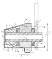
- FIG. 1 shows a cross section of a roller guide according to a first embodiment of the invention
- FIG. 2 shows a cross section of a roller guide according to a second embodiment of the invention
- FIG. 3 shows a cross section of a roller guide according to a third embodiment of the invention.
- FIG. 4 shows a cross section of a roller guide according to a fourth embodiment of the invention.
- FIG. 1 shows in cross section a roller guide according to a first embodiment of the invention.
- the guide rail 1 has a trapezium-shaped cross section, which includes a first side 1 a , a second side 1 b and an end side 1 c that represents the base line of the trapezium.
- the guide rail 1 is designed to be open in the region of a fourth side 1 d , which represents a second base line of the trapezium.
- the fourth side 1 d faces towards the center of the vehicle seat.
- the first side 1 a is oriented at an angle 2 with respect to an axle orientation.
- a support plane 3 serves to connect the rest of the vehicle seat (not shown) to the roller guide.
- a first roller 5 , a second roller 7 , and the support plane 3 are arranged on an axle 4 .
- the first and second rollers 5 , 7 are mounted on the axle 4 such that they can roll or slide.
- the first roller 5 has a bearing surface 5 a that is designed to be cone-shaped in such a way that it encloses an angle 6 with the axle orientation.
- the angle 6 corresponds to the angle 2 at which the bearing surface bears against the side 1 a.
- a bearing surface 7 a of the second roller 7 is oriented parallel to the axle orientation and, unlike the first roller 5 , does not bear against the side 1 a but rather against the side 1 b.
- the second roller 7 includes a first portion 8 and a second, shoulder-like portion 9 .
- At least one spring element 10 a is arranged between the rollers 5 , 7 in order to keep them at a permanent spacing
- an annular disc 10 b is arranged between the roller 7 and the support plane 3 in order to keep them at a permanent spacing.
- the first portion 8 of the second roller 7 has a diameter 11 which is smaller than a diameter 12 of the second, shoulder-like portion 9 .
- the shoulder-like portion 9 runs with its shoulder along a support surface 13 of the guide rail.
- the support surface 13 is oriented parallel to the base lines of the trapezium.
- FIG. 2 shows a cross section of a second embodiment of the invention.
- the roller guide shown therein once again includes the guide rail 1 , which has the trapezium-shaped design on the inside with the sides 1 a and 1 b and the end side 1 c which represents a base line of the trapezium.
- the design according to the second embodiment of the invention differs from the design of the first embodiment of the invention in that the bearing surface 7 a of the second roller 7 , like the side 1 b , is not oriented parallel to the running direction of the axle 4 but rather at an angle 14 .
- the angle 14 lies for example in the region of 5°
- the angle 2 of the first side and the bearing surface 5 a of the first roller lies in the region of 10°. Since the first angle 2 is greater than the second angle 14 , the first roller 5 can roll along the first side 1 a with one running direction without the bearing surface 7 a of the second roller 7 impairing or hindering this running direction which is opposed to its own running direction.
- FIG. 3 shows a cross section of a third embodiment of the invention.
- the roller 5 is rolled against the side 1 a .
- the roller 5 is at the same time arranged on the end of the axle 4 by means of a sliding or rolling bearing, so that radial forces of the axle 4 can be absorbed by the roller 5 .
- the second roller 7 once again has an angle 14 in its bearing surface 7 a , which angle makes it possible for the roller 7 to also absorb small axial force components in addition to the absorption of axial forces of the axle 4 by the roller 5 .
- the bearing surface 7 a of the second roller 7 rolls against the side 1 b
- the bearing surface 5 a of the first roller 5 rolls against the side 1 a .
- a spring element 10 b is located between the second roller 7 and the support plane 3 .
- FIG. 4 shows a cross section of a roller guide according to a fourth embodiment of the invention.
- oblique inner walls 15 a and 15 b of a guide rail 15 are not arranged on the upper and lower side of the guide rail, as in the case of the trapezium-shaped cross section with the sides 1 a and 1 b , but rather are arranged on the inner and outer side of the guide rail 15 .
- the guide rail 15 furthermore includes the inner end face 15 c and a further inner side 15 d.
- First and second rollers 17 and 21 have cone surfaces which are at angles 16 , 19 , 22 and 23 with respect to the longitudinal axis of an axle 18 .
- the first roller 17 is arranged to bear on the right-hand side against the oblique inner wall 15 a
- the second roller 21 rolls on the left-hand side against the inner wall 15 b of the guide rail 15 . In this way, the rollers 17 and 21 carry out opposite rolling movements about a further axle 20 .
- spring elements 24 a and 24 b are arranged in order to keep a sufficient spacing and thus to ensure that the vehicle seat (not shown here) which is fixed to the axle 18 is supplied with respect to the guide rail 15 when the seat is loaded.
Landscapes
- Engineering & Computer Science (AREA)
- Aviation & Aerospace Engineering (AREA)
- Transportation (AREA)
- Mechanical Engineering (AREA)
- Seats For Vehicles (AREA)
- Bearings For Parts Moving Linearly (AREA)
Applications Claiming Priority (3)
| Application Number | Priority Date | Filing Date | Title |
|---|---|---|---|
| DE102004038507.6 | 2004-08-07 | ||
| DE102004038507 | 2004-08-07 | ||
| DE102004038507A DE102004038507B4 (de) | 2004-08-07 | 2004-08-07 | Rollenführung für verstellbare Fahrzeugsitze |
Publications (2)
| Publication Number | Publication Date |
|---|---|
| US20060029308A1 US20060029308A1 (en) | 2006-02-09 |
| US7775718B2 true US7775718B2 (en) | 2010-08-17 |
Family
ID=35351676
Family Applications (1)
| Application Number | Title | Priority Date | Filing Date |
|---|---|---|---|
| US11/161,111 Expired - Fee Related US7775718B2 (en) | 2004-08-07 | 2005-07-22 | Roller guide for adjustable vehicle seats |
Country Status (4)
| Country | Link |
|---|---|
| US (1) | US7775718B2 (de) |
| EP (1) | EP1623867B1 (de) |
| CN (1) | CN1730314B (de) |
| DE (2) | DE102004038507B4 (de) |
Cited By (5)
| Publication number | Priority date | Publication date | Assignee | Title |
|---|---|---|---|---|
| US20080257328A1 (en) * | 2002-11-01 | 2008-10-23 | Black & Decker Inc. | Tile saw |
| US20100072800A1 (en) * | 2006-12-13 | 2010-03-25 | Thomas Weber | Vehicle seat, particularly commercial vehicle seat |
| US20120167703A1 (en) * | 2010-12-29 | 2012-07-05 | Hiwin Technology Corp. | Roller element for ball screw device |
| US20150231992A1 (en) * | 2012-08-14 | 2015-08-20 | Johnson Controls Components Gmbh & Co. Kg | Vehicle seat |
| US10906430B2 (en) * | 2019-02-11 | 2021-02-02 | Ford Global Technologies, Llc | Dual roller for a rail assembly |
Families Citing this family (11)
| Publication number | Priority date | Publication date | Assignee | Title |
|---|---|---|---|---|
| DE202007013640U1 (de) * | 2007-09-28 | 2009-02-12 | Paul Hettich Gmbh & Co. Kg | Möbelauszugsführung |
| CN102245429A (zh) * | 2008-12-15 | 2011-11-16 | 沃尔沃建筑设备公司 | 座椅悬挂设备和用于对引导组件施加预应力的方法 |
| DE102013208003B4 (de) * | 2013-04-09 | 2016-01-07 | Johnson Controls Components Gmbh & Co. Kg | Längseinsteller für einen Fahrzeugsitz und Fahrzeugsitz |
| DE102014005551B3 (de) * | 2014-04-16 | 2015-08-20 | Grammer Aktiengesellschaft | Fahrzeugsitz mit Rollenführung |
| JP6466095B2 (ja) * | 2014-07-29 | 2019-02-06 | シロキ工業株式会社 | 車両用スライドレール装置 |
| DE102016108159B4 (de) * | 2016-05-03 | 2020-06-18 | Grammer Aktiengesellschaft | Fahrzeugsitz mit Rollenführung |
| DE102017111206B4 (de) * | 2017-05-23 | 2020-06-18 | Grammer Aktiengesellschaft | Rollenführung |
| CN107031465A (zh) * | 2017-05-31 | 2017-08-11 | 长春富维安道拓汽车饰件系统有限公司 | 一种利用顶出块结构的悬浮间隙消除装置及间隙消除方法 |
| CN107054183A (zh) * | 2017-06-05 | 2017-08-18 | 长春富维安道拓汽车饰件系统有限公司 | 一种利用双滚轮结构的悬浮间隙消除装置及间隙消除方法 |
| DE102019206304B4 (de) * | 2018-05-04 | 2022-01-27 | Lear Corporation | Schienenanordnung |
| CN117485598B (zh) * | 2023-11-07 | 2026-03-27 | 山东航天电子技术研究所 | 一种可复位式压紧释放装置 |
Citations (5)
| Publication number | Priority date | Publication date | Assignee | Title |
|---|---|---|---|---|
| US1537084A (en) * | 1924-11-01 | 1925-05-12 | Ingersoll Rand Co | Roller guide for channeling steels |
| US3265450A (en) | 1963-10-17 | 1966-08-09 | Gen Motors Corp | Roller track apparatus |
| US4621784A (en) * | 1984-03-15 | 1986-11-11 | Brose Fahrzeugteile Gmbh & Co. Kg | Installation for the longitudinal adjustment of a seat |
| US4648141A (en) * | 1984-01-05 | 1987-03-10 | Mansouris Mansour N | Power operated separable beds and platform |
| US6264180B1 (en) | 1999-05-27 | 2001-07-24 | Sears Manufacturing Co. | Axially adjustable roller assembly |
Family Cites Families (3)
| Publication number | Priority date | Publication date | Assignee | Title |
|---|---|---|---|---|
| GB1441384A (en) * | 1972-08-12 | 1976-06-30 | Dunlop Ltd | Damping and guidance systems |
| US6200032B1 (en) * | 1999-07-09 | 2001-03-13 | Sears Manufacturing Co. | Seat suspension with dual roller assembly |
| EP1209024A1 (de) * | 2000-11-16 | 2002-05-29 | Johnson Controls Automotive Systems Corporation | Sitzgleitschiene |
-
2004
- 2004-08-07 DE DE102004038507A patent/DE102004038507B4/de not_active Expired - Fee Related
-
2005
- 2005-07-21 CN CN2005100856395A patent/CN1730314B/zh not_active Expired - Fee Related
- 2005-07-22 US US11/161,111 patent/US7775718B2/en not_active Expired - Fee Related
- 2005-08-05 EP EP05107225A patent/EP1623867B1/de not_active Expired - Lifetime
- 2005-08-05 DE DE502005010872T patent/DE502005010872D1/de not_active Expired - Lifetime
Patent Citations (5)
| Publication number | Priority date | Publication date | Assignee | Title |
|---|---|---|---|---|
| US1537084A (en) * | 1924-11-01 | 1925-05-12 | Ingersoll Rand Co | Roller guide for channeling steels |
| US3265450A (en) | 1963-10-17 | 1966-08-09 | Gen Motors Corp | Roller track apparatus |
| US4648141A (en) * | 1984-01-05 | 1987-03-10 | Mansouris Mansour N | Power operated separable beds and platform |
| US4621784A (en) * | 1984-03-15 | 1986-11-11 | Brose Fahrzeugteile Gmbh & Co. Kg | Installation for the longitudinal adjustment of a seat |
| US6264180B1 (en) | 1999-05-27 | 2001-07-24 | Sears Manufacturing Co. | Axially adjustable roller assembly |
Cited By (14)
| Publication number | Priority date | Publication date | Assignee | Title |
|---|---|---|---|---|
| US9044878B2 (en) | 2002-11-01 | 2015-06-02 | Black & Decker Inc. | Tile saw |
| US9623588B2 (en) | 2002-11-01 | 2017-04-18 | Black & Decker Inc. | Tile saw |
| US8001875B2 (en) * | 2002-11-01 | 2011-08-23 | Black & Decker Inc. | Tile saw |
| US20080257328A1 (en) * | 2002-11-01 | 2008-10-23 | Black & Decker Inc. | Tile saw |
| US9016180B2 (en) | 2002-11-01 | 2015-04-28 | Black & Decker Inc. | Tile saw |
| US11554516B2 (en) | 2002-11-01 | 2023-01-17 | Black & Decker, Inc. | Tile saw |
| US9073236B2 (en) | 2002-11-01 | 2015-07-07 | Black & Decker Inc. | Tile saw |
| US9738010B2 (en) | 2002-11-01 | 2017-08-22 | Black & Decker Inc. | Tile saw |
| US7988232B2 (en) * | 2006-12-13 | 2011-08-02 | Keiper Gmbh & Co. Kg | Vehicle seat, particularly commercial vehicle seat |
| US20100072800A1 (en) * | 2006-12-13 | 2010-03-25 | Thomas Weber | Vehicle seat, particularly commercial vehicle seat |
| US20120167703A1 (en) * | 2010-12-29 | 2012-07-05 | Hiwin Technology Corp. | Roller element for ball screw device |
| US9440559B2 (en) * | 2012-08-14 | 2016-09-13 | Johnson Controls Components Gmbh & Co. Kg | Vehicle seat |
| US20150231992A1 (en) * | 2012-08-14 | 2015-08-20 | Johnson Controls Components Gmbh & Co. Kg | Vehicle seat |
| US10906430B2 (en) * | 2019-02-11 | 2021-02-02 | Ford Global Technologies, Llc | Dual roller for a rail assembly |
Also Published As
| Publication number | Publication date |
|---|---|
| DE102004038507B4 (de) | 2008-04-10 |
| EP1623867B1 (de) | 2011-01-19 |
| CN1730314A (zh) | 2006-02-08 |
| EP1623867A2 (de) | 2006-02-08 |
| EP1623867A3 (de) | 2010-01-27 |
| CN1730314B (zh) | 2012-06-06 |
| DE502005010872D1 (de) | 2011-03-03 |
| DE102004038507A1 (de) | 2006-02-23 |
| US20060029308A1 (en) | 2006-02-09 |
Similar Documents
| Publication | Publication Date | Title |
|---|---|---|
| US7775718B2 (en) | Roller guide for adjustable vehicle seats | |
| US10583753B2 (en) | Roller guide | |
| US7988232B2 (en) | Vehicle seat, particularly commercial vehicle seat | |
| US12091079B2 (en) | Steering column for a motor vehicle | |
| US9573491B2 (en) | Longitudinal adjuster for a vehicle seat, and vehicle seat | |
| US7506732B2 (en) | Application device for a disk brake | |
| US9016950B2 (en) | Stabilized backing ring and stabilizing ring therefor | |
| JPH05141413A (ja) | 軸受組立体 | |
| US4486054A (en) | Recirculating rolling bearing | |
| EP0517642B1 (de) | Wälzlager mit modifizierter Kontaktgeometrie | |
| US8607939B2 (en) | Braking device, in particular for a motor vehicle | |
| US8435124B2 (en) | Variable length steering spindle | |
| US6200032B1 (en) | Seat suspension with dual roller assembly | |
| KR20190032367A (ko) | 스핀들 드라이브 | |
| US6648508B1 (en) | Linear guide | |
| US20030123925A1 (en) | Adjustable telescoping system for a bicycle | |
| US6557809B2 (en) | Universal seat track assembly | |
| CA1051388A (en) | Self-aligning wheel mounting structure | |
| CA2951981C (en) | Pull-out guide for furniture parts that can be moved in relation to each other | |
| US10596926B2 (en) | Seat tracking system | |
| CN107415780B (zh) | 具有滚子导向装置的车辆座椅 | |
| KR100485978B1 (ko) | 궤도차량보기의와전류브레이크현가장치 | |
| US6298791B1 (en) | Lateral suspension assembly for a guided vehicle system | |
| EP3339187A1 (de) | Fluggastbrücke | |
| AU2003203418A1 (en) | Telescope |
Legal Events
| Date | Code | Title | Description |
|---|---|---|---|
| AS | Assignment |
Owner name: GRAMMER AG, GERMANY Free format text: ASSIGNMENT OF ASSIGNORS INTEREST;ASSIGNORS:KOHL, JOSEP;HANER, MARKUS;REEL/FRAME:017070/0576 Effective date: 20050816 |
|
| FPAY | Fee payment |
Year of fee payment: 4 |
|
| FEPP | Fee payment procedure |
Free format text: MAINTENANCE FEE REMINDER MAILED (ORIGINAL EVENT CODE: REM.) |
|
| LAPS | Lapse for failure to pay maintenance fees |
Free format text: PATENT EXPIRED FOR FAILURE TO PAY MAINTENANCE FEES (ORIGINAL EVENT CODE: EXP.); ENTITY STATUS OF PATENT OWNER: LARGE ENTITY |
|
| STCH | Information on status: patent discontinuation |
Free format text: PATENT EXPIRED DUE TO NONPAYMENT OF MAINTENANCE FEES UNDER 37 CFR 1.362 |
|
| FP | Expired due to failure to pay maintenance fee |
Effective date: 20180817 |