US7749305B1 - Composite structure for high efficiency hydrogen separation containing preformed nano-particles in a bonded layer - Google Patents
Composite structure for high efficiency hydrogen separation containing preformed nano-particles in a bonded layer Download PDFInfo
- Publication number
- US7749305B1 US7749305B1 US11/515,976 US51597606A US7749305B1 US 7749305 B1 US7749305 B1 US 7749305B1 US 51597606 A US51597606 A US 51597606A US 7749305 B1 US7749305 B1 US 7749305B1
- Authority
- US
- United States
- Prior art keywords
- layer
- hydrogen
- porous
- hydrogen permeable
- permeable material
- Prior art date
- Legal status (The legal status is an assumption and is not a legal conclusion. Google has not performed a legal analysis and makes no representation as to the accuracy of the status listed.)
- Expired - Fee Related, expires
Links
- 239000001257 hydrogen Substances 0.000 title claims abstract description 221
- 229910052739 hydrogen Inorganic materials 0.000 title claims abstract description 221
- 239000002105 nanoparticle Substances 0.000 title claims abstract description 56
- 239000002131 composite material Substances 0.000 title abstract description 46
- 238000000926 separation method Methods 0.000 title description 5
- 125000004435 hydrogen atom Chemical class [H]* 0.000 title description 3
- UFHFLCQGNIYNRP-UHFFFAOYSA-N Hydrogen Chemical compound [H][H] UFHFLCQGNIYNRP-UHFFFAOYSA-N 0.000 claims abstract description 208
- 239000007787 solid Substances 0.000 claims abstract description 105
- 239000000463 material Substances 0.000 claims abstract description 90
- 238000000034 method Methods 0.000 claims abstract description 38
- 239000011148 porous material Substances 0.000 claims description 50
- 239000007789 gas Substances 0.000 claims description 26
- 238000004519 manufacturing process Methods 0.000 claims description 25
- 239000002245 particle Substances 0.000 claims description 14
- 238000000151 deposition Methods 0.000 claims description 13
- 239000012466 permeate Substances 0.000 claims description 11
- 230000008021 deposition Effects 0.000 claims description 7
- 239000000203 mixture Substances 0.000 claims description 4
- 150000002431 hydrogen Chemical class 0.000 abstract description 56
- 238000000746 purification Methods 0.000 abstract description 12
- KDLHZDBZIXYQEI-UHFFFAOYSA-N Palladium Chemical compound [Pd] KDLHZDBZIXYQEI-UHFFFAOYSA-N 0.000 description 79
- 229910001252 Pd alloy Inorganic materials 0.000 description 44
- 229910052763 palladium Inorganic materials 0.000 description 38
- 239000000758 substrate Substances 0.000 description 32
- 239000010408 film Substances 0.000 description 23
- 230000008569 process Effects 0.000 description 15
- 239000010949 copper Substances 0.000 description 13
- 229910052751 metal Inorganic materials 0.000 description 13
- 239000002184 metal Substances 0.000 description 13
- RYGMFSIKBFXOCR-UHFFFAOYSA-N Copper Chemical compound [Cu] RYGMFSIKBFXOCR-UHFFFAOYSA-N 0.000 description 12
- 229910052802 copper Inorganic materials 0.000 description 12
- 238000009792 diffusion process Methods 0.000 description 11
- 239000012528 membrane Substances 0.000 description 11
- 238000009713 electroplating Methods 0.000 description 9
- WFKWXMTUELFFGS-UHFFFAOYSA-N tungsten Chemical compound [W] WFKWXMTUELFFGS-UHFFFAOYSA-N 0.000 description 8
- 229910052721 tungsten Inorganic materials 0.000 description 8
- 239000010937 tungsten Substances 0.000 description 8
- 239000000356 contaminant Substances 0.000 description 7
- YZCKVEUIGOORGS-UHFFFAOYSA-N Hydrogen atom Chemical compound [H] YZCKVEUIGOORGS-UHFFFAOYSA-N 0.000 description 6
- 229910045601 alloy Inorganic materials 0.000 description 6
- 239000000956 alloy Substances 0.000 description 6
- 239000000843 powder Substances 0.000 description 6
- 238000004544 sputter deposition Methods 0.000 description 6
- 229910001220 stainless steel Inorganic materials 0.000 description 6
- 239000010935 stainless steel Substances 0.000 description 6
- 239000000919 ceramic Substances 0.000 description 5
- 230000003247 decreasing effect Effects 0.000 description 5
- OKTJSMMVPCPJKN-UHFFFAOYSA-N Carbon Chemical compound [C] OKTJSMMVPCPJKN-UHFFFAOYSA-N 0.000 description 4
- PXHVJJICTQNCMI-UHFFFAOYSA-N Nickel Chemical compound [Ni] PXHVJJICTQNCMI-UHFFFAOYSA-N 0.000 description 4
- 229910052799 carbon Inorganic materials 0.000 description 4
- 238000004663 powder metallurgy Methods 0.000 description 4
- VYZAMTAEIAYCRO-UHFFFAOYSA-N Chromium Chemical compound [Cr] VYZAMTAEIAYCRO-UHFFFAOYSA-N 0.000 description 3
- 238000000137 annealing Methods 0.000 description 3
- 230000004888 barrier function Effects 0.000 description 3
- 229910052804 chromium Inorganic materials 0.000 description 3
- 239000011651 chromium Substances 0.000 description 3
- 238000005137 deposition process Methods 0.000 description 3
- 238000013461 design Methods 0.000 description 3
- 238000010304 firing Methods 0.000 description 3
- 229910052709 silver Inorganic materials 0.000 description 3
- 239000004332 silver Substances 0.000 description 3
- 230000007704 transition Effects 0.000 description 3
- IJGRMHOSHXDMSA-UHFFFAOYSA-N Atomic nitrogen Chemical compound N#N IJGRMHOSHXDMSA-UHFFFAOYSA-N 0.000 description 2
- 241001189642 Theroa Species 0.000 description 2
- 239000011248 coating agent Substances 0.000 description 2
- 238000000576 coating method Methods 0.000 description 2
- 238000010276 construction Methods 0.000 description 2
- 238000011109 contamination Methods 0.000 description 2
- 230000000694 effects Effects 0.000 description 2
- 229930195733 hydrocarbon Natural products 0.000 description 2
- 150000002430 hydrocarbons Chemical class 0.000 description 2
- 150000002500 ions Chemical class 0.000 description 2
- 239000002086 nanomaterial Substances 0.000 description 2
- 229910052759 nickel Inorganic materials 0.000 description 2
- 239000010970 precious metal Substances 0.000 description 2
- 238000005245 sintering Methods 0.000 description 2
- 238000004528 spin coating Methods 0.000 description 2
- 238000005507 spraying Methods 0.000 description 2
- 229910001316 Ag alloy Inorganic materials 0.000 description 1
- 229910000881 Cu alloy Inorganic materials 0.000 description 1
- ZOKXTWBITQBERF-UHFFFAOYSA-N Molybdenum Chemical compound [Mo] ZOKXTWBITQBERF-UHFFFAOYSA-N 0.000 description 1
- 229910001257 Nb alloy Inorganic materials 0.000 description 1
- -1 PdFe Inorganic materials 0.000 description 1
- 229910002669 PdNi Inorganic materials 0.000 description 1
- 229910001362 Ta alloys Inorganic materials 0.000 description 1
- 229910000756 V alloy Inorganic materials 0.000 description 1
- 238000013459 approach Methods 0.000 description 1
- 230000015572 biosynthetic process Effects 0.000 description 1
- 230000007423 decrease Effects 0.000 description 1
- 238000007598 dipping method Methods 0.000 description 1
- 238000009826 distribution Methods 0.000 description 1
- 239000000428 dust Substances 0.000 description 1
- 238000007772 electroless plating Methods 0.000 description 1
- 238000005530 etching Methods 0.000 description 1
- 238000000605 extraction Methods 0.000 description 1
- 238000009472 formulation Methods 0.000 description 1
- 230000000670 limiting effect Effects 0.000 description 1
- 238000012423 maintenance Methods 0.000 description 1
- 230000000873 masking effect Effects 0.000 description 1
- 229910001092 metal group alloy Inorganic materials 0.000 description 1
- 238000012986 modification Methods 0.000 description 1
- 230000004048 modification Effects 0.000 description 1
- 229910052750 molybdenum Inorganic materials 0.000 description 1
- 239000011733 molybdenum Substances 0.000 description 1
- 229910052757 nitrogen Inorganic materials 0.000 description 1
- 238000007254 oxidation reaction Methods 0.000 description 1
- SWELZOZIOHGSPA-UHFFFAOYSA-N palladium silver Chemical compound [Pd].[Ag] SWELZOZIOHGSPA-UHFFFAOYSA-N 0.000 description 1
- 230000000737 periodic effect Effects 0.000 description 1
- 230000000704 physical effect Effects 0.000 description 1
- 238000002294 plasma sputter deposition Methods 0.000 description 1
- 239000012255 powdered metal Substances 0.000 description 1
- 238000007639 printing Methods 0.000 description 1
- 238000012545 processing Methods 0.000 description 1
- 230000009467 reduction Effects 0.000 description 1
- 230000002829 reductive effect Effects 0.000 description 1
- 230000002441 reversible effect Effects 0.000 description 1
- 238000007650 screen-printing Methods 0.000 description 1
- 229910001256 stainless steel alloy Inorganic materials 0.000 description 1
- 239000000725 suspension Substances 0.000 description 1
- 239000010409 thin film Substances 0.000 description 1
- 239000013008 thixotropic agent Substances 0.000 description 1
- 238000001771 vacuum deposition Methods 0.000 description 1
- 238000007740 vapor deposition Methods 0.000 description 1
- XLYOFNOQVPJJNP-UHFFFAOYSA-N water Chemical compound O XLYOFNOQVPJJNP-UHFFFAOYSA-N 0.000 description 1
- 238000009736 wetting Methods 0.000 description 1
Images


Classifications
-
- B—PERFORMING OPERATIONS; TRANSPORTING
- B01—PHYSICAL OR CHEMICAL PROCESSES OR APPARATUS IN GENERAL
- B01D—SEPARATION
- B01D53/00—Separation of gases or vapours; Recovering vapours of volatile solvents from gases; Chemical or biological purification of waste gases, e.g. engine exhaust gases, smoke, fumes, flue gases, aerosols
- B01D53/22—Separation of gases or vapours; Recovering vapours of volatile solvents from gases; Chemical or biological purification of waste gases, e.g. engine exhaust gases, smoke, fumes, flue gases, aerosols by diffusion
- B01D53/228—Separation of gases or vapours; Recovering vapours of volatile solvents from gases; Chemical or biological purification of waste gases, e.g. engine exhaust gases, smoke, fumes, flue gases, aerosols by diffusion characterised by specific membranes
-
- B—PERFORMING OPERATIONS; TRANSPORTING
- B01—PHYSICAL OR CHEMICAL PROCESSES OR APPARATUS IN GENERAL
- B01D—SEPARATION
- B01D69/00—Semi-permeable membranes for separation processes or apparatus characterised by their form, structure or properties; Manufacturing processes specially adapted therefor
- B01D69/12—Composite membranes; Ultra-thin membranes
- B01D69/1216—Three or more layers
-
- B—PERFORMING OPERATIONS; TRANSPORTING
- B01—PHYSICAL OR CHEMICAL PROCESSES OR APPARATUS IN GENERAL
- B01D—SEPARATION
- B01D71/00—Semi-permeable membranes for separation processes or apparatus characterised by the material; Manufacturing processes specially adapted therefor
- B01D71/02—Inorganic material
- B01D71/022—Metals
- B01D71/0223—Group 8, 9 or 10 metals
- B01D71/02232—Nickel
-
- C—CHEMISTRY; METALLURGY
- C01—INORGANIC CHEMISTRY
- C01B—NON-METALLIC ELEMENTS; COMPOUNDS THEREOF; METALLOIDS OR COMPOUNDS THEREOF NOT COVERED BY SUBCLASS C01C
- C01B3/00—Hydrogen; Gaseous mixtures containing hydrogen; Separation of hydrogen from mixtures containing it; Purification of hydrogen
- C01B3/50—Separation of hydrogen or hydrogen containing gases from gaseous mixtures, e.g. purification
- C01B3/501—Separation of hydrogen or hydrogen containing gases from gaseous mixtures, e.g. purification by diffusion
- C01B3/503—Separation of hydrogen or hydrogen containing gases from gaseous mixtures, e.g. purification by diffusion characterised by the membrane
- C01B3/505—Membranes containing palladium
-
- B—PERFORMING OPERATIONS; TRANSPORTING
- B01—PHYSICAL OR CHEMICAL PROCESSES OR APPARATUS IN GENERAL
- B01D—SEPARATION
- B01D2256/00—Main component in the product gas stream after treatment
- B01D2256/16—Hydrogen
-
- C—CHEMISTRY; METALLURGY
- C01—INORGANIC CHEMISTRY
- C01B—NON-METALLIC ELEMENTS; COMPOUNDS THEREOF; METALLOIDS OR COMPOUNDS THEREOF NOT COVERED BY SUBCLASS C01C
- C01B2203/00—Integrated processes for the production of hydrogen or synthesis gas
- C01B2203/04—Integrated processes for the production of hydrogen or synthesis gas containing a purification step for the hydrogen or the synthesis gas
- C01B2203/0405—Purification by membrane separation
Definitions
- the present invention relates to systems and methods that are used to separate molecular hydrogen from a volume of gas. More particularly, the present invention is related to systems and methods that separate hydrogen from a volume of mixed gas by exposing the mixed gas to a hydrogen permeable material through which only atomic hydrogen can readily pass.
- one of the most common ways to purify contaminated hydrogen gas is to pass the gas through a conduit made of a hydrogen permeable material, such as palladium or a palladium alloy.
- a conduit made of a hydrogen permeable material, such as palladium or a palladium alloy.
- atomic hydrogen permeates through the walls of the conduit, thereby separating from the contaminants.
- the conduit is kept internally pressurized and is typically heated to at least three hundred degrees centigrade.
- molecular hydrogen disassociates into atomic hydrogen on the surface of the conduit and the conduit absorbs the atomic hydrogen.
- the atomic hydrogen permeates through the conduit from a high pressure side of the conduit to a low pressure side of the conduit.
- the flow rate of hydrogen gas through the walls of a conduit is proportional to the length of the conduit and the thickness of the walls of the conduit.
- a highly efficient purification system would have a very long, very thin conduit to maximize flow rate.
- palladium is a very expensive precious metal. Consequently, conduits made of palladium and palladium alloys are very expensive to manufacture. As such, it is desirable to use as little of the palladium as possible in manufacturing a hydrogen gas purification system.
- conduits made from palladium and palladium alloys typically hold gas under pressure and at high temperatures. Accordingly, the walls of the conduit cannot be made too thin, else the conduit will either rupture or collapse depending on the pressure gradient present across the wall of the conduit.
- a typical prior art conduit made from palladium or a palladium alloy would have a wall thickness of approximately 80 ⁇ m.
- the thickness of the wall of the conduit is inversely proportional to the amount of purified hydrogen that passes through that wall in a given period of time. As such, in order to make the conduit more efficient, a thinner wall is desirable.
- a conduit wall cannot be made so thin that it ruptures or collapses under the pressure of the gases being passed through that conduit.
- conduits made from palladium and palladium alloys may become less efficient over time as the interior walls of the conduits become clogged with contaminants.
- many manufacturers attempt to clean the conduits by reverse pressurizing the conduits. In such a procedure, the exterior of the conduit is exposed to pressurized hydrogen. The hydrogen passes through the conduit wall and into the interior of the conduit. As the hydrogen passes into the interior of the conduit, the hydrogen may remove some of the contaminants that were deposited on the interior wall of the conduit.
- the conduits are capable of withstanding a fairly high pressure gradient when the interior of the conduit is pressurized higher than the exterior of the conduit.
- a much lower pressure gradient must be used, else the conduit will implode.
- Another prior art approach to limiting the amount of palladium used is to create membranes that are placed over apertures, like a skin on a drum. A pressure gradient is then created on opposite sides of the membrane, thereby causing hydrogen to flow through the membrane.
- Such prior art systems are exemplified by U.S. Pat. No. 5,734,092 to Wang et al., entitled Planar Palladium Structure.
- a problem associated with such prior art systems is that the palladium or palladium alloy membrane is typically positioned in a level plane, wherein a pressure gradient exists from one side of the membrane to the other. Since the membrane is flat, it has little structural integrity when trying to resist the forces created by the pressure gradient. Accordingly, in order to prevent the membrane from rupturing, solid perforated substrates are used to reinforce the membrane. The solid perforated substrates, however, are complicated to manufacture, restrict the flow through the membrane, and reduce the efficiency of the overall system.
- U.S. Pat. No. 6,152,987 to Ma entitled Hydrogen Gas-Extraction Module And Method Of Fabrication, discloses a hydrogen separator where a solid layer of hydrogen permeable material is deposited over a porous substrate of dissimilar material.
- the porous substrate supports the hydrogen permeable material and provides much more support than prior art mesh support systems.
- the porous substrate only allows gas to contact the hydrogen permeable material where a pore gap is exposed to the hydrogen permeable material. This configuration greatly limits the area of hydrogen permeable material actually exposed to gas.
- hydrogen permeable material deposited on a substrate of a dissimilar material tends to separate from the substrate. This can cause leakage of contaminated gas through the hydrogen permeable material and the eventual failure of the system.
- U.S. Patent Application No. 2003/0190486 to Roa et al also discloses a hydrogen separator where a solid layer of hydrogen permeable material is deposited over a porous substrate of dissimilar material.
- a palladium alloy is deposited over the porous substrate of dissimilar material using a first electroplating process. Copper is then deposited on the palladium in a second electroplating process. The palladium and copper layers are then annealed to produce a palladium alloy in place on the substrate.
- the porous substrate only allows gas to contact the hydrogen permeable material where a pore gap is exposed to the hydrogen permeable material. This configuration greatly limits the area of hydrogen permeable material actually exposed to gas.
- palladium alloy does not bond well to the porous substrate of dissimilar material. This leads to eventual failure.
- prior art systems such as the previously cited Ma patent and the Roa application, where palladium alloy is deposited directly on a porous substrate, another problem is that the substrates have large pore sizes to maximize exposure of the palladium alloy to gas. This requires that thick uneven layers of palladium be deposited over the porous substrate to cover the pores of the substrate. This causes faults in the layer of palladium that tend to fail over time.
- the porous layer of palladium alloy is still deposited directly onto the porous substrate of dissimilar material.
- the dissimilar materials bond poorly resulting in many eventual detachment flaws.
- the intermediate palladium alloy layer is deposited using electroplating techniques.
- electroplating ions of a metal are draw through an electroplating solution.
- Such an electroplating solution contains hydrocarbons.
- the ions of palladium alloy are deposited onto the porous stainless steel substrate, the deposited particles of palladium alloy tend to become coated in carbon from the electroplating solution.
- the carbon coating on the deposited particles of palladium alloy prevent hydrogen from being able to permeate through the palladium alloy. Rather, the carbon acts as a physical barrier between the palladium alloy and the hydrogen. This greatly inhibits the performance of the hydrogen separator.
- the present invention is a hydrogen purification system and method that utilizes a novel composite hydrogen separator.
- the composite hydrogen separator has a porous substrate.
- a first porous layer of a hydrogen permeable material is deposited in the porous substrate.
- the first porous layer includes premanufactured nano-particles of hydrogen permeable material that are deposited on a porous substrate in such a manner that the resultant layer of nano particles has the same physical structure as that of stack cannon balls. This results in a nano particle layer that is completely porous which means there are no-dead ends when molecules of gas are required to transition this layer.
- the nano particles can be made with a high temperature “ink jet printer type” of head and electrostatically deposited on the substrate with the appropriate amount of kinetic energy for set temperatures of the substrate and the source of nano particle so the resulting structure was the stacked cannon ball model.
- the porous layer of hydrogen permeable material supports the solid layer and enables the solid layer to withstand large pressure differentials. Furthermore, the porous layer of the hydrogen permeable material is diffusion bonded to the solid layer, thereby greatly increasing the effective surface area of the solid layer that is exposed to hydrogen gas. Accordingly, a large flow rate of hydrogen gas can be obtained in a small amount of space.
- FIG. 1 is a schematic of an exemplary embodiment of a hydrogen purification system
- FIG. 2 is a fragmented view of an exemplary embodiment of a composite hydrogen separator
- FIG. 3 is an enlarged view of section 3 previously shown in FIG. 2 ;
- FIG. 4 is a cross-sectional view of the base layer used in an exemplary embodiment of the present invention.
- FIG. 5 is a schematic of a manufacturing step used in production of an exemplary embodiment of the present invention.
- FIG. 6 is a schematic of a manufacturing step used in production of an exemplary embodiment of the present invention.
- FIG. 7 is a schematic of a manufacturing step used in production of an exemplary embodiment of the present invention.
- FIG. 8 is a schematic of a manufacturing step used in production of an exemplary embodiment of the present invention.
- FIG. 9 is a schematic of a manufacturing step used in production of an exemplary embodiment of the present invention.
- FIG. 10 is a schematic of an alternate manufacturing process used in production of an alternate exemplary embodiment of the present invention.
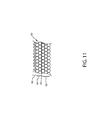
- FIG. 11 is a cross-sectional view of an alternate embodiment of a composite hydrogen separator.
- the present invention system provides a means for purifying a hydrogen gas at a high flow rate, using a small amount of space and a small amount of precious metals.
- the hydrogen purification system 10 contains a collection chamber 12 for collecting purified hydrogen gas. At least one supply conduit 14 extends into the collection chamber 12 where each of the supply conduits 14 is coupled to a source of contaminated hydrogen gas 16 .
- the supply conduit 14 is mostly fabricated from stainless steel or an equivalent alloy that is capable of retaining the contaminated hydrogen gas at a first pressure and at a predetermined operating temperature of at least three hundred degrees centigrade.
- the composite hydrogen separator 20 enables only pure hydrogen gas to permeate out of the supply conduit 14 and into the collection chamber 12 . Once, the purified hydrogen enters the collection chamber 12 it is collected for use.
- the composite hydrogen separator 20 is the only part of the purification system 10 that is permeable to hydrogen gas. As such, the flow capacity of the overall purification system 10 relies completely upon the flow capacity characteristics of the composite hydrogen separator 20 .
- the example of the composite hydrogen separator 20 that is illustrated is tubular in shape, wherein it defines an open central conduit 22 .
- the composite hydrogen separator 20 is attached to the supply conduit 14 .
- Contaminated hydrogen gas under pressure is passed through the central conduit 22 in the center of the composite hydrogen separator 20 .
- the pressure in the surrounding collection chamber 12 is kept lower than the pressure within the central conduit 22 .
- a pressure differential exists across the wall 24 of the composite hydrogen separator 20 that causes hydrogen gas to permeate through the structure of the composite hydrogen separator 20 .
- the greater the pressure differential between the conduit 22 in the composite hydrogen separator 20 and the collection chamber 12 the greater the rate of flow of hydrogen out of the composite hydrogen separator 20 .
- the direction of the flow can be controlled by selectively changing the direction of the pressure differential between the collection chamber 12 and the conduit 22 within the composite hydrogen separator 20 .
- the pressure within the composite hydrogen separator 20 is kept greater than the pressure within the collection chamber 12 .
- hydrogen gas flows out of the composite hydrogen separator 20 and is purified.
- the pressure of hydrogen gas within the collection chamber 12 can be made greater than the pressure of hydrogen within the composite hydrogen separator 20 .
- the hydrogen gas flows from the collection chamber 12 into the composite hydrogen separator 20 and can be used to remove contaminants that may have collected on the interior surfaces of the wall 24 of the composite hydrogen separator 20 .
- the wall 24 of the composite hydrogen separator 20 has a composite structure that is made using a unique combination of formation processes and techniques. Referring to FIG. 3 , an enlarged segment of FIG. 2 is shown. From FIG. 3 , it can be seen that the composition of the wall 24 of the composite hydrogen separator 20 changes across the thickness of the wall 24 . As such, the wall 24 is a composite structure of different materials.
- the first layer of the wall is the supporting base layer 30 .
- the base layer 30 is made of a non-reactive metal or metal alloy that in itself is not hydrogen permeable.
- the material selected for the base layer is stainless steel, tungsten or molybdenum.
- the base layer 30 of the wall 24 is porous and allows hydrogen gas to freely pass through the pores of its structure.
- the base layer 30 is made using traditional powder metallurgy techniques, where a powder of the non-reactive metal or alloy is formed into the desired shape and sintered into a porous form.
- the base layer 30 is manufactured so that it has pore size of approximately 0.7 ⁇ m prior to sintering. However, larger and smaller pore sizes can be used.
- At least one bonding layer 31 is deposited onto the base layer 30 .
- three bonding layers 31 are used.
- the bonding layers 31 are thin so that they do not close the pores in the base layer 30 .
- the first bonding layer 33 is preferably nickel or chromium. Such metal bond well to stainless steel alloys.
- the first bonding layer 33 is deposited directly onto the metal of the base layer 30 .
- the first bonding layer 33 bonds with the metal of the base layer 30 , as will later be explained.
- the second bonding layer 35 is a layer of tungsten or a metal from the same periodic family.
- the tungsten is deposited over the first bonding layer 33 and bonds to the material of the first bonding layer 33 .
- the third bonding layer 37 is a layer of copper or silver, depending upon the hydrogen permeable alloy to be used in the hydrogen separator 20 . If a palladium-silver alloy is used, silver is used as the third bonding layer 37 . However, it is preferred that a palladium-copper alloy be used. As such, copper is preferably used as the third bonding layer 37 .
- the silver or copper acts as a wetting layer in that it covers the second bonding layer 35 of tungsten and provides a surface onto which a palladium alloy can directly diffusion bond.
- a first porous layer 32 of hydrogen permeable material is formed upon the bonding layers 31 .
- the first porous hydrogen permeable layer 32 is preferably made from prefabricated nano particles of a hydrogen permeable material.
- the hydrogen permeable material can be a palladium alloy, such as Pd 1-x Ag x or Pd 1-x Cu x .
- other known hydrogen permeable alloys can also be used.
- Such alloys include, but are not limited to PdRu, PdAu, PdNi, PdFe, Niobium alloys, Tantalum alloys and Vanadium alloys.
- the nano particles of the hydrogen permeable material can be uniform in material. Alternatively, the nano particles can be ceramic balls that are coated with a hydrogen permeable material.
- the first porous layer 32 can be made from nano particles of a single size. However, in a preferred embodiment, the size of the palladium alloy nano particles in the first porous layer are graduated. As such, the palladium alloy nano particles become smaller the further those nano particles are from the bonding layers 31 and the base layer 30 .
- the first porous hydrogen permeable layer 32 can be formed in different ways, as will be later described.
- a solid layer 34 of palladium alloy or another hydrogen permeable material is deposited over the first porous hydrogen permeable layer 32 using one of the techniques later described.
- the hydrogen permeable material selected for the solid layer 34 is preferably the same material selected for the first porous hydrogen permeable layer 32 .
- the solid layer 34 and the first porous hydrogen permeable layer 32 share physical characteristics, such as thermal expansion.
- the solid layer 24 of hydrogen permeable material can be diffusion bonded to the first porous hydrogen permeable layer 32 .
- the deposited solid layer 34 of hydrogen permeable material is preferably between 0.05 microns and 0.20 microns thick.
- the deposited solid layer 34 diffusion bonds with the first porous hydrogen permeable layer 32 .
- the deposited solid layer 34 seals the pores of the first porous hydrogen permeable layer 32 .
- any hydrogen gas traveling through the wall 24 of the composite hydrogen separator 20 must permeate through the deposited solid layer 34 in order to advance.
- the deposited solid layer 34 of hydrogen permeable material is a second porous hydrogen permeable layer 36 .
- the second porous hydrogen permeable layer 36 is also made of the same hydrogen permeable material as the solid layer 34 .
- the second porous hydrogen permeable layer 36 is manufactured to be porous.
- the deposited solid layer 34 of hydrogen permeable material is interposed in between two porous layers 32 , 36 of hydrogen permeable material.
- the base layer 30 of non-reactive metal at the bottom of the wall 24 provides the wall 24 of the composite hydrogen separator 20 with physical strength. This base layer 30 prevents the composite hydrogen separator 20 from being easily inwardly crushed or outwardly expanded. Accordingly, the composite hydrogen separator 20 can withstand large pressure differentials without inwardly or outwardly deforming.
- the first porous hydrogen permeable layer 32 and the second porous hydrogen permeable layer 36 serve two purposes. First, these layers physically support the deposited solid layer 34 of hydrogen permeable material on either side of the solid layer 34 . Accordingly, the solid layer 34 of hydrogen permeable material is fully supported at nearly all points along its surface. However, although most all points of the solid layer 34 are supported, the entire solid layer 34 remains active in the permeation of hydrogen gas because the supporting porous layers 32 , 36 are also completely permeable to hydrogen gas. The solid layer 34 of hydrogen permeable material can therefore withstand very large pressure differentials between the sides of the solid layer 34 without rupturing.
- the first porous hydrogen permeable layer 32 and the second porous hydrogen permeable layer 36 do not obstruct the surface area of the solid layer 34 that is exposed to hydrogen gas. In fact, these porous layers 32 , 36 actually increase the effective surface area of the solid layer 34 .
- the first porous hydrogen permeable layer 32 and the second porous hydrogen permeable layer 36 are preferable made of the same material as the deposited solid layer 34 .
- the contact of the first porous hydrogen permeable layer 32 and the second porous hydrogen permeable layer 36 against the solid layer 34 therefore has the same effect as manufacturing the solid layer 34 with highly textured surfaces. This greatly increases the effective surface area that is exposed to hydrogen gas trying to permeate through the solid layer 34 .
- contaminated gas enters the conduit 22 in the center of the composite hydrogen separator 20 .
- the contaminated gas passes through the pores in the base layer 30 of the wall 24 .
- the contaminated gas also passes through the pores in the first porous hydrogen permeable layer 32 until it contacts the deposited solid layer 34 .
- the deposited solid layer 34 blocks all gases except hydrogen.
- the hydrogen permeates through the solid layer 34 where the hydrogen gas directly contacts the solid layer 34 .
- the hydrogen gas can also permeate into the areas of the first porous hydrogen permeable layer 32 that are contacting and supporting the deposited solid layer 34 . As a result, a very large surface area is available through which hydrogen gas can pass.
- the second porous hydrogen permeable layer 36 provides very little resistance to the further passage of the now purified hydrogen gas into the surrounding collection chamber 12 .
- the second porous hydrogen permeable layer 36 then acts to increase the effective surface area of the deposited solid layer 34 as hydrogen gas flows into the composite hydrogen separator 20 toward the central conduit 22 .
- the base layer 30 is preferably a sintered metal that is sintered into a porous form having a pore size of approximately 0.5 ⁇ m to 0.9 ⁇ m. An average pore size of 0.7 ⁇ m being preferred and used by way of example. Because of the overall process flexibility and geometric scaling, there is a considerable variation in possible average pore diameter.
- the base layer 30 can be sintered in the desired form 41 or a sintered block can be machined into the desired base form 41 . In the shown example, the desired base form 41 is a tubular section.
- individual bonding layers 33 , 35 , 37 are preferably deposited onto the base layer 30 using biased substrate sputtering, where the base layer 30 is the substrate.
- the base form 41 is placed in a vacuum deposition chamber, wherein each of the individual bonding layers 33 , 35 , 37 are deposited separately.
- the first bonding layer 33 of chromium or nickel is deposited in a layer of 0.03 microns. This initial sputtered layer promotes adhesion.
- the second bonding layer 35 of tungsten is deposited in a layer of 0.10 microns.
- the second bonding layer 35 of sputtered tungsten is for a diffusion barrier between the first bonding layer 33 and the subsequent third bonding layer 37 .
- the third bonding layer 37 of copper is deposited in a layer of 0.20 microns.
- the third bonding layer 37 of copper is for diffusion bonded to the porous layers that follow the sputtering process.
- the thickness of these three initial bonding layers 33 , 35 , 37 can be adjusted in accordance with the pore size of layer 30 . For the case of an average pore size of 0.7 ⁇ m, the thickness of the three bonding layers 33 , 35 , 37 is preferably what is stated in the example.
- the bonding layers 31 will have a combined thickness of 0.33 microns.
- the base layer 30 preferably has a pore size of 0.7 microns.
- the pore size present on the exterior of the assembly becomes smaller.
- the deposition of thin film material onto facing pore surfaces, obtained through substrate biasing, is controlled in a manner consistent with the specific to the vacuum system geometry, power distribution, and operating parameters during plasma sputtering.
- the 0.7 micron pores will be reduced in correspondence to the bonding layer thickness of 0.33 microns.
- the resulting new pore size will be 0.36 microns, or approximately a 50% reduction in diameter. However, the pores do remain open after the combined bonding layers 31 are applied.
- the flexibility in the process can be seen as a direct correspondence between the initial pore size of base layer 30 and the total thickness of the deposited bonding layers 33 , 35 , 37 .
- the larger the initial pore size in the base layer 30 the thicker the layer of deposited bonding layers 33 , 35 , 37 , since the pore size can be controlled by the thickness of the bonding layers 33 , 35 , 37 .
- the thickness of the bonding layers 33 , 35 , 37 may be approximately proportional to the original thickness stated for he base layer 30 .
- the materials described for the bonding layers 33 , 35 , 37 are exemplary and can be changed.
- the first two bonding layers 33 , 35 can be made from material that is not hydrogen permeable.
- the third bonding layer 37 can be made permeable to hydrogen by forming an alloy with subsequent layers for diffusion bonding.
- the first porous hydrogen permeable layer 32 is deposited over the bonding layers 33 , 35 , 37 .
- the first porous hydrogen permeable layer 32 is made of nano-particles of hydrogen permeable material.
- the nano-particles are prefabricated prior to use within the present invention. By manufacturing the nano-particles separately, the size and quality of the nano-particles can be controlled with great precision.
- the prefabricated nano-particles that form the first hydrogen permeable layer 32 can be deposited over the bonding layers 33 , 35 , 37 in a variety of ways.
- nano-particles of palladium and copper are suspended in a rheological vehicle, such as Hereaus-Cermalloy V633 or V636.
- rheological vehicles are thixotropic agents which are commonly used in nitrogen fireable thick film paste formulations.
- This suspension forms a thick paste film 43 .
- traditional thick film deposition techniques such as spin coating, ink head printing, spraying or screen printing, the thick film paste 43 is deposited over the bonding layers 31 . This creates a wet, four layered slug 45 .
- the prefabricated nano-particles particles of palladium and copper in the thick film paste 43 are larger than the pore openings in the underlying bonding layers 33 , 35 , 37 . Since the nano-particles are prefabricated, they are precise in size and do not fall into any pore opening.
- the thick film paste 43 is applied, it is fired.
- the firing can be performed at a temperature of 600° C. for several hours in an ambient containing several percent of hydrogen.
- the firing induces diffusion bonding between the palladium and the copper particles, producing a palladium alloy.
- the firing also induces diffusion bonding between the bonding layers 31 , the base layer 30 with the bonding layers 31 , and the bonding layers 31 with the first thick film layer 47 .
- This first thick film layer 47 is then bonded cohesively (sintered) and adhesively to the base layer 30 through bonding layers 31 .
- a five layered slug 49 is created having a porous base layer 30 , three bonding layers 31 and the first thick film layer 47 that are all diffusion bonded together.
- the first porous layer is comprised of premanufactured palladium alloy nano-particles that are then deposited on a porous substrate in such a manner that the resultant layer of deposited palladium nano particles has the same physical structure as that of stack cannon balls. This results in a palladium nano particle layer that is completely porous which means there are no-dead ends when molecules of gas are required to transition this layer.
- the palladium nano-particle deposition process will employ controlled application parameters and a controlled temperature of both the porous substrate and the palladium nano particles that are being deposited before they come in contact with the substrate or other palladium nano-particles on the substrate. This results in a palladium nano particle layer that is completely porous which means there are no-dead ends when molecules of gas are required to transition this layer.
- subsequent thick film layers can be deposited over the first thick film layer 47 , thereby growing the thickness of that layer.
- the five layered slug 49 is repeatedly subjected to thick film deposition and sintering. Each time a subsequent thick film layer is deposited, the size of the prefabricated nano-particles used in the thick film paste are decreased, thereby also decreasing the average pore between the particles.
- the subsequent layers of thick film are fired and the process is repeated until a first porous hydrogen permeable layer 32 is produced.
- the first porous hydrogen permeable layer 32 is comprised of a number of sintered nano-particle sub-layers, where the pore size of each subsequent sub-layer is decreased with respect to the prior layer, progressively decreasing until the final sub-layer has a pore size that reaches a designed value.
- the designed value of the pore size of the final sub-layer is in accordance with the thickness of the solid palladium layer that will be used.
- the microstructure of permeable layer 32 as a whole possesses the mechanical strength required to withstand the range of differential pressures across a solid palladium layer while in operation. That is, for small values of differential pressure, a solid palladium layer can be relatively thin, hence the final porous layer should possess a relatively small average pore size in order for the deposition of a solid palladium layer to close the pores.
- a thicker solid palladium layer may be required for mechanical strength, which therefore requires a thicker solid film and a larger pore size can be used.
- the design of the microstructure accounts for the practical range of operation of a solid palladium layer, while maximizing the permeance of the solid palladium layer by maintaining a minimum thickness of a solid palladium layer for the required mechanical strength.
- the design is therefore scalable in accordance with the pressure differential required for mechanical strength.
- the sub-layers produce a first porous hydrogen permeable layer 32 has a final thickness T 1 , which is the sum of the annealed thicknesses of all the thick film sub-layers that have been deposited.
- the first porous hydrogen permeable layer 32 is comprised of a single palladium alloy.
- the particle size and the pore size within the first porous hydrogen permeable layer 32 decreases as a function of distance from the base layer 30 . In the outer most application of thick film, it is preferred that the pore size after annealing be between 0.03 microns and 0.05 microns. This pore size produces a relatively smooth surface upon which a solid layer of material can later be deposited.
- a solid layer 34 of palladium alloy is deposited over the first porous hydrogen permeable layer 32 .
- Many deposition techniques can be used, such as vapor deposition, sputter deposition, spraying, spin coating, dipping, electroplating, or electroless plating.
- the minimum thickness of the solid layer 34 of palladium alloy is such that the pores are essentially closed after the deposition of the solid layer 34 .
- the thickness of the solid layer 34 can be about one-half the average pore size diameter of first porous hydrogen permeable layer 32 under the appropriate sputtering conditions.
- the thickness of the solid layer 34 of palladium be at least as thick as the pore size existing on the exterior of the first porous hydrogen layer 32 in order to compensate for the deviation in the actual pore.
- the solid layer 34 of palladium alloy seals the pores of the first porous hydrogen permeable layer 32 , thereby preventing any contaminant gas from flowing through the wall structure of the hydrogen separator.
- the surface on which the solid layer 34 is deposited is very even and smooth.
- the solid layer 34 of palladium covering this smooth layer can therefore be applied in an even layer with relatively small variations and imperfections.
- the size of the prefabricated nano-particles used within the second porous hydrogen permeable layer 36 can also be graduated by depositing multiple thick film layers onto the solid layer 34 of palladium alloy.
- the size of the pores in the second porous hydrogen permeable layer 36 that lay against the solid layer 34 of palladium alloy are preferably the same as the pore size in the first porous hydrogen permeable layer 32 immediately adjacent the solid layer 34 of palladium alloy.
- the contact of the first porous hydrogen permeable layer 32 and the second porous hydrogen permeable layer 36 with the solid layer 34 of palladium alloy increases the effective surface area of the solid layer 34 that is exposed to hydrogen gas diffusion.
- the purpose of this increase can be explained by considering the following example.
- the size of the prefabricated nano-particles in both the first porous hydrogen permeable layer 32 and the second porous hydrogen permeable layer 36 have an average diameter d on the surfaces that contact the solid layer 34 of palladium alloy.
- the surface area occupied by each powdered particle would be d 2 .
- the pore area created by the contact between nano-particles in each layer is d 2 (1 ⁇ n/4).
- each hemisphere of a nano-particle is d 2 (n/2).
- the sum of these areas is d 2 (1+n/4), which equals 1.79 d 2 .
- the solid layer 34 of hydrogen permeable material therefore has its surface areas effectively increased by approximately 79% by having the solid layer 34 supported by porous layers 32 , 36 of the same hydrogen permeable material.
- the porous layers 32 , 36 of hydrogen permeable material were described as being deposited as thick film layers using traditional thick film deposition techniques. Such techniques are preferred if the first and/or second porous layers of hydrogen permeable material are to have graduated particle and pore sizes. However, the first and/or second porous layers of hydrogen permeable material can be manufactured with one consistent particle size and pore size. In such a construction other manufacturing techniques are available.
- the material 40 such as tungsten or stainless steel, that is not hydrogen permeable is provided in powdered form having a known powder particle size.
- the powdered metal is processed in a first powder metallurgy process 42 , where the powder is compressed into a desired form and sintered.
- the result is a base layer slug 44 having a porous wall.
- Bonding layers are then applied to the base layer slug 44 using a repeated sputter deposition process 53 .
- the bonding layers are preferably chromium, tungsten and copper, as has previously been described. This creates a four layer slug 55 .
- the four layer slug 55 is then sent into a second powder metallurgy process 46 .
- pre manufactured and size-filtered particles of hydrogen permeable material are compressed around the four layer slug 55 and is sintered. This creates a five layer slug 48 .
- the five layer slug 48 is then taken into a deposition process 50 , where a solid layer of hydrogen permeable material is deposited around the five layer slug 48 , therein creating a six layer slug 52 .
- the deposition process 50 can be any known process by which a thin solid layer of hydrogen permeable material can be deposited onto the five layer slug 48 so as to coat the five layer slug 48 .
- the six layer slug 52 is then subjected to a third powder metallurgy process 54 where another layer of prefabricated nano-particles of hydrogen permeable material are compressed around the six layer slug 52 and sintered.
- the result is a complete seven layered composite hydrogen separator 59 .
- nano-particles are compacted and sintered to form the porous layers of hydrogen permeable material.
- the nano-particles need not be homogenous metal dust. Rather, it is possible to provide inert ceramic nano-particles and coat those ceramic nano-particles with palladium alloy or some other hydrogen permeable material.
- the coated ceramic nano-particles can then be compacted and sintered as though they were homogenous metal powder.
- the advantages of using coated ceramic nano-particles is that the particle size of the powder can be kept much more consistent than can solid metal powder. Thus, a more consistent pore size can be created in the porous layers.
- a single solid layer is used.
- the solid layer is surrounded by a layer of hydrogen permeable material that forms the exterior of the hydrogen separator.
- Such configurations are merely exemplary and it should be understood that layers within the hydrogen separator can be repeated or eliminated.
- a composite hydrogen separator with several layers is therefore possible with multiple deposited solid layers disposed between porous layers.
- FIG. 11 an alternate embodiment for the wall 60 of a composite hydrogen separator is shown.
- the composite wall 60 of the hydrogen separator only has six layers.
- the six layers are a base layer 62 , the three bonding layers 63 , a first hydrogen permeable layer 64 and a deposited solid layer 66 .
- the base layer 62 , the bonding layers 63 and the first porous hydrogen permeable layer 64 are the same as those previously described.
- the deposited solid layer 66 is now the outermost layer. To increase the surface area of the exterior of the deposited solid layer 66 , the exterior of the deposited solid layer 66 is contoured.
- the contouring can be created by masking sections of the solid layer 66 during deposition or etching the solid layer 66 after deposition.
- the contouring of the exterior of the deposited solid layer 66 serves to increase the exterior surface area of the solid layer 66 , thereby serving the same function as the second hydrogen permeable layer used in previous embodiments.
- the embodiment of FIG. 11 uses less palladium alloy than the previous embodiment's, and is thus less expensive.
- the hydrogen separator has been described in the form of a tubular conduit. It will be understood that such an embodiment is merely exemplary.
- the present invention hydrogen separator can be created in any shape, provided the hydrogen separator acts as a barrier between an area of contaminated hydrogen gas and an area of purified hydrogen gas.
Landscapes
- Chemical & Material Sciences (AREA)
- Organic Chemistry (AREA)
- Inorganic Chemistry (AREA)
- Chemical Kinetics & Catalysis (AREA)
- Engineering & Computer Science (AREA)
- Combustion & Propulsion (AREA)
- Analytical Chemistry (AREA)
- General Chemical & Material Sciences (AREA)
- Oil, Petroleum & Natural Gas (AREA)
- Separation Using Semi-Permeable Membranes (AREA)
- Hydrogen, Water And Hydrids (AREA)
Abstract
Description
Claims (12)
Priority Applications (1)
| Application Number | Priority Date | Filing Date | Title |
|---|---|---|---|
| US11/515,976 US7749305B1 (en) | 2003-06-04 | 2006-09-03 | Composite structure for high efficiency hydrogen separation containing preformed nano-particles in a bonded layer |
Applications Claiming Priority (3)
| Application Number | Priority Date | Filing Date | Title |
|---|---|---|---|
| US47562003P | 2003-06-04 | 2003-06-04 | |
| US10/770,732 US7125440B2 (en) | 2003-06-04 | 2004-02-02 | Composite structure for high efficiency hydrogen separation and its associated methods of manufacture and use |
| US11/515,976 US7749305B1 (en) | 2003-06-04 | 2006-09-03 | Composite structure for high efficiency hydrogen separation containing preformed nano-particles in a bonded layer |
Related Parent Applications (1)
| Application Number | Title | Priority Date | Filing Date |
|---|---|---|---|
| US10/770,732 Continuation-In-Part US7125440B2 (en) | 2003-06-04 | 2004-02-02 | Composite structure for high efficiency hydrogen separation and its associated methods of manufacture and use |
Publications (1)
| Publication Number | Publication Date |
|---|---|
| US7749305B1 true US7749305B1 (en) | 2010-07-06 |
Family
ID=42306998
Family Applications (1)
| Application Number | Title | Priority Date | Filing Date |
|---|---|---|---|
| US11/515,976 Expired - Fee Related US7749305B1 (en) | 2003-06-04 | 2006-09-03 | Composite structure for high efficiency hydrogen separation containing preformed nano-particles in a bonded layer |
Country Status (1)
| Country | Link |
|---|---|
| US (1) | US7749305B1 (en) |
Cited By (6)
| Publication number | Priority date | Publication date | Assignee | Title |
|---|---|---|---|---|
| US20080174040A1 (en) * | 2006-11-08 | 2008-07-24 | John Charles Saukaitis | Gas separation membrane system and method of making thereof using nanoscale metal material |
| US20090176012A1 (en) * | 2007-08-22 | 2009-07-09 | Way J Douglas | Unsupported Palladium Alloy Membranes and Methods of Making Same |
| US20100028703A1 (en) * | 2006-09-29 | 2010-02-04 | Rune Bredesen | Leak-proof membrane element and method of manufacturing such an element |
| US20100313754A1 (en) * | 2007-02-19 | 2010-12-16 | Mitsubishi Gas Chemical Company, Inc. | Hydrogen purification method, hydrogen separation membrane, and hydrogen purification apparatus |
| US20120012004A1 (en) * | 2010-07-16 | 2012-01-19 | Way J Douglas | Multilayer sulfur-resistant composite metal membranes and methods of making and repairing the same |
| US20140345462A1 (en) * | 2012-02-16 | 2014-11-27 | Fujifilm Corporation | Separation composite membrane and separating membrane module using the same |
Citations (12)
| Publication number | Priority date | Publication date | Assignee | Title |
|---|---|---|---|---|
| US4699637A (en) | 1983-09-08 | 1987-10-13 | Kernforschungsanlage Julich Gesellschaft Mit Beschrankter Haftung | Hydrogen permeation membrane |
| US5279731A (en) * | 1990-09-11 | 1994-01-18 | Pall Corporation | Depth filter media |
| US5498278A (en) * | 1990-08-10 | 1996-03-12 | Bend Research, Inc. | Composite hydrogen separation element and module |
| US5614001A (en) | 1994-05-23 | 1997-03-25 | Ngk Insulators, Ltd. | Hydrogen separator, hydrogen separating apparatus and method for manufacturing hydrogen separator |
| US5734092A (en) | 1995-05-31 | 1998-03-31 | Hewlett-Packard Company | Planar palladium structure |
| US6152987A (en) | 1997-12-15 | 2000-11-28 | Worcester Polytechnic Institute | Hydrogen gas-extraction module and method of fabrication |
| US20020141919A1 (en) * | 2001-03-30 | 2002-10-03 | Siemens Westinghouse Power Corporation | Metal gas separation membrane |
| US20020141920A1 (en) * | 2001-03-30 | 2002-10-03 | Alvin Mary Anne | Metal gas separation membrane module design |
| WO2003011433A1 (en) * | 2001-07-25 | 2003-02-13 | Fraunhofer-Gesellschaft zur Förderung der angewandten Forschung e.V. | Metal solution-diffusion membrane and method for producing the same |
| US6589312B1 (en) * | 1999-09-01 | 2003-07-08 | David G. Snow | Nanoparticles for hydrogen storage, transportation, and distribution |
| US20030190486A1 (en) | 2002-04-03 | 2003-10-09 | Fernando Roa | Process for Preparing Palladium Alloy Composite Membranes for Use in Hydrogen Separation, Palladium Alloy Composite Membranes and Products Incorporating or Made from the Membranes |
| US20040237779A1 (en) | 2003-03-21 | 2004-12-02 | Worcester Polytechnic Institute | Composite gas separation modules having intermediate porous metal layers |
-
2006
- 2006-09-03 US US11/515,976 patent/US7749305B1/en not_active Expired - Fee Related
Patent Citations (13)
| Publication number | Priority date | Publication date | Assignee | Title |
|---|---|---|---|---|
| US4699637A (en) | 1983-09-08 | 1987-10-13 | Kernforschungsanlage Julich Gesellschaft Mit Beschrankter Haftung | Hydrogen permeation membrane |
| US5498278A (en) * | 1990-08-10 | 1996-03-12 | Bend Research, Inc. | Composite hydrogen separation element and module |
| US5279731A (en) * | 1990-09-11 | 1994-01-18 | Pall Corporation | Depth filter media |
| US5614001A (en) | 1994-05-23 | 1997-03-25 | Ngk Insulators, Ltd. | Hydrogen separator, hydrogen separating apparatus and method for manufacturing hydrogen separator |
| US5734092A (en) | 1995-05-31 | 1998-03-31 | Hewlett-Packard Company | Planar palladium structure |
| US6152987A (en) | 1997-12-15 | 2000-11-28 | Worcester Polytechnic Institute | Hydrogen gas-extraction module and method of fabrication |
| US6589312B1 (en) * | 1999-09-01 | 2003-07-08 | David G. Snow | Nanoparticles for hydrogen storage, transportation, and distribution |
| US20020141920A1 (en) * | 2001-03-30 | 2002-10-03 | Alvin Mary Anne | Metal gas separation membrane module design |
| US20020141919A1 (en) * | 2001-03-30 | 2002-10-03 | Siemens Westinghouse Power Corporation | Metal gas separation membrane |
| WO2003011433A1 (en) * | 2001-07-25 | 2003-02-13 | Fraunhofer-Gesellschaft zur Förderung der angewandten Forschung e.V. | Metal solution-diffusion membrane and method for producing the same |
| US6964697B2 (en) * | 2001-07-25 | 2005-11-15 | Fraunhofer-Gesellschaft zur Förderung der angewandten Forschung e.V. | Metal solution-diffusion membrane and method for producing the same |
| US20030190486A1 (en) | 2002-04-03 | 2003-10-09 | Fernando Roa | Process for Preparing Palladium Alloy Composite Membranes for Use in Hydrogen Separation, Palladium Alloy Composite Membranes and Products Incorporating or Made from the Membranes |
| US20040237779A1 (en) | 2003-03-21 | 2004-12-02 | Worcester Polytechnic Institute | Composite gas separation modules having intermediate porous metal layers |
Cited By (11)
| Publication number | Priority date | Publication date | Assignee | Title |
|---|---|---|---|---|
| US20100028703A1 (en) * | 2006-09-29 | 2010-02-04 | Rune Bredesen | Leak-proof membrane element and method of manufacturing such an element |
| US8163064B2 (en) * | 2006-09-29 | 2012-04-24 | Sinvent As | Leak-proof membrane element and method of manufacturing such an element |
| US20080174040A1 (en) * | 2006-11-08 | 2008-07-24 | John Charles Saukaitis | Gas separation membrane system and method of making thereof using nanoscale metal material |
| US7959711B2 (en) * | 2006-11-08 | 2011-06-14 | Shell Oil Company | Gas separation membrane system and method of making thereof using nanoscale metal material |
| US20100313754A1 (en) * | 2007-02-19 | 2010-12-16 | Mitsubishi Gas Chemical Company, Inc. | Hydrogen purification method, hydrogen separation membrane, and hydrogen purification apparatus |
| US20090176012A1 (en) * | 2007-08-22 | 2009-07-09 | Way J Douglas | Unsupported Palladium Alloy Membranes and Methods of Making Same |
| US9044715B2 (en) | 2007-08-22 | 2015-06-02 | Colorado School Of Mines | Unsupported palladium alloy membranes and methods of making same |
| US20120012004A1 (en) * | 2010-07-16 | 2012-01-19 | Way J Douglas | Multilayer sulfur-resistant composite metal membranes and methods of making and repairing the same |
| US8778058B2 (en) * | 2010-07-16 | 2014-07-15 | Colorado School Of Mines | Multilayer sulfur-resistant composite metal membranes and methods of making and repairing the same |
| US20140345462A1 (en) * | 2012-02-16 | 2014-11-27 | Fujifilm Corporation | Separation composite membrane and separating membrane module using the same |
| US9314736B2 (en) * | 2012-02-16 | 2016-04-19 | Fujifilm Corporation | Separation composite membrane and separating membrane module using the same |
Similar Documents
| Publication | Publication Date | Title |
|---|---|---|
| US7125440B2 (en) | Composite structure for high efficiency hydrogen separation and its associated methods of manufacture and use | |
| JP4991381B2 (en) | Inorganic composite membrane for fluid separation | |
| US7749305B1 (en) | Composite structure for high efficiency hydrogen separation containing preformed nano-particles in a bonded layer | |
| JP4959804B2 (en) | Gas separation membrane system and method for making it using nanoscale metallic materials | |
| JP5997818B2 (en) | Sinter bonded porous metal coating | |
| JP4250525B2 (en) | Separation diffusion metal membrane and manufacturing method thereof | |
| US9555376B2 (en) | Multilayer, micro- and nanoporous membranes with controlled pore sizes for water separation and method of manufacturing thereof | |
| JP4729755B2 (en) | Composite membrane, method for producing the same, and hydrogen separation membrane | |
| US6913736B2 (en) | Metal gas separation membrane module design | |
| US8366805B2 (en) | Composite structures with porous anodic oxide layers and methods of fabrication | |
| JPH11276866A (en) | Hydrogen-permeable membrane and its manufacture | |
| US7771520B1 (en) | System and method for forming a membrane that is super-permeable to hydrogen | |
| WO2005075060A1 (en) | Composite structure for high efficiency hydrogen separation and its associated methods of manufacture and use | |
| CN110860213B (en) | Thin metal/ceramic hybrid membrane and filter | |
| JP2002219341A (en) | Supporting base for hydrogen-permselective membrane and hydrogen-permselective member | |
| US8002875B1 (en) | System and method for separating hydrogen gas from a mixed gas source using composite structure tubes | |
| KR101494186B1 (en) | Hydrogen separation membrane and manufacturing method thereof | |
| JP2002355537A (en) | Hydrogen permeable film and producing method thereof | |
| JP5568603B2 (en) | Method for producing porous body and inorganic selective membrane | |
| JP3174668B2 (en) | Hydrogen separation membrane | |
| RU2644640C2 (en) | Method of manufacturing composite membranes based on thin film of metals | |
| JP2005218963A (en) | Member for hydrogen permeation and its producing method | |
| KR101252569B1 (en) | Module configuration of hydrogen purification separation membrane module for the reduce of concentration polarization | |
| JP2005279484A (en) | Hydrogen permeable membrane and its manufacturing method | |
| KR20140132233A (en) | Hydrogen separation membrane module sing foil separation film and manufacturing method thereof |
Legal Events
| Date | Code | Title | Description |
|---|---|---|---|
| AS | Assignment |
Owner name: POWER & ENERGY, INC., PENNSYLVANIA Free format text: ASSIGNMENT OF ASSIGNORS INTEREST;ASSIGNOR:BOSSARD, PETER;REEL/FRAME:021185/0154 Effective date: 20080530 |
|
| FPAY | Fee payment |
Year of fee payment: 4 |
|
| FEPP | Fee payment procedure |
Free format text: MAINTENANCE FEE REMINDER MAILED (ORIGINAL EVENT CODE: REM.) |
|
| LAPS | Lapse for failure to pay maintenance fees |
Free format text: PATENT EXPIRED FOR FAILURE TO PAY MAINTENANCE FEES (ORIGINAL EVENT CODE: EXP.) |
|
| STCH | Information on status: patent discontinuation |
Free format text: PATENT EXPIRED DUE TO NONPAYMENT OF MAINTENANCE FEES UNDER 37 CFR 1.362 |
|
| FP | Lapsed due to failure to pay maintenance fee |
Effective date: 20180706 |
|
| AS | Assignment |
Owner name: GOLDMAN SACHS BANK USA, NEW YORK Free format text: SECURITY INTEREST;ASSIGNORS:ENTEGRIS, INC.;SAES PURE GAS, INC.;REEL/FRAME:048811/0679 Effective date: 20181106 |
|
| AS | Assignment |
Owner name: MORGAN STANLEY SENIOR FUNDING, INC., MARYLAND Free format text: ASSIGNMENT OF PATENT SECURITY INTEREST RECORDED AT REEL/FRAME 048811/0679;ASSIGNOR:GOLDMAN SACHS BANK USA;REEL/FRAME:050965/0035 Effective date: 20191031 |
|
| AS | Assignment |
Owner name: TRUIST BANK, AS NOTES COLLATERAL AGENT, NORTH CAROLINA Free format text: SECURITY INTEREST;ASSIGNORS:ENTEGRIS, INC.;ENTEGRIS GP, INC.;POCO GRAPHITE, INC.;AND OTHERS;REEL/FRAME:060613/0072 Effective date: 20220706 |