US7733654B2 - Heat dissipation module - Google Patents
Heat dissipation module Download PDFInfo
- Publication number
- US7733654B2 US7733654B2 US12/230,479 US23047908A US7733654B2 US 7733654 B2 US7733654 B2 US 7733654B2 US 23047908 A US23047908 A US 23047908A US 7733654 B2 US7733654 B2 US 7733654B2
- Authority
- US
- United States
- Prior art keywords
- heat
- heat dissipation
- diversion pipeline
- diversion
- wall
- Prior art date
- Legal status (The legal status is an assumption and is not a legal conclusion. Google has not performed a legal analysis and makes no representation as to the accuracy of the status listed.)
- Expired - Fee Related, expires
Links
Images


Classifications
-
- H10W40/47—
-
- H10W40/43—
Definitions
- the invention relates to a heat dissipation module, and more particularly relates to a heat dissipation module applied to cooling a microprocessor.
- the heat dissipation module 100 is connected to a water pump 200 and a heat source, such as CPU 300 .
- the heat dissipation module 100 includes a copper pipe 120 , a plurality of radiator fins 140 , a cooling plate 160 and a fan 180 .
- the radiator fin 140 is assembled outside of the copper pipe 120 .
- the fan 180 is disposed by side of the copper pipe 120 and the radiator fin 140 , to provide cool air.
- the cooling plate 160 is fixed on the CPU 300 .
- the water pump 200 pumps the water in the copper pipe 120 of the heat dissipation module 100 to the cooling plate 160 to absorb the heat generated from the CPU 300 .
- the water returns to the heat dissipation module 100 to exchange heat after absorbing energy, referring to the heat exchange path in FIG. 1D , which is described in details in following. After cooled, the water is pumped to the cooling plate 160 to keep the CPU 300 in low temperature.
- FIG. 1B for the A-A section view of the copper pipe 120 and the radiator fin 140 in FIG. 1A .
- the water 130 flows in the copper pipe 120 , while the outer wall of the copper pipe 120 contacts with the annular radiator fin 140 .
- the heat absorbed by the water 130 may transfer to the surface of the radiator fin 140 through the copper pipe 120 and exchange with the cool air from the fan 180 to reduce the heat in the water 130 .
- the radiator fin 140 curves in L-type, with a connection portion 142 and a fin 144 .
- the connection portion 142 is parallel to the outer wall of the copper pipe 120 and installed on the outer wall of the copper pipe 120 by welding or tight fitting.
- the fin 144 is vertical to the copper pipe 120 to contact cool air.
- the disadvantages for this structure is as follows: 1. there is a tiny space 150 between the fin 144 and the copper pipe 120 , which causes the contact thermal resistance and bad heat conduction; 2. the copper pipe 120 reacts with the water 130 , generating the copper rust; 3. the copper pipe 120 has a high price and a large weight, unfavorable for large yield.
- one part 120 a of the copper pipe 120 in FIG. 1A is enlarged for detailed description.
- the arrow in a pipe-wall 122 of the copper pipe 120 stands for the flow direction of the water 130 and the ⁇ points the flow direction of the cool air toward the outside of the surface of the paper.
- the water 130 flows from one upstream portion 124 of the copper pipe 120 into the pipe-wall 122 and down to one downstream portion 126 of the copper pipe 120 .
- the heat in the water 130 is transferred to the radiator fin 140 through the pipe-wall 122 .
- the fan 180 generates an air flow passing the outer side of the pipe-wall 122 , thus the cool air exchanges with the hot radiator fin 140 to cool the water.
- the heat conduction efficiency of the radiator fin 140 is proportional to the temperature difference of the water in the upstream portion and the downstream portion.
- the pipe-wall 122 of the copper pipe 120 has a certain thickness and the copper is a good conductor for heat, so when the temperature in the upstream portion 124 of the copper pipe 120 is just to rise, the heat is transferred to the low-temperature downstream portion 126 through the pipe-wall 122 along the flow direction of the water 130 before it is transferred to the first radiator fin 140 outside the pipe-wall 122 , as the broken lines shows.
- the temperature in the upstream portion 124 is lowered, while the temperature in the downstream portion 126 is raised, so the temperature difference of the water in the upstream portion 124 and downstream portion 126 is reduced and the heat conduction efficiency gets worse.
- the object of the present invention is to provide a heat dissipation module for improving the heat conduction efficiency of the radiator fin.
- one embodiment of the present invention provides a heat dissipation module applied to cooling a microprocessor.
- the heat dissipation module includes a base, a diversion pipeline, a plurality of heat conductive pieces and a fan.
- the base is assembled on the microprocessor.
- the diversion pipeline is connected to the base, provides a diversion direction and has a heat insulated pipe-wall.
- the diversion pipeline is partitioned off into an inside portion and an outside portion with the heat insulated pipe-wall.
- the heat insulated pipe-wall reduces the heat conduction in the diversion direction of the diversion pipeline.
- the plurality of heat conductive pieces are fixed on the diversion pipeline.
- Each two neighboring heat conductive pieces are separated with the heat insulated pipe-wall of the diversion pipeline.
- Each of the heat conductive pieces has a heat dissipation direction from the inside portion to the outside portion of the diversion pipeline and across the diversion direction.
- the fan is assembled on the outside portion of the diversion pipeline, and provides a cool air for the heat conductive pieces.
- a heat dissipation module including a diversion pipeline, a plurality of heat conductive pieces.
- the diversion pipeline provides a diversion direction and has a heat insulated pipe-wall.
- the heat insulated pipe-wall reduces the heat conduction in the diversion direction of the diversion pipeline.
- the plurality of heat conductive pieces are fixed on the heat insulated pipe-wall. Each two neighboring heat conductive pieces are separated with the heat insulated pipe-wall of the diversion pipeline, and each of the heat conductive pieces has a heat dissipation direction substantially vertical to the diversion direction.
- FIGS. 1A-1D are the schematic views of the structure of a conventional heat dissipation module
- FIG. 2A is the schematic view showing an embodiment of a heat dissipation module according to the present invention.
- FIG. 2B is the schematic view showing the heat insulated pipe-wall and a heat conductive piece of a diversion pipeline of the heat dissipation module according to one embodiment of the present invention
- FIG. 2C is the A-A section view of the heat dissipation module in FIG. 2A ;
- FIG. 2D is the B-B section view of the heat dissipation module in FIG. 2C ;
- FIG. 3 is the schematic view showing an embodiment of the heat dissipation module according to the present invention.
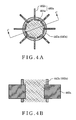
- FIGS. 4A-4B is the schematic view showing the heat conductive piece of the heat dissipation module according to one embodiment of the present invention.
- FIGS. 5A-5B is the schematic view showing the heat conductive piece of the heat dissipation module according to one embodiment of the present invention.
- FIGS. 6A-6C is the schematic view showing the heat conductive piece of the heat dissipation module according to one embodiment of the present invention.
- FIG. 7 is the schematic view showing a simulation device of the heat dissipation module according to one embodiment of the present invention.
- the description of “A” component facing “B” component herein may contain the situations that “A” component directly faces “B” component or one or more additional components are between “A” component and “B” component.
- the description of “A” component “adjacent to” “B” component herein may contain the situations that “A” component is directly “adjacent to” “B” component or one or more additional components are between “A” component and “B” component. Accordingly, the drawings and descriptions will be regarded as illustrative in nature and not as restrictive.
- a heat dissipation module 400 is used to cool a microprocessor 500 , such as the CPU.
- the heat dissipation module 400 includes a base 420 , a diversion pipeline 440 , a plurality of heat conductive pieces 460 and a fan 480 .
- the base 420 is assembled on the microprocessor 500 .
- the diversion pipeline 440 has an opening(not shown) and a heat insulated pipe-wall 442 . The opening is connected to the base 420 .
- the diversion pipeline 440 provides a diversion direction.
- the diversion pipeline 440 is partitioned off into and inside portion and an outside portion with the heat insulated pipe-wall 442 , and the heat insulated pipe-line 442 extends along the diversion direction (shown as arrow) and also reduces the heat conduction in the diversion direction of the diversion pipeline 440 .
- the heat conductive pieces 460 are fixed on the heat insulated pipe-wall 442 . Each two neighboring heat conductive pieces 460 are separated with the heat insulated pipe-wall 442 .
- the heat conductive piece 460 has a heat dissipation direction from the inside portion to the outside portion of the diversion pipeline 440 , and across or substantially vertical to the diversion direction.
- the fan 480 is assembled on the outside of the diversion pipeline 440 and the heat conductive pieces 460 , and provides a cool air for the heat conductive pieces 460 .
- the heat dissipation module 400 further includes a pump 600 .
- the inlet and outlet of the pump 600 are connected separately with the two end apertures 424 and 426 , to facilitate the flowing of the fluid in the flow path 422 and the diversion pipeline 440 , in which the pump 600 , the base 420 and the diversion pipeline 440 form an enclosed circle.
- the heat insulated pipe-wall 442 of the diversion pipeline 440 is made of the material with the thermal conductivity lower than 20 W/m ⁇ K, such as plastic, silicon rubber.
- the air or water flows in the diversion pipeline 440 along the diversion direction.
- the heat conductive piece 460 is penetrating the heat insulated pipe-wall 442 , arranged along the diversion direction(shown as arrow). There is a space D between each two neighboring heat conductive pieces 460 .
- the heat conduction in the diversion direction of the diversion pipeline 440 is blocked by the heat insulated pipe-wall 442 within the space D, so there is no or very slow heat conduction between the two neighboring heat conductive pieces 460 .
- the heat conductive pieces 460 are made of the material with the thermal conductivity higher than 50 W/m ⁇ K, such as copper, aluminum, in the way of die-casting, cold forging and extruding, penetrating the heat insulated pipe-wall 442 in radial distribution.
- Each of the heat conductive pieces 460 in FIG. 2C has an outer fin 462 and an inner fin 464 .
- the inner fin 464 is disposed inside the heat insulated pipe-wall 442 of the diversion pipeline 440
- the outer fin 462 is disposed outside the heat insulated pipe-wall 442 of the diversion pipeline 440 .
- each of the heat conductive pieces 460 is disposed outside the diversion pipeline 440 , while the other end is disposed inside the diversion pipeline 440 .
- the inner fin 464 absorbs the heat from the diversion pipeline 440 and transfers the heat to the outer fin 462 .
- the inner fin 464 in FIG. 2C is substantially vertical to the inner surface of the heat insulated pipe-wall 442
- the outer fin 462 is also substantially vertical to the outer surface of the heat insulated pipe-wall 442 .
- the inner fin 464 and the outer fin 462 in this embodiment are both vertical to the heat insulated pipe-wall 442 approximately.
- Each of the heat conductive pieces 460 has a heat dissipation surface 468 parallel to the diversion direction of the diversion pipeline 440 .
- a heat dissipation module 700 has an upright diversion pipeline 720 , such as heat pipe, and a plurality of heat conductive pieces 740 .
- a heat insulated pipe-wall 722 of the diversion pipeline 720 includes a plurality of plastic tube sections(no mark) fitted over each other (referring to FIG. 6C ).
- Each of the plastic tube sections is connected with a heat conductive piece 740 .
- the interfaces between each two adjacent plastic tube sections, or between the plastic tube section and the heat conductive piece 740 are glued.
- a heat dissipation base 760 transfers the heat generated by the microprocessor 500 to the liquid water at the bottom of the diversion pipeline 720 , the liquid water will be vaporized and formed hydrosphere.
- the hydrosphere rises and contacts an inner fin 742 .
- the inner fin 742 transfers the heat in the hydrosphere to an outer fin 744 .
- the hydrosphere is condensed to liquid water at the inner fin 742 and returns to the heat dissipation base 760 due to the gravity.
- FIGS. 4A-4B , FIGS. 5A-5B , FIGS. 6A-6C for different types of heat conductive pieces.
- a heat dissipation surface 468 of the heat conductive piece 460 is extended in the diversion direction.
- An inner fin 464 a of a heat conductive piece 460 a in FIG. 4A is formed by bending the inner fin 464 as shown in FIG.
- FIG. 4B is the C-C section view of FIG. 4A , showing the vertical setting of the outer fin 462 a and the heat insulated pipe-wall 442 a of the diversion pipeline 440 a.
- FIGS. 5A and 5B an inner fin 464 b and an outer fin 462 b of the heat conductive piece 460 b are connected in L-type.
- the outer fin 462 b has a heat dissipation surface 468 b vertical to the diversion direction(in FIG. 5A , the diversion direction is vertical to the surface of the paper).
- the heat conductive piece 460 b is placed by rotating the heat conductive piece 460 a in FIG. 4A 90 degree clockwise or anticlockwise relative to the heat insulated pipe-wall 442 a of the diversion pipeline 440 a , so that the flow resistance in the diversion pipeline 440 a and the number of the heat conductive pieces 460 b may be reduced.
- FIG. 5B is the D-D section view of FIG. 5A , showing that the outer fin 462 b is vertical to a heat insulated pipe-wall 442 b and the bending direction of the inner fin 464 b is parallel to the diversion direction.
- the heat insulated pipe-wall of a diversion pipeline 440 c includes a plurality of rings 442 c fitted over each other, and the rings 442 c is made of the heat insulated material or low thermal conductivity material.
- a plurality of heat conductive pieces 460 c are disposed on different rings 442 c separately.
- Each of the heat conductive pieces 460 c includes a disk outer fin 462 c and a plurality of inner fins 464 c .
- the disk outer fin 462 c surrounds the corresponding ring 442 c , while the inner fins 464 c is disposed inside the corresponding ring 442 c .
- Each of the inner fins 464 c has a heating surface 466 c and each of the disk outer fins 462 c has a heat dissipation surface 468 c , the heating surface 466 c vertical to the heat dissipation surface 468 c.
- a plurality of the rings 442 c and the heat conductive pieces 460 c are alternatively connected with each other.
- Glue is coated on the interface of the ring 442 c and its adjacent heat conductive piece 460 c to avoid leakage; or pressing the integral to deform the ring 442 c to avoid leakage.
- FIG. 7 for the heat flow simulation in one part of the diversion pipeline.
- one part of the diversion pipeline 722 a is picked as FIG. 3 shows, which includes a heat insulated pipe-wall 722 and the heat conductive piece 740 .
- the top of the heat insulated pipe-wall 722 is called hot end, the bottom called cool end.
- a hot flow is provided flowing from the air inlet Hin of the hot end to the air outlet Hout of the hot end
- a cool flow is provided flowing from the air inlet Cin of the cool end to the air outlet Cout of the cool end.
- the temperature of the air inlet Hin of the hot end is 70° C.
- the air inlet Cin of the cool end is 25° C.
- the flux of the cool flow and the hot flow are the same (for example, 1 cfm)
- the temperature of the air outlet Cout of the cool end is 61° C.
- the temperature of the air outlet Cout of the cool end is 54° C.
- the heat insulated pipe-wall made of plastic increases 24%[(54 ⁇ 25)/(61 ⁇ 25)] compared to the heat insulated pipe-wall made of aluminum. Therefore, the heat exchange will be favored by blocking the heat diversion in the diversion pipeline 772 a.
- the heat dissipation module in the present invention achieves low cost, light weight and small volume with high heat dissipation efficiency.
- the term “the invention”, “the present invention” or the like does not necessarily limit the claim scope to a specific embodiment, and the reference to particularly preferred exemplary embodiments of the invention does not imply a limitation on the invention, and no such limitation is to be inferred.
- the invention is limited only by the spirit and scope of the appended claims.
- the abstract of the disclosure is provided to comply with the rules requiring an abstract, which will allow a searcher to quickly ascertain the subject matter of the technical disclosure of any patent issued from this disclosure. It is submitted with the understanding that it will not be used to interpret or limit the scope or meaning of the claims. Any advantages and benefits described may not apply to all embodiments of the invention.
Landscapes
- Cooling Or The Like Of Electrical Apparatus (AREA)
- Cooling Or The Like Of Semiconductors Or Solid State Devices (AREA)
Abstract
Description
Claims (23)
Applications Claiming Priority (3)
| Application Number | Priority Date | Filing Date | Title |
|---|---|---|---|
| TW096146661 | 2007-12-07 | ||
| TW96146661A | 2007-12-07 | ||
| TW096146661A TWI336832B (en) | 2007-12-07 | 2007-12-07 | Heat dissipation module |
Publications (2)
| Publication Number | Publication Date |
|---|---|
| US20090147454A1 US20090147454A1 (en) | 2009-06-11 |
| US7733654B2 true US7733654B2 (en) | 2010-06-08 |
Family
ID=40721422
Family Applications (1)
| Application Number | Title | Priority Date | Filing Date |
|---|---|---|---|
| US12/230,479 Expired - Fee Related US7733654B2 (en) | 2007-12-07 | 2008-08-29 | Heat dissipation module |
Country Status (2)
| Country | Link |
|---|---|
| US (1) | US7733654B2 (en) |
| TW (1) | TWI336832B (en) |
Cited By (5)
| Publication number | Priority date | Publication date | Assignee | Title |
|---|---|---|---|---|
| US20100044346A1 (en) * | 2008-08-20 | 2010-02-25 | Abb Technology Ag | High-voltage switch with cooling |
| US20110122579A1 (en) * | 2008-07-25 | 2011-05-26 | Koninklijke Phiips Electronics N.V. | Cooling device for cooling a semiconductor die |
| US20110299227A1 (en) * | 2010-06-04 | 2011-12-08 | Mitsubishi Electric Corporation | Gas insulated switchgear |
| US8550650B1 (en) | 2010-08-10 | 2013-10-08 | Patrick McGinty | Lighted helmet with heat pipe assembly |
| WO2021035760A1 (en) * | 2019-08-31 | 2021-03-04 | 华为技术有限公司 | Heat dissipation apparatus, device, equipment rack, and system |
Families Citing this family (6)
| Publication number | Priority date | Publication date | Assignee | Title |
|---|---|---|---|---|
| EP1983623A1 (en) * | 2007-04-18 | 2008-10-22 | Eaton Electric B.V. | Cooling arrangement for conductor in electrical installation |
| TWI607533B (en) * | 2016-08-31 | 2017-12-01 | 奇鋐科技股份有限公司 | Water-cooling radiator structure |
| CN110430738B (en) * | 2019-08-28 | 2024-04-12 | 国能神福(晋江)热电有限公司 | Cooling device |
| CN110850939B (en) * | 2019-10-17 | 2021-02-19 | 王昌东 | Heat dissipation device for reinforcing server |
| CN112490206B (en) * | 2020-12-07 | 2023-01-10 | 珠海格力电器股份有限公司 | Heat dissipation structure of switch tube, converter and air conditioner |
| CN116367480B (en) * | 2023-06-02 | 2023-08-08 | 成都贡爵微电子有限公司 | High-isolation airtight microwave assembly |
Citations (1)
| Publication number | Priority date | Publication date | Assignee | Title |
|---|---|---|---|---|
| US20030056943A1 (en) | 2000-04-12 | 2003-03-27 | Dessiatoun Serguei Vassilievich | Heat transfer |
-
2007
- 2007-12-07 TW TW096146661A patent/TWI336832B/en not_active IP Right Cessation
-
2008
- 2008-08-29 US US12/230,479 patent/US7733654B2/en not_active Expired - Fee Related
Patent Citations (1)
| Publication number | Priority date | Publication date | Assignee | Title |
|---|---|---|---|---|
| US20030056943A1 (en) | 2000-04-12 | 2003-03-27 | Dessiatoun Serguei Vassilievich | Heat transfer |
Cited By (9)
| Publication number | Priority date | Publication date | Assignee | Title |
|---|---|---|---|---|
| US20110122579A1 (en) * | 2008-07-25 | 2011-05-26 | Koninklijke Phiips Electronics N.V. | Cooling device for cooling a semiconductor die |
| US8559175B2 (en) * | 2008-07-25 | 2013-10-15 | Koninlijke Philips N.V. | Cooling device for cooling a semiconductor die |
| US20100044346A1 (en) * | 2008-08-20 | 2010-02-25 | Abb Technology Ag | High-voltage switch with cooling |
| US8081464B2 (en) * | 2008-08-20 | 2011-12-20 | Abb Technology Ag | High-voltage switch with cooling |
| US20110299227A1 (en) * | 2010-06-04 | 2011-12-08 | Mitsubishi Electric Corporation | Gas insulated switchgear |
| US8675350B2 (en) * | 2010-06-04 | 2014-03-18 | Mitsubishi Electric Corporation | Gas insulated switchgear |
| US8550650B1 (en) | 2010-08-10 | 2013-10-08 | Patrick McGinty | Lighted helmet with heat pipe assembly |
| WO2021035760A1 (en) * | 2019-08-31 | 2021-03-04 | 华为技术有限公司 | Heat dissipation apparatus, device, equipment rack, and system |
| US11903164B2 (en) | 2019-08-31 | 2024-02-13 | Huawei Technologies Co., Ltd. | Heat dissipation apparatus, device, rack, and system |
Also Published As
| Publication number | Publication date |
|---|---|
| TWI336832B (en) | 2011-02-01 |
| US20090147454A1 (en) | 2009-06-11 |
| TW200925836A (en) | 2009-06-16 |
Similar Documents
| Publication | Publication Date | Title |
|---|---|---|
| US7733654B2 (en) | Heat dissipation module | |
| EP1383170B1 (en) | Thermosiphon for electronics cooling with nonuniform airflow | |
| US6714413B1 (en) | Compact thermosiphon with enhanced condenser for electronics cooling | |
| CN202533862U (en) | Low-noise computer radiating device | |
| JPH08264695A (en) | Cooling device for electronic parts | |
| CN205783408U (en) | Electric controller based on hot superconductive radiating plate and air-conditioner outdoor unit | |
| CN105576113A (en) | Semiconductor refrigeration component | |
| CN104197612B (en) | A kind of high efficiency and heat radiation assembly of semiconductor freezer | |
| CN101471308B (en) | Cooling module | |
| CN116592678A (en) | A double evaporator ultra-thin loop heat pipe and cooling system for notebook computer | |
| CN102646651B (en) | Thin thermal plate structure | |
| CN107801351A (en) | evaporator and manufacturing method thereof | |
| CN205052048U (en) | Aluminium inlays copper pipe radiator | |
| TWM586876U (en) | Composite water-cooled drain structure | |
| JP2011187599A (en) | Liquid-cooled jacket | |
| WO2017049867A1 (en) | Heat dissipation device and heat dissipation plate thereof | |
| CN210014476U (en) | Radiator, air condensing units and air conditioner | |
| CN104296574A (en) | Heat pipe and heat transfer method thereof | |
| CN210014477U (en) | A radiator, air conditioner outdoor unit and air conditioner | |
| CN111578392A (en) | Radiator and air condensing units | |
| CN111504095A (en) | Thermal superconducting heat sink, radiator and 5G base station equipment | |
| US20070102146A1 (en) | Cooling device for electronic components | |
| CN110043975A (en) | A kind of radiator, air-conditioner outdoor unit and air conditioner | |
| CN205542899U (en) | Semiconductor refrigeration components | |
| CN210014479U (en) | Radiator, air condensing units and air conditioner |
Legal Events
| Date | Code | Title | Description |
|---|---|---|---|
| AS | Assignment |
Owner name: CORETRONIC CORPORATION, TAIWAN Free format text: ASSIGNMENT OF ASSIGNORS INTEREST;ASSIGNORS:WANG, CHENG;WU, SHANG-HSUANG;REEL/FRAME:021518/0409 Effective date: 20071204 Owner name: CORETRONIC CORPORATION,TAIWAN Free format text: ASSIGNMENT OF ASSIGNORS INTEREST;ASSIGNORS:WANG, CHENG;WU, SHANG-HSUANG;REEL/FRAME:021518/0409 Effective date: 20071204 |
|
| FPAY | Fee payment |
Year of fee payment: 4 |
|
| FEPP | Fee payment procedure |
Free format text: PAYOR NUMBER ASSIGNED (ORIGINAL EVENT CODE: ASPN); ENTITY STATUS OF PATENT OWNER: LARGE ENTITY |
|
| FEPP | Fee payment procedure |
Free format text: MAINTENANCE FEE REMINDER MAILED (ORIGINAL EVENT CODE: REM.) |
|
| LAPS | Lapse for failure to pay maintenance fees |
Free format text: PATENT EXPIRED FOR FAILURE TO PAY MAINTENANCE FEES (ORIGINAL EVENT CODE: EXP.) |
|
| STCH | Information on status: patent discontinuation |
Free format text: PATENT EXPIRED DUE TO NONPAYMENT OF MAINTENANCE FEES UNDER 37 CFR 1.362 |
|
| FP | Lapsed due to failure to pay maintenance fee |
Effective date: 20180608 |