US7727598B2 - Partially roll coated workpiece and methods and systems for making the same - Google Patents
Partially roll coated workpiece and methods and systems for making the same Download PDFInfo
- Publication number
- US7727598B2 US7727598B2 US11/415,110 US41511006A US7727598B2 US 7727598 B2 US7727598 B2 US 7727598B2 US 41511006 A US41511006 A US 41511006A US 7727598 B2 US7727598 B2 US 7727598B2
- Authority
- US
- United States
- Prior art keywords
- arm
- workpiece
- coating
- roller
- plane
- Prior art date
- Legal status (The legal status is an assumption and is not a legal conclusion. Google has not performed a legal analysis and makes no representation as to the accuracy of the status listed.)
- Expired - Fee Related, expires
Links
Images


Classifications
-
- B—PERFORMING OPERATIONS; TRANSPORTING
- B05—SPRAYING OR ATOMISING IN GENERAL; APPLYING FLUENT MATERIALS TO SURFACES, IN GENERAL
- B05C—APPARATUS FOR APPLYING FLUENT MATERIALS TO SURFACES, IN GENERAL
- B05C1/00—Apparatus in which liquid or other fluent material is applied to the surface of the work by contact with a member carrying the liquid or other fluent material, e.g. a porous member loaded with a liquid to be applied as a coating
- B05C1/04—Apparatus in which liquid or other fluent material is applied to the surface of the work by contact with a member carrying the liquid or other fluent material, e.g. a porous member loaded with a liquid to be applied as a coating for applying liquid or other fluent material to work of indefinite length
- B05C1/08—Apparatus in which liquid or other fluent material is applied to the surface of the work by contact with a member carrying the liquid or other fluent material, e.g. a porous member loaded with a liquid to be applied as a coating for applying liquid or other fluent material to work of indefinite length using a roller or other rotating member which contacts the work along a generating line
- B05C1/0813—Apparatus in which liquid or other fluent material is applied to the surface of the work by contact with a member carrying the liquid or other fluent material, e.g. a porous member loaded with a liquid to be applied as a coating for applying liquid or other fluent material to work of indefinite length using a roller or other rotating member which contacts the work along a generating line characterised by means for supplying liquid or other fluent material to the roller
-
- B—PERFORMING OPERATIONS; TRANSPORTING
- B05—SPRAYING OR ATOMISING IN GENERAL; APPLYING FLUENT MATERIALS TO SURFACES, IN GENERAL
- B05C—APPARATUS FOR APPLYING FLUENT MATERIALS TO SURFACES, IN GENERAL
- B05C1/00—Apparatus in which liquid or other fluent material is applied to the surface of the work by contact with a member carrying the liquid or other fluent material, e.g. a porous member loaded with a liquid to be applied as a coating
- B05C1/04—Apparatus in which liquid or other fluent material is applied to the surface of the work by contact with a member carrying the liquid or other fluent material, e.g. a porous member loaded with a liquid to be applied as a coating for applying liquid or other fluent material to work of indefinite length
- B05C1/08—Apparatus in which liquid or other fluent material is applied to the surface of the work by contact with a member carrying the liquid or other fluent material, e.g. a porous member loaded with a liquid to be applied as a coating for applying liquid or other fluent material to work of indefinite length using a roller or other rotating member which contacts the work along a generating line
-
- B—PERFORMING OPERATIONS; TRANSPORTING
- B05—SPRAYING OR ATOMISING IN GENERAL; APPLYING FLUENT MATERIALS TO SURFACES, IN GENERAL
- B05C—APPARATUS FOR APPLYING FLUENT MATERIALS TO SURFACES, IN GENERAL
- B05C1/00—Apparatus in which liquid or other fluent material is applied to the surface of the work by contact with a member carrying the liquid or other fluent material, e.g. a porous member loaded with a liquid to be applied as a coating
- B05C1/04—Apparatus in which liquid or other fluent material is applied to the surface of the work by contact with a member carrying the liquid or other fluent material, e.g. a porous member loaded with a liquid to be applied as a coating for applying liquid or other fluent material to work of indefinite length
- B05C1/16—Apparatus in which liquid or other fluent material is applied to the surface of the work by contact with a member carrying the liquid or other fluent material, e.g. a porous member loaded with a liquid to be applied as a coating for applying liquid or other fluent material to work of indefinite length only at particular parts of the work
- B05C1/165—Apparatus in which liquid or other fluent material is applied to the surface of the work by contact with a member carrying the liquid or other fluent material, e.g. a porous member loaded with a liquid to be applied as a coating for applying liquid or other fluent material to work of indefinite length only at particular parts of the work using a roller or other rotating member which contacts the work along a generating line
-
- A—HUMAN NECESSITIES
- A61—MEDICAL OR VETERINARY SCIENCE; HYGIENE
- A61F—FILTERS IMPLANTABLE INTO BLOOD VESSELS; PROSTHESES; DEVICES PROVIDING PATENCY TO, OR PREVENTING COLLAPSING OF, TUBULAR STRUCTURES OF THE BODY, e.g. STENTS; ORTHOPAEDIC, NURSING OR CONTRACEPTIVE DEVICES; FOMENTATION; TREATMENT OR PROTECTION OF EYES OR EARS; BANDAGES, DRESSINGS OR ABSORBENT PADS; FIRST-AID KITS
- A61F2/00—Filters implantable into blood vessels; Prostheses, i.e. artificial substitutes or replacements for parts of the body; Appliances for connecting them with the body; Devices providing patency to, or preventing collapsing of, tubular structures of the body, e.g. stents
- A61F2/82—Devices providing patency to, or preventing collapsing of, tubular structures of the body, e.g. stents
- A61F2/86—Stents in a form characterised by the wire-like elements; Stents in the form characterised by a net-like or mesh-like structure
- A61F2/90—Stents in a form characterised by the wire-like elements; Stents in the form characterised by a net-like or mesh-like structure characterised by a net-like or mesh-like structure
Definitions
- Coating workpieces is an often repeated procedure in contemporary manufacturing.
- Workpieces may be coated by methods that include tumble coating, spray coating, dip coating, and electrostatic spraying. During each of these procedures coating is applied to the workpiece prior to the workpiece being used for an intended purpose.
- the present invention is directed to methods, processes, and systems for roll coating portions of a workpiece as well as to workpieces that have themselves been roll coated in accord with the invention. Under these methods and processes, a roller and/or a workpiece may be moved longitudinally to apply coating to a target surface of the workpiece. A plurality of rollers and a dispensing member may be used when practicing the invention.
- FIG. 2 b is a cross-sectional view showing the coated strut of FIG. 2 a after a second coating has been applied as may be employed in accord with the present invention
- FIG. 2 c is a side-view of an arterial stent coated in accord with the present invention.
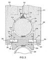
- FIG. 3 is a enlarged side-view of a roller as may be employed in accord with the present invention.
- FIG. 6 a is a top view of a plurality of offset rollers, a workpiece, and a reducing orifice that may be employed in accord with the present invention
- FIG. 6 b is a front-view of a plate having a reducing orifice as may be employed to coat a workpiece in accord with the present invention
- FIGS. 1 a and 1 b generally show a workpiece 100 surrounded by a coating assembly 102 .
- FIG. 1 a shows the assembly 102 in an open position while FIG. 1 b shows the assembly 102 in a closed position.
- the arms 106 shown in FIGS. 1 a and 1 b may be arranged to move inwardly and outwardly between the open and closed positions. The direction of movement is indicated by the arrows in FIG. 1 a .
- the arms 106 may contact the workpiece while in the open position the arms may allow the workpiece to be inserted and removed from the assembly 102 .
- One or more of the arms 106 may be moved longitudinally along the workpiece 100 by the moving member 110 . As one or more of the arms 106 move a thin film of coating may be distributed to the outside of the workpiece 100 . This thin film of coating may be supplied to the rollers 104 during the coating process from a reservoir through the fluid passages 108 .
- the rollers 104 may be shaped with a concave surface to allow a tubular workpiece to fit securely in the space defined by the rollers when they are in the closed position.
- the rollers may have other shapes as well.
- FIG. 2 a is a side sectional view of a strut 212 of a stent that has been coated in accord with the present invention.
- the strut 212 in FIG. 2 a has an inner surface 214 , an outer surface 216 , and two cut faces 218 .
- Also shown on the strut 212 is a coating 220 . As can be seen, the coating 220 , covers only one face of the strut 212 .
- the cut-out portion ( 334 a - c ) has a first section 334 a , a second section 334 b , and a third section 334 c which may communicate with one another and form a passageway.
- the first section may form a rectangle while the second section may form a socket and the third section may for a concave recess.
- a dispensing member 324 may be located within the first section 334 a while a ball 326 may be in the second section and a roller 304 may be in the third section 334 c.
- the second section 334 b forms a socket that may receive a ball 326 .
- the second section 334 b may be substantially circular or any other suitable shape and the dimensions of the second section 334 b may be slightly greater than the size of the ball 326 .
- the second section 334 b may also form two edges 335 a - b . The distance between these two edges 335 a - b may be slightly less than a diameter of the ball 326 .
- the edges 335 a - b in combination with the dimensions of the second section 334 b , maintain the ball 326 rotatably within the second section 334 b while still allowing fluid from the passage 332 to pass around the ball 326 .
- individual roller shafts 338 may be positioned on opposite sides of the roller 304 .
- the roller shaft 338 may be rotatable within the recess 336 and it may be slidable within the recess 336 as well.
- Each recess 336 may be sized to receive a biasing member 340 such as a spring.
- the roller shaft 338 may be biased inwardly by the biasing member 340 during operation.
- the dispensing member 324 may be located in the first section 334 a . As seen in FIG. 3 , coating 342 may be injected through an end of the fluid passage 332 through the dispensing member 324 . Other alternative arrangements are also plausible.
- the dispensing member 324 can be used to coat the outer surface of the ball 326 by various methods including, but not limited to needle injection, spraying, rolling, brushing, or spraying including atomized spray coating, and spray coating using an ultrasonic nozzle. In the instant case, once the coating 342 passes through the dispensing member 324 , the coating 342 may be applied to an outer surface of the ball 326 .
- the dispensing member 324 is orientated vertically and may use hydraulic pressure to facilitate delivery.
- the ball 326 may be any of a variety of shapes and sizes. In the instant case, the ball 326 is circular while in other embodiments it may contain dimples or channels of some kind.
- the size of the ball 326 and the socket 328 opening can be changed to vary the coating thickness. For example, the farther the ball 326 protrudes from the socket 328 , the more surface area the roller 304 of the ball 326 may cover.
- the dispensing member 324 dispenses coating to the ball 326 .
- the ball 326 may be interposed between the dispensing member 324 and the roller 304 to facilitate uniform coating 342 thickness.
- the ball 326 may rotate freely and, thus, roll out the coating 342 as the coating 342 is delivered from the reservoir 333 via the fluid passage 332 .
- the coating 342 may be delivered intermittently or continuously during this process.
- the ball 326 may be maintained between the dispensing member 324 and the roller 304 by the socket 328 .
- the socket 328 allows limited rotational movement of the ball 306 .
- the edges 335 a of the socket 328 may prevent more than only a portion of the ball 326 from moving outside of the socket 328 .
- the socket 328 allows the ball 326 to rotate while simultaneously acting as a seal to limit air from reaching the coating stored in the reservoir 333 and the fluid passage 332 .
- the ball 326 may rotate.
- the dispensing member 324 may deliver coating 342 to an outer surface of the ball 326 .
- FIG. 3 also shows a roller 304 in accord with the invention.
- the roller 304 may include a continuous concave shaped outer surface 344 .
- the outer surface 344 of the roller 304 can be any shape, however, preferably the roller 304 may be shaped to matingly contact the outer surface of the ball 326 .
- the coated roller 304 in turn coats the workpiece 300 .
- the arm 306 and/or the workpiece 300 can be moved to impart rotation to the ball 326 and the roller 304 .
- the arm 306 may be moved longitudinally, however, other directions are plausible.
- a target surface of the workpiece 300 may be coated. This may be accomplished by timing the dispensing of coating from the roller and the movement of the roller across the workpiece. In this example, half the outer surface of the workpiece 300 may be coated.
- FIG. 4 is a side-view of a follower mechanism 448 , an arm 406 , a dispensing member 424 , a roller 404 , a fluid passage 432 , and a workpiece 400 as may be employed in accord with the invention.
- a portion of the arm 406 may be biased via a biasing member 452 .
- the biasing member 452 can be any suitable member such as a spring.
- the biasing member 452 is configured to expand and contract to facilitate an even distribution of coating 442 on the workpiece 400 .
- a follower mechanism 448 may also be provided.
- the follower mechanism 448 may receive commands from the sensor 441 , types of which are described herein in detail. Accordingly, upon receiving a command from the sensor 441 , the follower mechanism 448 may adjustment a position of the arm 406 via a lobe 450 .
- the follower mechanism 448 may also rotate.
- the lobe 450 may be shaped so that when it rotates, the arm 406 is forced inwardly or outwardly. Consequently, the roller 404 may be adjusted by moving toward or away from the workpiece 400 .
- Other types of follower mechanisms 448 may also be used.
- the rollers are positioned at an angle to the longitudinal axis of the workpiece 500 , however, any arrangement is plausible.
- the dashed lines in FIG. 5 show a roller 504 arranged perpendicularly with respect to the longitudinal axis of the workpiece 500 .
- the edges of the reducing orifice 554 may be chamfered to facilitate the entry and exit of the workpiece 500 .
- the chamfered sections are indicated by dashed lines.
- the reducing orifice 604 can be any suitable size or shape.
- the reducing orifice 654 may be a plate with a circular hole or a tube with a predetermined diameter in accord with the embodiments.
- the reducing orifice may comprise a set of concave rollers (not shown).
- FIG. 7 shows a flowchart illustrating a method of coating a workpiece that may be employed with the present invention.
- Step 1 of the method is to provide a workpiece.
- Steps 2 and 3 of the method generally involve providing a first arm having a roller accessible from an end of the first arm and providing a second arm having a workpiece contact area accessible from an end of the second arm. Then, in Step 4, the workpiece may be positioned between the roller of the first arm and the contact area of the second arm. If desired, as illustrated in Step 5, the first arm or the second arm may be repositioned throughout the method to support the workpiece between the first arm and the second arm. As shown in Step 6, a coating may be applied from the first arm or the second arm to an exterior surface of the workpiece.
- roller, arm, reducing orifice, and dispensing member are not intended to be limiting, and any number of modifications, combinations, and alternatives of the examples may be employed to facilitate the effectiveness of the coating of target surfaces of the workpiece.
- therapeutic agents used in conjunction with the present invention include, for example, pharmaceutically active compounds, proteins, cells, oligonucleotides, ribozymes, anti-sense oligonucleotides, DNA compacting agents, gene/vector systems (i.e., any vehicle that allows for the uptake and expression of nucleic acids), nucleic acids (including, for example, recombinant nucleic acids; naked DNA, cDNA, RNA; genomic DNA, cDNA or RNA in a non-infectious vector or in a viral vector and which further may have attached peptide targeting sequences; antisense nucleic acid (RNA or DNA); and DNA chimeras which include gene sequences and encoding for ferry proteins such as membrane translocating sequences (“MTS”) and herpes simplex virus-1 (“VP22”)), and viral, liposomes and cationic and anionic polymers and neutral polymers that are selected from a number of types depending on the desired application.
- gene/vector systems i.e., any vehicle
- Non-limiting examples of virus vectors or vectors derived from viral sources include adenoviral vectors, herpes simplex vectors, papilloma vectors, adeno-associated vectors, retroviral vectors, and the like.
- Non-limiting examples of biologically active solutes include anti-thrombogenic agents such as heparin, heparin derivatives, urokinase, and PPACK (dextrophenylalanine proline arginine chloromethylketone); antioxidants such as probucol and retinoic acid; angiogenic and anti-angiogenic agents and factors; anti-proliferative agents such as enoxaprin, angiopeptin, rapamycin, angiopeptin, monoclonal antibodies capable of blocking smooth muscle cell proliferation, hirudin, and acetylsalicylic acid; anti-inflammatory agents such as dexamethasone, prednisolone, corticosterone, budesonide, estrogen, s
- Therapeutic proteins and polypeptides include as a primary example, those proteins or polypeptides that can compensate for defective or deficient species in an animal, or those that act through toxic effects to limit or remove harmful cells from the body.
- the polypeptides or proteins that can be injected, or whose DNA can be incorporated include without limitation, angiogenic factors and other molecules competent to induce angiogenesis, including acidic and basic fibroblast growth factors, vascular endothelial growth factor, hif-1, epidermal growth factor, transforming growth factor ⁇ and ⁇ , platelet-derived endothelial growth factor, platelet-derived growth factor, tumor necrosis factor ⁇ , hepatocyte growth factor and insulin like growth factor; growth factors; cell cycle inhibitors including CDK inhibitors; anti-restenosis agents, including p15, p16, p18, p19, p21, p27, p53, p57, Rb, nFkB and E2F decoys, thymidine kina
- coatings used with the exemplary embodiments of the present invention may comprise a polymeric material/drug agent matrix formed, for example, by admixing a drug agent with a liquid polymer, in the absence of a solvent, to form a liquid polymer/drug agent mixture. Curing of the mixture typically occurs in-situ.
- a cross-linking or curing agent may be added to the mixture prior to application thereof. Addition of the cross-linking or curing agent to the polymer/drug agent liquid mixture must not occur too far in advance of the application of the mixture in order to avoid over-curing of the mixture prior to application thereof.
- the polymer used to coat the medical device is provided in the form of a coating on an expandable portion of a medical device.
- the medical device After applying the drug solution to the polymer and evaporating the volatile solvent from the polymer, the medical device is inserted into a body lumen where it is positioned to a target location.
- the expandable portion of the catheter is subsequently expanded to bring the drug-impregnated polymer coating into contact with the lumen wall.
- the drug is released from the polymer as it slowly dissolves into the aqueous bodily fluids and diffuses out of the polymer. This enables administration of the drug to be site-specific, limiting the exposure of the rest of the body to the drug.
Landscapes
- Materials For Medical Uses (AREA)
- Media Introduction/Drainage Providing Device (AREA)
- Application Of Or Painting With Fluid Materials (AREA)
Priority Applications (4)
| Application Number | Priority Date | Filing Date | Title |
|---|---|---|---|
| US11/415,110 US7727598B2 (en) | 2006-05-02 | 2006-05-02 | Partially roll coated workpiece and methods and systems for making the same |
| PCT/US2007/010562 WO2007130418A2 (en) | 2006-05-02 | 2007-04-30 | Partially roll coated workpiece and methods and systems for making the same |
| EP07776577A EP2015875B1 (de) | 2006-05-02 | 2007-04-30 | Verfahren zum teilweisen beschichten eines werkstückes |
| AT07776577T ATE553852T1 (de) | 2006-05-02 | 2007-04-30 | Verfahren zum teilweisen beschichten eines werkstückes |
Applications Claiming Priority (1)
| Application Number | Priority Date | Filing Date | Title |
|---|---|---|---|
| US11/415,110 US7727598B2 (en) | 2006-05-02 | 2006-05-02 | Partially roll coated workpiece and methods and systems for making the same |
Publications (2)
| Publication Number | Publication Date |
|---|---|
| US20070259125A1 US20070259125A1 (en) | 2007-11-08 |
| US7727598B2 true US7727598B2 (en) | 2010-06-01 |
Family
ID=38654474
Family Applications (1)
| Application Number | Title | Priority Date | Filing Date |
|---|---|---|---|
| US11/415,110 Expired - Fee Related US7727598B2 (en) | 2006-05-02 | 2006-05-02 | Partially roll coated workpiece and methods and systems for making the same |
Country Status (4)
| Country | Link |
|---|---|
| US (1) | US7727598B2 (de) |
| EP (1) | EP2015875B1 (de) |
| AT (1) | ATE553852T1 (de) |
| WO (1) | WO2007130418A2 (de) |
Cited By (2)
| Publication number | Priority date | Publication date | Assignee | Title |
|---|---|---|---|---|
| US20110117266A1 (en) * | 2009-07-20 | 2011-05-19 | Boston Scientific Scimed, Inc. | Medical Device Coating System |
| US8739727B2 (en) | 2004-03-09 | 2014-06-03 | Boston Scientific Scimed, Inc. | Coated medical device and method for manufacturing the same |
Families Citing this family (7)
| Publication number | Priority date | Publication date | Assignee | Title |
|---|---|---|---|---|
| US9827401B2 (en) | 2012-06-01 | 2017-11-28 | Surmodics, Inc. | Apparatus and methods for coating medical devices |
| US11090468B2 (en) | 2012-10-25 | 2021-08-17 | Surmodics, Inc. | Apparatus and methods for coating medical devices |
| JP6445532B2 (ja) * | 2013-05-07 | 2018-12-26 | サーモディクス,インコーポレイテッド | 医療器具をコーティングするための装置および方法 |
| US11628466B2 (en) | 2018-11-29 | 2023-04-18 | Surmodics, Inc. | Apparatus and methods for coating medical devices |
| US11819590B2 (en) | 2019-05-13 | 2023-11-21 | Surmodics, Inc. | Apparatus and methods for coating medical devices |
| US12496612B2 (en) | 2021-01-08 | 2025-12-16 | Surmodics, Inc. | Coating application system and methods for coating rotatable medical devices |
| CN113262932A (zh) * | 2021-04-06 | 2021-08-17 | 中国重型机械研究院股份公司 | 辊涂机 |
Citations (12)
| Publication number | Priority date | Publication date | Assignee | Title |
|---|---|---|---|---|
| FR1427399A (fr) | 1965-03-10 | 1966-02-04 | Appareil à peindre | |
| DE8506389U1 (de) | 1985-03-06 | 1985-06-05 | Zibulla & Sohn GmbH Raziol Schmierungstechnik, 5860 Iserlohn | Vorrichtung zum Befetten von Werkstücken bei der spanlosen Umformung metallischer Werkstücke |
| DE3813939A1 (de) | 1988-04-26 | 1989-11-09 | Wolfgang Kohlmetz | Doppelrolle fuer das auftragen von anstrichmitteln |
| WO1991003331A1 (en) | 1989-08-30 | 1991-03-21 | Cleanline Corporation | Cleaning roller for surfaces and apparatus for use therewith |
| DE4105364C1 (de) | 1991-02-21 | 1992-05-27 | Zibulla & Sohn Gmbh Raziol Schmierungstechnik, 5860 Iserlohn, De | |
| US5344062A (en) | 1993-06-24 | 1994-09-06 | The Idod Trust | Method of forming seamed metal tube |
| US5830548A (en) | 1992-08-11 | 1998-11-03 | E. Khashoggi Industries, Llc | Articles of manufacture and methods for manufacturing laminate structures including inorganically filled sheets |
| JPH11138077A (ja) | 1997-09-08 | 1999-05-25 | Nkk Corp | 化成処理液の塗布装置及び塗布方法 |
| WO2003020451A1 (de) | 2001-09-04 | 2003-03-13 | Sms Demag Aktiengesellschaft | Vorrichtung zum auftragen von schmierstoffen auf die umfangsfläche von walzen in walzgerüsten |
| US20040181236A1 (en) * | 2003-03-12 | 2004-09-16 | Eidenschink Thomas C. | Methods of making medical devices |
| US6971813B2 (en) * | 2002-09-27 | 2005-12-06 | Labcoat, Ltd. | Contact coating of prostheses |
| US6984411B2 (en) | 2003-10-14 | 2006-01-10 | Boston Scientific Scimed, Inc. | Method for roll coating multiple stents |
Family Cites Families (1)
| Publication number | Priority date | Publication date | Assignee | Title |
|---|---|---|---|---|
| US5334062A (en) * | 1993-02-16 | 1994-08-02 | Fred Lurbiecki | Self-synchronizing hydraulic control systems for marine engine transmissions |
-
2006
- 2006-05-02 US US11/415,110 patent/US7727598B2/en not_active Expired - Fee Related
-
2007
- 2007-04-30 AT AT07776577T patent/ATE553852T1/de active
- 2007-04-30 WO PCT/US2007/010562 patent/WO2007130418A2/en not_active Ceased
- 2007-04-30 EP EP07776577A patent/EP2015875B1/de not_active Not-in-force
Patent Citations (13)
| Publication number | Priority date | Publication date | Assignee | Title |
|---|---|---|---|---|
| FR1427399A (fr) | 1965-03-10 | 1966-02-04 | Appareil à peindre | |
| DE8506389U1 (de) | 1985-03-06 | 1985-06-05 | Zibulla & Sohn GmbH Raziol Schmierungstechnik, 5860 Iserlohn | Vorrichtung zum Befetten von Werkstücken bei der spanlosen Umformung metallischer Werkstücke |
| DE3813939A1 (de) | 1988-04-26 | 1989-11-09 | Wolfgang Kohlmetz | Doppelrolle fuer das auftragen von anstrichmitteln |
| WO1991003331A1 (en) | 1989-08-30 | 1991-03-21 | Cleanline Corporation | Cleaning roller for surfaces and apparatus for use therewith |
| US5476546A (en) * | 1991-02-21 | 1995-12-19 | Firma Zibulla & Sohn Gmbh Raziol-Schmierungstechnik | Apparatus for applying lubricant pattern to a sheet work piece |
| DE4105364C1 (de) | 1991-02-21 | 1992-05-27 | Zibulla & Sohn Gmbh Raziol Schmierungstechnik, 5860 Iserlohn, De | |
| US5830548A (en) | 1992-08-11 | 1998-11-03 | E. Khashoggi Industries, Llc | Articles of manufacture and methods for manufacturing laminate structures including inorganically filled sheets |
| US5344062A (en) | 1993-06-24 | 1994-09-06 | The Idod Trust | Method of forming seamed metal tube |
| JPH11138077A (ja) | 1997-09-08 | 1999-05-25 | Nkk Corp | 化成処理液の塗布装置及び塗布方法 |
| WO2003020451A1 (de) | 2001-09-04 | 2003-03-13 | Sms Demag Aktiengesellschaft | Vorrichtung zum auftragen von schmierstoffen auf die umfangsfläche von walzen in walzgerüsten |
| US6971813B2 (en) * | 2002-09-27 | 2005-12-06 | Labcoat, Ltd. | Contact coating of prostheses |
| US20040181236A1 (en) * | 2003-03-12 | 2004-09-16 | Eidenschink Thomas C. | Methods of making medical devices |
| US6984411B2 (en) | 2003-10-14 | 2006-01-10 | Boston Scientific Scimed, Inc. | Method for roll coating multiple stents |
Non-Patent Citations (2)
| Title |
|---|
| International Search Report and Written Opinion in PCT/US2007/010562, dated Jan. 9, 2008. |
| Partial International Search Report in PCT/US2007/010562, dated Nov. 27, 2007. |
Cited By (2)
| Publication number | Priority date | Publication date | Assignee | Title |
|---|---|---|---|---|
| US8739727B2 (en) | 2004-03-09 | 2014-06-03 | Boston Scientific Scimed, Inc. | Coated medical device and method for manufacturing the same |
| US20110117266A1 (en) * | 2009-07-20 | 2011-05-19 | Boston Scientific Scimed, Inc. | Medical Device Coating System |
Also Published As
| Publication number | Publication date |
|---|---|
| US20070259125A1 (en) | 2007-11-08 |
| WO2007130418A3 (en) | 2008-03-13 |
| EP2015875A2 (de) | 2009-01-21 |
| EP2015875B1 (de) | 2012-04-18 |
| WO2007130418A2 (en) | 2007-11-15 |
| ATE553852T1 (de) | 2012-05-15 |
Similar Documents
| Publication | Publication Date | Title |
|---|---|---|
| EP2015875B1 (de) | Verfahren zum teilweisen beschichten eines werkstückes | |
| US7482034B2 (en) | Expandable mask stent coating method | |
| US8173200B2 (en) | Selective application of therapeutic agent to a medical device | |
| US8114466B2 (en) | Methods of applying coating to the inside surface of a stent | |
| US7335264B2 (en) | Differentially coated medical devices, system for differentially coating medical devices, and coating method | |
| US7704544B2 (en) | System and method for coating a tubular implantable medical device | |
| US7563324B1 (en) | System and method for coating an implantable medical device | |
| US9272307B2 (en) | Contact coating of prostheses | |
| US20050087520A1 (en) | Method and apparatus for selective ablation of coatings from medical devices | |
| US20050147734A1 (en) | Method and system for coating tubular medical devices | |
| US7913642B2 (en) | Film coating medical devices | |
| CA2653368A1 (en) | Coating a workpiece using a metering device and workpieces coated with this metering device | |
| WO2007145739A2 (en) | Partially coated workpieces; methods and systems for making partially coated workpieces | |
| US20050120951A1 (en) | Medical implant processing chamber | |
| US8147899B2 (en) | Methods and systems for depositing coating on a medical device | |
| US8119151B2 (en) | Spread coating a medical device | |
| US20080097569A1 (en) | Reduction of burst release from therapeutically treated medical devices | |
| US20070259116A1 (en) | Partially coated workpiece and method of making same |
Legal Events
| Date | Code | Title | Description |
|---|---|---|---|
| AS | Assignment |
Owner name: BOSTON SCIENTIFIC SCIMED, INC., MINNESOTA Free format text: ASSIGNMENT OF ASSIGNORS INTEREST;ASSIGNORS:O'BRIEN, ANTHONY;FLANAGAN, AIDEN;REEL/FRAME:017849/0426 Effective date: 20060410 Owner name: BOSTON SCIENTIFIC SCIMED, INC.,MINNESOTA Free format text: ASSIGNMENT OF ASSIGNORS INTEREST;ASSIGNORS:O'BRIEN, ANTHONY;FLANAGAN, AIDEN;REEL/FRAME:017849/0426 Effective date: 20060410 |
|
| FEPP | Fee payment procedure |
Free format text: PAYOR NUMBER ASSIGNED (ORIGINAL EVENT CODE: ASPN); ENTITY STATUS OF PATENT OWNER: LARGE ENTITY |
|
| FPAY | Fee payment |
Year of fee payment: 4 |
|
| FEPP | Fee payment procedure |
Free format text: MAINTENANCE FEE REMINDER MAILED (ORIGINAL EVENT CODE: REM.) |
|
| LAPS | Lapse for failure to pay maintenance fees |
Free format text: PATENT EXPIRED FOR FAILURE TO PAY MAINTENANCE FEES (ORIGINAL EVENT CODE: EXP.) |
|
| STCH | Information on status: patent discontinuation |
Free format text: PATENT EXPIRED DUE TO NONPAYMENT OF MAINTENANCE FEES UNDER 37 CFR 1.362 |
|
| FP | Lapsed due to failure to pay maintenance fee |
Effective date: 20180601 |