US7719524B2 - Pointing device and portable information terminal using the same - Google Patents
Pointing device and portable information terminal using the same Download PDFInfo
- Publication number
- US7719524B2 US7719524B2 US11/293,122 US29312205A US7719524B2 US 7719524 B2 US7719524 B2 US 7719524B2 US 29312205 A US29312205 A US 29312205A US 7719524 B2 US7719524 B2 US 7719524B2
- Authority
- US
- United States
- Prior art keywords
- pointing device
- image
- pointer
- fingerplate
- portable information
- Prior art date
- Legal status (The legal status is an assumption and is not a legal conclusion. Google has not performed a legal analysis and makes no representation as to the accuracy of the status listed.)
- Active, expires
Links
Images


Classifications
-
- G—PHYSICS
- G06—COMPUTING; CALCULATING OR COUNTING
- G06F—ELECTRIC DIGITAL DATA PROCESSING
- G06F3/00—Input arrangements for transferring data to be processed into a form capable of being handled by the computer; Output arrangements for transferring data from processing unit to output unit, e.g. interface arrangements
- G06F3/01—Input arrangements or combined input and output arrangements for interaction between user and computer
- G06F3/03—Arrangements for converting the position or the displacement of a member into a coded form
- G06F3/033—Pointing devices displaced or positioned by the user, e.g. mice, trackballs, pens or joysticks; Accessories therefor
- G06F3/0338—Pointing devices displaced or positioned by the user, e.g. mice, trackballs, pens or joysticks; Accessories therefor with detection of limited linear or angular displacement of an operating part of the device from a neutral position, e.g. isotonic or isometric joysticks
-
- G—PHYSICS
- G06—COMPUTING; CALCULATING OR COUNTING
- G06F—ELECTRIC DIGITAL DATA PROCESSING
- G06F3/00—Input arrangements for transferring data to be processed into a form capable of being handled by the computer; Output arrangements for transferring data from processing unit to output unit, e.g. interface arrangements
- G06F3/01—Input arrangements or combined input and output arrangements for interaction between user and computer
- G06F3/03—Arrangements for converting the position or the displacement of a member into a coded form
- G06F3/041—Digitisers, e.g. for touch screens or touch pads, characterised by the transducing means
- G06F3/042—Digitisers, e.g. for touch screens or touch pads, characterised by the transducing means by opto-electronic means
- G06F3/0421—Digitisers, e.g. for touch screens or touch pads, characterised by the transducing means by opto-electronic means by interrupting or reflecting a light beam, e.g. optical touch-screen
Definitions
- the present invention relates to a pointing device for moving a pointer (cursor) on a display screen used for a portable information terminal such as a cellular phone, and a portable information terminal using the pointing device.
- a portable information terminal such as a portable type personal computer and cellular phone has an operation panel provided with a display screen on which a pointer for pointing to a desired position of an image is displayed and a pointing device for moving this pointer to a desired position.
- a track ball that moves a pointer by detecting the rotation of a ball and a dial type pointer that moves a pointer by detecting the rotation of a disk are known.
- a cross pointer having independent feed switches for upward/downward, rightward/leftward movements of a pointer and a stick pointer used for a game machine in particular that moves a pointer by tilting a stick or disk back and forth, right and left are also known.
- a pointing device called a “track pad” which consists of a flat table shaped sensor plate with a certain area and when a finger is moved continuously on this sensor plate, the continuously changing position of the finger is detected and the pointer is moved continuously according to this detection result.
- the pointer basically moves one step by one operation, that is, the pointer moves by one item displayed on the display screen at a time, and therefore selecting an item at a considerable distance on the display screen requires more operations, which takes time and trouble.
- the track pad described above moves the pointer by touching the sensor plate with the finger and therefore the sensor plate must have an area sufficiently greater than the area of the finger that touches this and is not suited to miniaturization.
- the pointing device includes a transparent plate having an outer surface to contact the surface of an object, image detecting means for detecting an image of the surface of the object that contacts the outer surface of the plate and optical means for forming an image on the outer surface of the plate on the detection plane of the image detecting means, in which the pointer is configured to be able to move according to the movement of the image on the outer surface of the plate detected by said image detecting means.
- the portable information terminal is provided with the above-described pointing device and comprises means for detecting the movement of the image detected by the image detecting means and moving the pointer in the direction according to the direction of the detected movement.
- the above configuration allows the fingerprint of this fingertip to be detected as a moving image and allows the pointer on the display screen to move in the direction according to the direction of this movement. This prevents the user from operating different operation switches according to the moving direction of the pointer and makes the operation easier. Moreover, the user only needs to detect the movement of the image on the plate, and therefore it is possible to narrow the range of image detection and reduce the size of the pointing device.
- the above configuration makes it possible to reduce the sensing frequency of the image detecting means and suppress power consumption of the image detecting means accordingly.
- the pointing device further includes light emitting means for emitting light onto the outer surface of said plate in addition to the above configuration.
- the portable information terminal is provided with the above-described pointing device and comprises first means for measuring a reflection factor of the plate on the outer surface from the quantity of light received of the image detecting means and the quantity of light emitted of the light emitting means, second means for designating the quantity of light emitted of the light emitting means as a first reference value when the reflection factor measured by the first means falls below a predetermined minimum reference value and adjusting the quantity of light emitted of the light emitting means when the reflection factor measured by the first means exceeds the minimum reference value so that the quantity of light received by the image detecting means becomes a predetermined second reference value which is larger than the first reference value, third means for detecting the movement of the image detected by the image detecting means and moving the pointer in the direction according to the direction of said detected movement and fourth means for determining the presence/absence of movement of the image detected by the image detecting means, setting the pointing device in an action mode when the movement is detected, moving the pointer in the direction according to the direction of the movement and
- the second means changes temporarily the quantity of light emitted of the light emitting means when the reflection factor measured by the first means falls below a predetermined minimum reference value and designates the quantity of light emitted of the light emitting means as the predetermined first reference value when the quantity of light received of the image detecting means does not change as the quantity of light emitted changes.
- the light emitting means illuminates the image on the outer surface of the plate and the image detecting means can detect an image of high brightness and when no pointer movement operation is carried out without touching the outer surface of the plate with the fingertip, etc., this can be detected, which can suppress the quantity of light emitted by the light emitting means as standby mode and allows power saving.
- whether the fingertip, etc. is touching the outer surface of the plate or not is judged from the reflection factor of the image on the outer surface of the plate and further a variation of the quantity of light received of the image detecting means is detected by temporarily changing the quantity of light emitted of the light emitting means, and therefore whether the fingertip, etc. is touching the outer surface of the plate or not can be judged more accurately.
- This configuration can provide detection of an image with necessary and sufficient brightness without being affected by personal differences such as the color of the fingertip or differences from one part to another, and even if the user wears gloves, this configuration can provide detection of an image with necessary and sufficient brightness without being affected by differences in color or material.
- the portable information terminal according to the present invention in the above configuration allows the pointing device to push the plate and is provided with at least one operation switch that operates in accordance with this pushing operation and one of these operation switches is designated as an “ENTER” switch to enter the menu on the display screen indicated by the pointer.
- Such a configuration allows the pointing device to have multi-functions, makes it possible to reduce the number of operation switches on the operation panel of the portable information terminal, further reduce the size of the portable information terminal, and add new operation switches enhancing the multi-functions of the portable information terminal.
- the portable information terminal according to the present invention in the above configuration is configured so that the optical means of the pointing device can change the focal distance of the condensing lens.
- Such a configuration allows the portable information terminal according to the present invention to also have functions as a digital camera or video camera.
- FIG. 1 is a front view showing an embodiment of a portable information terminal according to the present invention
- FIGS. 2A , 2 B are configuration diagrams showing an embodiment of a pointing device according to the present invention.
- FIGS. 3A , 3 B are configuration diagrams showing another specific example of illuminating means of the pointing device shown in FIG. 2 ;
- FIGS. 4A , 4 B are configuration diagrams showing another layout example of a fingerplate of the pointing device shown in FIG. 2 ;
- FIGS. 5A , 5 B, 5 C, 5 D, 5 E, 5 F are perspective views showing a specific example of a configuration of an outer surface of the fingerplate shown in FIG. 2 to FIG. 4 ;
- FIGS. 6A , 6 B are configuration diagrams showing another specific example of the “ENTER” switch operating means shown in FIG. 2 ;
- FIGS. 7A and 7B are configuration diagrams showing another embodiment of the pointing device according to the present invention.
- FIGS. 8A , 8 B, 8 C, 8 D are configuration diagrams showing a further embodiment of the pointing device according to the present invention.
- FIGS. 9A , 9 B, 9 C, 9 D are configuration diagrams showing a still further embodiment of the pointing device according to the present invention.
- FIG. 10 is a block diagram showing a specific example of the circuit configuration of the embodiment shown in FIG. 1 ;
- FIGS. 11A , 11 B are drawings to explain a method of detecting a variation of an image picked up from the pointing device of a controller in FIG. 10 ;
- FIG. 12 is a flow chart showing an operation of the pointing device shown in FIG. 2 by the controller in FIG. 10 ;
- FIGS. 13A , 13 B, 13 C, 13 D, 13 E illustrate layout examples of the pointing device according to the present invention on a portable information terminal
- FIGS. 14A , 14 B, 14 C, 14 D, 14 E illustrate another layout examples of the pointing device according to the present invention on the portable information terminal;
- FIG. 15 is a block diagram showing a specific example of a circuit configuration of another embodiment of the portable information terminal according to the present invention.
- FIGS. 16A , 16 B, 16 C, 16 D illustrate layout examples of an open/close detector, a contact sensor, an operation lock switch, a receiver section proximity sensor shown in FIG. 15 on the portable information terminal;
- FIG. 17 is a flow chart showing a control operation of the pointing device according to detection outputs of the open/close detector, the contact sensor, the operation lock switch, the receiver section proximity sensor of the controller shown in FIG. 15 ;
- FIGS. 18A , 18 B illustrate other specific examples of misoperation preventing means of the pointing device according to the present invention
- FIGS. 19A , 19 B, 19 C illustrate further specific examples of the misoperation preventing means of the pointing device according to the present invention
- FIG. 20 is a flow chart showing a specific example of an operation procedure for making a call with the embodiment of the portable information terminal according to the present invention.
- FIGS. 21A , 21 B, 21 C, 21 D, 21 E, 21 F, 21 G illustrate specific examples of screens displayed sequentially on the display screen according to the operation procedure shown in FIG. 20 ;
- FIG. 22 is a flow chart showing a specific example of the operation procedure for receiving a map service of the embodiment of the portable information terminal according to the present invention.
- FIGS. 23A , 23 B, 23 C, 23 D, 23 E, 23 F, 23 G, 23 H, 23 I, 23 J illustrate specific examples of the screens displayed sequentially on the display screen shown in FIG. 22 ;
- FIGS. 24A , 24 B are cross-sectional views showing a specific example of the pointing device when the embodiment of the portable information terminal according to the present invention is provided with a video camera function.
- FIG. 1 is a front view showing an embodiment of a portable information terminal using a pointing device according to the present invention.
- Reference numeral 1 denotes a portable information terminal; 2 , an operation panel; 2 a , a “Power/stop call” button; 2 b , “Start call” button; 2 c , a “Menu” button; 2 d , a “Return” button; 3 , a display screen; 4 , a pointing device.
- this embodiment shows a case of a cellular phone, but this embodiment can also be other portable information terminals such as a portable type personal computer.
- the operation panel 2 including various operation components such as the pointing device 4 and the display screen 3 that shows an image and pointer (cursor, not shown) are provided on the front of the portable information terminal 1 .
- the operation panel 2 is provided with the “Power/stop call” button 2 a to indicate the power button and the end of a call, the Start call” button 2 b to indicate the start of a call, the “Menu” button 2 c to display the menu screen on the display screen 3 , the “Return” button 2 d to return to the screen displayed just before on the display screen 3 and a ten-key pad which can also be used to enter characters, etc.
- the pointer displayed on the display screen 3 can be moved by stroking the surface of the pointing device 4 on the operation panel 2 with a fingertip.
- the pointing device 4 is also provided with an enter function which is not shown and pressing this pointing device 4 with the fingertip activates this enter function to enter an item indicated by the pointer on the display screen 3 or touch button, etc.
- FIG. 2 shows an embodiment of the pointing device 4 according to the present invention used for the portable information terminal shown in FIG. 1 and FIG. 2A is a vertical cross-sectional view and FIG. 2B is a top view to see through the pointing device 4 and reference numeral 4 a denotes a fingerplate; 4 b , a light emitting device; 4 c , an image pick-up element; 4 d , a condensing lens; 4 e , a hinge; 5 , “ENTER” switch, 6 , a circuit board; 7 , a fingertip; 7 a , the thick of the fingertip; 8 , an outer case of the portable information terminal 1 , 8 a , a through hole perforated in the outer case 8 .
- 4 a denotes a fingerplate
- 4 b a light emitting device
- 4 c an image pick-up element
- 4 d a condensing lens
- 4 e a hinge
- 5 “ENTER” switch,
- the top surface of the outer case 8 in FIG. 2A is an outside of the portable information terminal 1 .
- the fingerplate 4 a , light emitting device 4 b , image pick-up element 4 c , condensing lens 4 d and hinge 4 e constitute the pointing device 4 in FIG. 1 and the transparent fingerplate 4 a of these components is fitted in the through hole 8 a perforated in the outer case 8 on the operation panel 2 ( FIG. 1 ) side of the portable information terminal 1 .
- This fingerplate 4 a has a convex outer surface (that is, the surface of the fingertip 7 shown in the figure) and sticks out of the outer surface of the outer case 8 and can be easily touched by the thick 7 a of the fingertip 7 .
- this fingerplate 4 a is supported by the hinge 4 e and set in such a way as to be pivotable centered on the hinge 4 e in the direction shown by the arrow.
- This fingerplate 4 a can be pushed in the outer case 8 (that is, inside the portable information terminal 1 ) by the fingertip 7 .
- the fingerplate 4 a is returned to its original position shown in the figure by restoring means such as a spring (not shown).
- the light emitting device 4 b condensing lens 4 d and image pick-up element 4 c are provided inside the outer case 8 .
- the image pick-up element 4 c is fixed to the circuit board 6 inside the outer case 8 .
- the normal in the center of the image pick-up surface of this image pick-up element 4 c , the optical axis of the condensing lens 4 d and the central axis of the fingerplate 4 a almost coincide and the condensing lens 4 d is placed in such a way that the image of the object on the outer surface of the fingerplate 4 a is focused on the image pick-up surface of the image pick-up element 4 c .
- the light emitting device 4 b irradiates diagonally the outer surface of the fingerplate 4 a from the inside of the outer case 8 . Therefore, when there is nothing on the outer surface of the fingerplate 4 a , the light beam from the light emitting device 4 b passes through the fingerplate 4 a and goes out of the portable information terminal 1 , but if the thick 7 a of the fingertip 7 touches the outer surface of the fingerplate 4 a , the light beam from the light emitting device 4 b illuminates this thick 7 a and part of the reflected light is collected by the image pick-up element 4 c via the condensing lens 4 d .
- the image of the finger print is taken by the image pick-up element 4 c .
- the image pick-up area of this image pick-up element 4 c on the fingerplate 4 a is part of the area such as the central area of the fingerplate 4 a , and therefore an image of part of the area of the thick 7 a of the fingertip 7 that touches the fingerplate 4 a is picked up.
- the pattern of this surface of the object is a pattern made up of projections and depressions such as the finger print of the fingertip 7 , the variations of light and shade produced by this light beam becomes further noticeable and an image with a more distinctive pattern is picked up by the image pick-up element 4 c.
- the fingerplate 4 a touches and activates the “ENTER” switch 5 to carry out an enter operation, which will be described later.
- FIG. 3 is a block diagram showing another specific example of the illuminating means of the pointing device 4 shown in FIG. 2 and reference numerals 4 f , 4 f 1 and 4 f 2 denote optical path changing means and the same parts as those in FIG. 2 are assigned the same reference numerals and overlapping explanations will be omitted.
- FIG. 3A A specific example shown in FIG. 3A describes a case where the light emitting device 4 b is placed on the circuit board 6 face up (that is, the outgoing illumination beam is oriented perpendicular to the plane of the circuit board 6 ) and the illumination beam is emitted in the direction perpendicular to the plane of the circuit board 6 .
- the optical path changing means 4 f made up of a mirror or prism is provided between this light emitting device 4 b and the outer case 8 so that the optical path changing means 4 f changes the optical path of the illumination beam output from the light emitting device 4 b and the fingerplate 4 a is irradiated with this illumination beam diagonally from the lower part.
- FIG. 3B A specific example shown in FIG. 3B describes a case where the light emitting device 4 b is placed on its side on the circuit board 6 (that is, the outgoing beam is oriented parallel to the surface of the circuit board 6 ) and the illumination beam is emitted in the direction parallel to the surface of the circuit board 6 .
- an optical path changing means 4 f 1 made up of a mirror or prism is provided facing the light emission port of this light emitting device 4 b and an optical path changing means 4 f 2 made up of a mirror or prism is provided facing the optical path changing means 4 f 1 between the circuit board 6 and outer case 8 so that the light path of the illumination beam output from the light emitting device 4 b is changed by these optical path changing means 4 f 1 and 4 f 2 and the fingerplate 4 a is irradiated with this illumination beam diagonally from below.
- placing the light emitting device 4 b which is an electronic part, on the same circuit board as that of the image pick-up element 4 c can simplify wiring support parts, etc., reduce manufacturing cost and shorten the operation time.
- FIG. 4 is a configuration diagram showing another layout of the fingerplate 4 a of the pointing device 4 shown in FIG. 2 and the same parts as those in FIG. 2 are assigned the same reference numerals and overlapping explanations will be omitted.
- FIG. 4A The specific example shown in FIG. 4A is configured to allow the fingerplate 4 a to be placed inside the outer case 8 .
- the entire fingerplate 4 a can be placed inside the outer case 8 or the fingerplate 4 a can be placed so that the central part of the convex outer surface of the fingerplate 4 a is placed inside the through hole 8 a of the outer case 8 or the central part of the convex outer surface of the fingerplate 4 a sticks out of this through hole 8 a.
- the distance between the fingerplate 4 a and circuit board 6 becomes shorter, and therefore it is possible to increase the above distance by making the thickness of the fingerplate 4 a almost uniform and make the inner surface side have a concave shape.
- FIG. 4B The specific example shown in FIG. 4B is configured in such a way that the fingerplate 4 a is placed outside the outer case 8 .
- the “ENTER” switch 5 is also mounted on the outer case 8 so that at least the operation part pressed by the fingerplate 4 a also comes outside the outer case 8 .
- FIG. 5 is a perspective view showing specific examples of configurations of the outer surface of the fingerplate 4 a shown in FIG. 2 to FIG. 4 .
- the fingerplate 4 a has a true circle shape, but the present invention is not limited to this and any surface shape can be taken such as ellipsoidal, rectangular or other shapes.
- FIG. 5A shows the fingerplate 4 a whose outer region is made up of an opaque outline section 10 and has a transparent section 9 inside this outline section 10 as the area through which light passes.
- the image pick-up element 4 c uses a predetermined area of this transparent section 9 as the image pick-up area.
- Such outline section 10 can reduce unnecessary incident light toward the image pick-up surface of the image pick-up element 4 c from outside.
- FIG. 5B shows the fingerplate 4 a with a shallow groove-like guide 11 provided in the radial direction passing its center, which makes it easier to move the fingertip 7 ( FIG. 2 ) while touching the fingerplate 4 a . It is this central part within this guide 11 that is the image pick-up area of the image pick-up element 4 c and the area outside this image pick-up area can be opaque.
- the guide 11 is provided only in one direction, but as shown in FIG. 5C , it is also possible to provide two guides 11 a and 11 b , which intersect at right angles. In this case, the image pick-up area 12 of the image pick-up element 4 c is set at the intersection of these guides 11 a and 11 b.
- FIG. 5D shows the specific example in FIG. 5C with guides 11 a and 11 b further finished with a gloss and the other area 13 leather-grained. Applying leather-graining to this area 13 has an effect of making it easier to slide the finger and preventing sweat from sticking to the surface.
- FIG. 5E shows a case where a hollow section 14 is provided in the center of the outer surface of the fingerplate 4 a and the image pick-up area of the image pick-up element 4 c is set within this hollow section 14 .
- Setting the image pick-up area of the image pick-up element 4 c within this hollow section 14 in this way prevents other objects from touching this image pick-up area and prevents this image pick-up area from being damaged when the portable information terminal 1 is put in, for example, a briefcase.
- FIG. 6 illustrates another specific example of the operating means of the “ENTER” switch 5 shown in FIG. 2 and the same parts as those in FIG. 2 are assigned the same reference numerals and overlapping explanations thereof will be omitted.
- FIG. 6A shows a case where the fingerplate 4 a is attached to the inner surface of the outer case 8 via the hinge 4 e at a sufficiently large distance from the through hole 8 a provided in the outer case 8 .
- This makes it possible to increase a distance L between the position on the fingerplate 4 a pressed by the fingertip to carry out an ENTER operation and the position at which this fingerplate 4 a is attached to the outer case 8 and realize a motion close to a pushing operation in the vertical direction though it is actually an arc-shaped motion centered on the hinge 4 e.
- FIG. 6B shows a case where the fingerplate 4 a is attached to the inner surface of the outer case 8 via the hinge 4 e at a position close to the through hole 8 a provided in the outer case 8 and at the same time this fingerplate 4 a extends beyond the position at which the fingerplate 4 a is attached via this hinge 4 e and the “ENTER” switch 5 is provided on the line of this extension.
- the “ENTER” switch 5 is lifted centered on the mounting section via the hinge 4 e and the operating part thereof is pressed against the inner surface of the outer case 8 to perform an ENTER operation.
- the ENTER operation can be performed with a smaller force by applying the principle of leverage though this depends on a positional relationship between the hinge 4 e and the “ENTER” switch 5 .
- FIG. 7 is a configuration diagram showing another embodiment of the pointing device 4 according to the present invention.
- FIG. 7A is a top view and FIG. 7B is a cross-sectional view.
- Reference numeral 15 denotes a “RETURN” switch
- 16 a and 16 b denote protrusions
- reference numeral 17 denotes a rotation axis.
- the same parts as those in the above-described figures are assigned the same reference numerals and overlapping explanations thereof will be omitted.
- This embodiment describes a case where the pointing device 4 described in FIG. 2 to FIG. 4 is provided with enhanced multi-functions.
- the “ENTER” switch 5 and “RETURN” switch 15 are placed inside the outer case 8 with the through hole 8 a placed in between and protruding pressing sections are formed toward the switches 5 and 15 on the fingerplate 4 a .
- the fingerplate 4 a is placed by mounting means (not shown) in such a way as to be pivotable centered on the rotation axis 17 .
- the rotation axis 17 is perpendicular to the straight line connecting the “ENTER” switch 5 and “RETURN” switch 15 .
- the mounting means above is made of a transparent material or provided in such a way as to bypass the image pick-up area so as not to prevent the image pick-up element 4 c ( FIG.
- a protrusion 16 a and a protrusion 16 b are provided toward the “RETURN” switch 15 and toward the “ENTER” switch 5 of the outer surface of the fingerplate 4 a , respectively.
- the image pick-up area of the image pick-up element 4 c on the outer surface of this fingerplate 4 a is the central part between the protrusions 16 a and 16 b on this outer surface.
- the image in the image pick-up area on the outer surface of the fingerplate 4 a is taken by the image pick-up element 4 c and pushing in the “ENTER” switch 5 of this fingerplate 4 a with the fingertip causes the protruding pressing section of this fingerplate 4 a to press and activate this “ENTER” switch 5 to carry out an ENTER operation.
- the fingertip is stopped by the protrusion 16 b , which makes it easier to push in the ENTER” switch 5 of the fingerplate 4 a .
- this embodiment also describes the case where the pointer displayed on the display screen 3 is moved continuously or step by step by touching and moving the image pick-up area in the center of the fingerplate 4 a with the fingertip (the pointer moves continuously when moving on a map and moves step by step when moving on the screen of a selection item such as a menu screen). Furthermore, the protrusions 16 a and 16 b are not always necessary.
- FIG. 8 is a configuration diagram showing a further embodiment of the pointing device 4 according to the present invention and FIG. 8A is a top view, FIG. 8B is a cross-sectional view and FIG. 8C and FIG. 8D are functional schematic diagrams, and reference numerals 17 a and 17 b denote rotation axes; 18 a to 18 d , functional switches; and 19 , protrusions.
- reference numerals 17 a and 17 b denote rotation axes; 18 a to 18 d , functional switches; and 19 , protrusions.
- the same parts as those shown in the above-described drawings are assigned the same reference numerals and overlapping explanations thereof will be omitted.
- This embodiment describes the pointing device 4 explained in FIG. 2 to FIG. 4 with enhanced multi-functions.
- FIG. 8A and FIG. 8B four functional switches 18 a , 18 b , 18 c and 18 d are spaced uniformly around the through hole 8 a of the outer case 8 inside the outer case 8 and protruding pressing sections corresponding to these functional switches 18 a , 18 b , 18 c and 18 d are formed on the fingerplate 4 a.
- the fingerplate 4 a is placed by mounting means (not shown) in such a way as to be pivotable on the two axes of the rotation axes 17 a and 17 b orthogonal, which are perpendicular to each other.
- the rotation axis 17 a is perpendicular to the straight line connecting the functional switches 18 c and 18 d
- the rotation axis 17 b is perpendicular to the straight line connecting the functional switches 18 a and 18 b
- the mounting means above of the fingerplate 4 a is made of a transparent material so as not to prevent the image pick-up element 4 c ( FIG. 2 ) from capturing the image on the outer surface of the fingerplate 4 a .
- protrusions 19 are provided toward the functional switches 18 a to 18 d on the outer surface of the fingerplate 4 a .
- the image pick-up area of the image pick-up element 4 c on the outer surface of this fingerplate 4 a is the central part between the protrusions 19 on this outer surface.
- the image of the above-described image pick-up area on the outer surface of the fingerplate 4 a is taken by the image pick-up element 4 c and pressing the functional switch 18 a side of this fingerplate 4 a with the fingertip causes the fingerplate 4 a to incline toward the functional switch 18 a and the protruding pressing section of the fingerplate 4 a presses and activates the functional switch 18 a .
- the protrusion 19 is provided on the functional switch 18 a side of the outer surface of the fingerplate 4 a , the fingertip is stopped by this protrusion, which makes it easier to push in the functional switch 18 a side of the fingerplate 4 a .
- the functional switches 18 a to 18 d are provided with predetermined functions.
- FIG. 8C shows an example of this.
- the functional switches 18 a to 18 d are provided with the function of moving the pointer displayed on the display screen 3 ( FIG. 1 ) one step at a time (that is, one item at a time when the menu screen is displayed on the display screen 3 ). More specifically, explaining this with reference to FIG. 8A , the functional switch 18 a is used to move the pointer one step rightward at a time, the functional switch 18 b is used to move the pointer one step leftward, the functional switch 18 c is used to move the pointer one step upward and the functional switch 18 d is used to move the pointer one step downward.
- FIG. 8D shows another example of function.
- the portable information terminal 1 provided with the pointing device 4 with the image pick-up element 4 c ( FIG. 2 ) and the display screen 3 can function as a video camera to take pictures of landscapes, etc. using the image pick-up element 4 c and store signals of images taken by the image pick-up element 4 c in a built-in storage device with an increased volume of storage or in a large-volume storage medium that can be attached to the apparatus and read and replay the image signals on the display screen 3 .
- the functional switch 18 a is provided with a fast-forward function
- the functional switch 18 b is provided with a rewind function
- the functional switch 18 c is provided with a replay/pause function
- the functional switch 18 d is provided with a stop function.
- touching the image pick-up area in the central part of the fingerplate 4 a with the fingertip and moving the fingertip allows the pointer displayed on the display screen 3 to move continuously or step by step (the pointer moves continuously when moving on a map and moves step by step when moving on the screen of a selection item such as a menu screen).
- the protrusions 19 are not always necessary.
- FIG. 9 is a configuration diagram showing another embodiment of the pointing device 4 according to the present invention and FIG. 9A is a top view, FIG. 9B and FIG. 9C are cross-sectional views along a line A-A′ and B-B′ of FIG. 9A , respectively and FIG. 9D is a functional schematic diagram.
- Reference numeral 20 denotes an ENTER operation section; 21 , a functional operation section; 22 , an actuating part; 23 , a hinge.
- the same parts as those in FIG. 8 are assigned the same reference numerals and overlapping explanations thereof will be omitted.
- This embodiment is a case where an ENTER operation section is added to the pointing device 4 explained in FIG. 8 to further enhance the multi-functions.
- the fingerplate 4 a is divided into two areas; a central part and a peripheral part and the central part constitutes an ENTER operation section 20 and the peripheral part constitutes a functional operation section 21 to activate the functional switches 18 a to 18 d . Since this functional operation section 21 is similar to the fingerplate 4 a in the embodiment shown in FIG. 8 , explanations thereof will be omitted.
- the ENTER operation section 20 is configured to be able to be pushed in.
- One end of the actuating part 22 which is supported by a hinge 23 in a pivotable manner, is attached to the inner side of this ENTER operation section 20 and the other end of this actuating part 22 constitutes the operation section of the “ENTER” switch 5 provided on the inner surface of the outer case 8 .
- Pushing in the ENTER operation section 20 of the fingerplate 4 a with the fingertip makes the actuating part 22 rotate centered on the hinge 23 and the operation part at the end of this actuating part 22 acts on the “ENTER” switch 5 and activates it.
- the ENTER operation section 20 returns to its original position by means which is not shown.
- the image pick-up area of the image pick-up element 4 c ( FIG. 2 ) is set inside the ENTER operation section 20 in this embodiment, too and touching this image pick-up area with the fingertip and moving the fingertip allows the pointer displayed on the display screen 3 to move continuously.
- FIG. 10 is a block diagram showing a circuit configuration of the portable information terminal 1 shown in FIG. 1 and reference numeral 24 denotes an antenna; 25 , radio equipment that transmits/receives a radio signal; 26 , a modulator/demodulator that modulates a transmission signal and demodulates a received signal; 27 , a transmission/reception signal processor that processes a transmission signal or arriving signal; 28 , a sound processor that processes a speech signal from a speech transmitter 29 such as a microphone and a speech signal supplied to a speech receiver 30 such as a speaker; 31 , a controller that controls the entire portable information terminal 1 ; 32 , a storage device that stores information from a telephone directory, various set data or information from the Internet; 33 , a display that displays images or pointer, etc. on the display screen 3 ( FIG. 1 ); 34 , a silent arrival annunciator such as a vibrator that produces vibration to notify the user of arrival of a call and the same parts as those in FIG. 1 are assigned the same reference
- the controller 31 reads image signals from this image pick-up element 4 c at predetermined time intervals, compares images of image signals loaded before and after, such as time t 1 and time t 2 as shown in FIG. 11 , detects a change and thereby detects the movement of the fingertip 7 on the pointing device 4 . Then, this controller 31 controls the position of the pointer displayed on the display screen 3 ( FIG. 1 ) by the display 33 according to this detection result.
- the controller 31 When no movement of the fingertip 7 is detected, the controller 31 holds this pointer in a halt state and when any movement of the fingertip 7 is detected, the controller 31 moves the pointer at a speed according to the movement of this fingertip 7 and in the direction according to the direction of the movement of this fingertip 7 .
- touching the fingerplate 4 a of the pointing device 4 with the fingertip 7 and moving this fingertip 7 allows the pointer to move on the display screen 3 .
- the pointer when the pointer reaches a predetermined position on the display screen 3 (for example, a position at which a predetermined item is displayed), pushing in the fingerplate 4 a with the fingertip 7 activates the “ENTER” switch 5 and selects and specifies the position (for example, the predetermined item above).
- a predetermined position on the display screen 3 for example, a position at which a predetermined item is displayed
- the controller 31 detects the quantity of light received by the image pick-up element 4 c of the pointing device 4 and controls the quantity of light emitted by the light emitting device 4 b , etc.
- Parts other than those described above are the same as those in the conventional portable information terminal.
- FIG. 12 is a flow chart showing a control operation of the pointing device 4 by the controller 31 .
- the pointing device 4 when the “Power/stop call” button 2 a is operated on the operation panel 2 of the portable information terminal 1 shown in FIG. 1 , power is turned on, or when the pointing device 4 gets ready for operation by opening the cover of the portable information terminal 1 in a configuration described later, or unfolding the folded portable information terminal 1 , the pointing device 4 is set in a standby mode (step 100 ).
- the controller 31 makes the light emitting device 4 b emit illumination light with a predetermined quantity of light emission and the image pick-up element 4 c repeats picture taking with the frequency (sensing frequency) of approximately 10 times a second.
- the quantity of light received is assumed to be, for example, the integrated value of the output signal value corresponding to one screen from the image pick-up element 4 c and the quantity of light emitted of the light emitting device 4 b is assumed to be a drive power value of this light emitting device 4 b.
- this reflection factor calculated is compared with a preset minimum reflection factor (minimum reference value) (step 102 ).
- This step 102 is intended to determine whether the fingertip 7 , etc. is touching the fingerplate 4 a or not and this minimum reference value can be obtained by, for example, an experiment, etc.
- step 101 if the reflection factor obtained in step 101 is below this minimum reference value, it is determined that the fingertip, etc. is not touching the fingerplate 4 a for the operation of moving the pointer on the display screen 3 (hereinafter referred to as “pointer operation”) (if the reflection factor is below this minimum reference value, the quantity of light emitted of the light emitting device 4 b is temporarily increased and the quantity of light received by the image pick-up element 4 c at this time is detected, and if there is almost no change in the quantity of light received even if the quantity of light emitted is increased in this way, it can also be determined that the fingertip, etc.
- pointer operation if the reflection factor is below this minimum reference value, the quantity of light emitted of the light emitting device 4 b is temporarily increased and the quantity of light received by the image pick-up element 4 c at this time is detected, and if there is almost no change in the quantity of light received even if the quantity of light emitted is increased in this way, it can also be determined that the finger
- step 103 the quantity of light emitted of the light emitting device 4 b is set to a preset small reference value (step 103 ) and the process moves on to step 105 .
- step 103 the quantity of light emitted of the light emitting device 4 b is set to a preset small reference value (step 103 ) and the process moves on to step 105 .
- step 104 the quantity of light emitted of the light emitting device 4 b is set to a value according to this reflection factor and the quantity of light received by the image pick-up element 4 c is adjusted to a predetermined constant value (step 104 ).
- the quantity of light emitted of the light emitting device 4 b is increased so as to increase the output level of the image pick-up element 4 c , or on the contrary, if the reflection factor of the fingertip 7 touching the fingerplate 4 a is high and the quantity of light received on the image pick-up surface by the image pick-up element 4 c is too much, the quantity of light emitted of the light emitting device 4 b is decreased so that the light emitting device 4 b does not output the quantity of unnecessary light to save power consumption. After this quantity of light emitted is adjusted, the process moves on to step 105 .
- the image pick-up element 4 c takes pictures with low frequency in a standby mode (that is, sensing frequency is 10 times/sec, etc.), and every time an image is taken, the image pick-up element 4 c compares the image with the previous image and detects whether there is any change (movement) of the image. Then, if no change is detected for one sec or more (step 106 ), unless the “Power/stop call” button 2 a ( FIG. 1 ) on the operation panel 2 is operated again and power is turned off (step 110 ), the process returns to step 100 and detects the reflection factor as shown above and adjusts the quantity of light emitted of the light emitting device 4 b .
- the pointing device 4 is set in a halt state.
- step 107 the sensing frequency of the image pick-up element 4 c is set to a high speed, for example, 1000 times/sec, and this makes smooth the change of the image obtained from the image pick-up element 4 c for the movement of the fingertip 7 .
- the controller 31 picks up each image taken and detects a change from the image taken previously and changes the position of the pointer according to the change, that is, the movement of the fingertip 7 (step 108 ).
- the operations in step 107 and 108 are repeated as long as such an operation of the pointing device 4 continues (step 109 ).
- the image pick-up element 4 c takes pictures (sensing) with a frequency as high as 1000 times a second, for example, compared to a normal video camera, but since the picture taking range of this image pick-up element 4 c is extremely narrow, detection of images can be performed with high resolution even if the number of pixels is set to a small value compared to an image pick-up element used for an ordinary video camera, and this ability to reduce the number of pixels makes it possible to increase the sensing frequency as shown above.
- the quantity of light emitted of the light emitting device 4 b is reduced (step 103 ) and the sensing frequency of the image pick-up element 4 c is reduced considerably compared to the action mode (step 100 ), and it is therefore possible to suppress power consumption considerably, and even if the fingertip 7 , etc. is touching the fingerplate 4 a , the sensing frequency of the image pick-up element 4 c is reduced considerably (step 100 ), which makes it possible to expect suppression of power consumption.
- the fingertip 7 moves and an action mode starts almost immediately in that condition, and therefore, it is rather more important to adjust the quantity of light emitted of the light emitting device 4 b (step 104 ), move the fingertip 7 and transition to the action mode immediately.
- step 109 when an ENTER operation is performed by pushing in the fingerplate 4 a of the pointing device 4 with the fingertip 7 or when the operation of the pointing device 4 is finished by operating the operation switches other than the pointing device 4 (step 109 ), unless the “Power/stop call” button 2 a ( FIG. 1 ) on the operation panel 2 is operated and power is turned OFF or the use of the portable information terminal 1 is finished by putting the cover to the portable information terminal 1 , which will be described later (step 110 ), the process returns to step 100 and starts the operation from there and the pointing device 4 is set in a standby state until it is operated next.
- FIG. 13 illustrates layout examples of the pointing device 4 in the embodiment of this portable information terminal 1 and FIG. 13A shows an example of placing the pointing device 4 on the operation panel 2 , FIG. 13B shows an example of placing the pointing device 4 on the back 1 a of portable information terminal 1 , FIG. 13C shows an example of placing the pointing device 4 on one side 1 b of the portable information terminal 1 (here, the pointing device 4 is placed on the side 1 b , but can also be placed on the opposite side 1 b ) and FIG. 13D shows an example of placing the pointing device 4 next to the display screen 3 . Moreover, a specific example in FIG. 13E shows an embodiment in which numerical keys to enter telephone numbers are eliminated and numbers are entered only through operations of the pointing device.
- a number list and a pointer are displayed in the peripheral section of the display screen 3 and it is possible to enter a number by moving the pointer to the number to be entered using the pointing device 4 and performing an ENTER operation. With such a portable information terminal 1 , it is also possible to place the pointing device 4 at an appropriate position.
- the pointing device 4 can be placed in any location of the portable information terminal 1 taking into account the ease of operation, etc.
- the layout examples shown in FIG. 13B and FIG. 13C most areas of the back 1 a and side 1 b of the portable information terminal 1 are not used and placing the pointing device 4 in easy-to-use locations makes it possible to effectively use the surface of the portable information terminal 1 , reduce the size of the operation panel and implement a further reduction in size of the portable information terminal 1 .
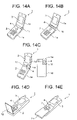
- FIG. 14 illustrates layout examples of the pointing device 4 of another embodiment of the portable information terminal 1 .
- FIG. 14A to FIG. 14C relate to a folding portable information terminal 1 in which a case 1 d provided with the display screen 3 is connected with a case 1 e having the operation panel 2 in a pivotable manner by a hinge 1 c and when the portable information terminal is not used, overlapping the case 1 d over the case 1 e makes it possible to prevent the display screen 3 and operation panel 2 from exposing to the outside.
- the specific example in FIG. 14A shows the pointing device 4 placed on the operation panel 2 and the specific example in FIG. 14B shows the pointing device 4 placed on a hinge 1 c .
- the pointing device 4 placed on the operation panel 2 , it is possible to protect the pointing device 4 when the portable information terminal 1 is not used.
- FIG. 14C shows a case where the case 1 d is provided with a notch section 1 f facing the case 1 e so that part of the case 1 e is exposed to the outside through this notch section 1 f also when the terminal is folded and the pointing device 4 is placed in that exposed section.
- a function different from the original function that is, the function of moving the pointer on the display screen 3 , that is, pointer operation function
- Such a function can be a function of display of arrival, etc. allowing the light emitting device 4 b of the pointing device 4 ( FIG. 2 ) to emit light when there is an incoming call while the terminal is folded.
- FIG. 14D shows a case where a flip (open/close cover) 1 g is provided on the operation panel 2 and the specific example shown in FIG. 14E shows a case where a slide cover 1 h is provided on the operation panel 2 .
- the pointing device 4 performs the operation shown in FIG. 12 and when the terminal is folded in the specific examples in FIG. 14A to FIG. 14C , or when the covers 1 g and 1 h are closed in the specific examples in FIG. 14D and FIG. 14E , it is determined in step 110 that the portable information terminal 1 has finished the operation and the pointing device 4 is set in a halt state. Furthermore, when the terminal is unfolded in the specific examples in FIG. 14A to FIG. 14C , or when the covers 1 g and 1 h are opened in the specific examples in FIG. 14D and FIG. 14E , the pointing device 4 starts to operate in the standby mode in step 100 . In this case, it goes without saying that a sensor (not shown) to detect the folding state or the open/closed state of the covers 1 g and 1 h is provided in each portable information terminal 1 shown in FIG. 14 .
- the pointing device 4 is placed at an appropriate location of the portable information terminal 1 , and it goes without saying that the location is the one which allows the user to easily operate the portable information terminal 1 by the thumb or forefinger when the user holds the portable information terminal 1 by hand.
- the location is the one which allows the user to easily operate the portable information terminal 1 by the thumb or forefinger when the user holds the portable information terminal 1 by hand.
- FIG. 15 is a block diagram showing a circuit configuration of another embodiment of the portable information terminal.
- Reference numeral 35 denotes an open/close detector; 36 , a contact sensor; 37 , an operation lock switch; 38 , a receiver section proximity sensor, and the same parts as those in FIG. 2 will be assigned the same reference numerals and overlapping explanations thereof will be omitted.
- This embodiment in FIG. 15 is the circuit configuration shown in FIG. 2 with all or at least one of the open/close detector 35 , contact sensor 36 , operation lock switch 37 and receiver section proximity sensor 38 .
- the open/close detector 35 is provided for the portable information terminal 1 of a folded type or with the cover as shown in FIG. 15 .
- the open/close detector 35 is placed on either the surface of the case 1 d or 1 e (here, the side next to the display screen 3 of the case 1 d ).
- This open/close detector 35 can be a push-type switch or optical sensor.
- the open/close detector 35 detects this and supplies this detection output to the controller 31 .
- the controller 31 determines whether the portable information terminal 1 is opened or not in the case of the folded type portable information terminal 1 and whether the cover is opened or closed in the case of the portable information terminal 1 with a cover.
- the contact sensor 36 is placed on the side 1 b of the portable information terminal 1 to detect whether the palm of the hand of the user touches or not, as shown in FIG. 16B . This detected output is supplied to the controller 31 and the controller 31 determines from this detected output whether the portable information terminal 1 is held by the hand of the user or not.
- This contact sensor 36 can be placed on one side 1 b of the portable information terminal 1 or can also be placed on both sides of the portable information terminal 1 .
- the contact sensor 36 of an electrostatic capacitive type capable of distinguishing the human hand from other objects when the sensor is placed on one side 1 b or a type of contact sensor 36 using the electrical resistance value of the human hand as a detection reference when the sensor is placed on both sides.
- the operation lock switch 37 is provided on one side 1 b of the portable information terminal 1 as shown in FIG. 16C and operating the operation lock switch 37 locks the operation switches on the operation panel 2 and pointing device 4 preventing them from operating.
- the receiver section proximity sensor 38 is placed close to the location of the sound receiver 30 such as a speaker of the portable information terminal 1 as shown in FIG. 16D to detect any object that approaches this (for example, within a range of 1 cm) and send the detected output to the controller 31 .
- the controller 31 determines from this detected output that the ear of the user approaches the sound receiver 30 and determines that a call is being received.
- FIG. 17 is a flow chart showing the control operation of the controller 31 in response to detected outputs from the open/close detector 35 , contact sensor 36 , operation lock switch 37 and receiver section proximity sensor 38 .
- this flow chart will be explained assuming that the portable information terminal 1 is provided with all or some of these open/close detector 35 , contact sensor 36 , operation lock switch 37 and receiver section proximity sensor 38 .
- step 201 in the case of portable information terminal 1 as shown in FIG. 16C , if the operation lock switch 37 is ON (step 201 ), the operation switches on the operation panel 2 are locked so that they cannot be operated, and at this time the controller 31 sets the pointing device 4 in a halt state (that is, the light emitting device 4 b and image pick-up element 4 c in FIG. 2 are not operating. Step 200 ). Furthermore, in the case of the folded type portable information terminal 1 as shown in FIG. 16A , if the cases 1 d and 1 e overlap with each other in a folded state, the open/close detector 35 is in an open state (step 202 ) and the controller 31 also sets the pointing device 4 in a halt state (step 200 ).
- this receiver section proximity sensor 38 supplies a detected output indicating that the user's ear is close to the sound receiver 30 and a conversation is in progress to the controller 31 (step 203 ) and the controller 31 sets the pointing device 4 in a halt state (step 200 ).
- the controller 31 determines from the detected output from this contact sensor 36 that the portable information terminal 1 is not held by the hand of the user and is not used and sets the pointing device 4 in a halt state (step 200 ).
- the pointing device 4 when it is detected in steps 201 , 202 and 204 that the portable information terminal 1 is not used, the pointing device 4 is set in a halt state and in this way even if the user touches the fingerplate 4 a ( FIG. 2 ) of the pointing device 4 unintentionally, or when the portable information terminal is put in a briefcase or handbag and other objects touch the fingerplate 4 a ( FIG. 2 ) of the pointing device 4 , the pointing device 4 does not operate, thus making it possible to prevent misoperation of the pointing device 4 . This also makes it possible to suppress power consumption of the pointing device 4 and realize power saving.
- the open/close detector 35 is used for a folded type portable information terminal or a portable information terminal 1 provided with a cover as shown in FIG. 14
- the contact sensor 36 , operation lock switch 37 or receiver section proximity sensor 38 can be used for any one of the types of portable information terminal 1 shown in FIG. 13 and FIG. 14 . Therefore, the portable information terminal 1 can have any one of the open/close detector 35 , contact sensor 36 and operation lock switch 37 in combination with the receiver section proximity sensor 38 and in this case, the detection operation in any one of steps 201 , 202 and 204 in combination with step 203 is carried out as the operation shown in FIG. 17 .
- step 100 on shown in FIG. 12 is carried out.
- the process goes back to step 201 in FIG. 17 (this FIG. 17 includes the flow chart shown in FIG. 12 , but does not include step 110 in FIG. 12 ).
- FIG. 18 illustrates other specific examples of the misoperation preventing means of the pointing device 4 .
- Reference numeral 39 denotes a crown and the same parts as those in the aforementioned figures will be assigned the same reference numerals and overlapping explanations thereof will be omitted.
- FIG. 18A shows a folded type portable information terminal 1 and the pointing device 4 is placed on the hinge 1 c that connects the cases 1 d and 1 e .
- This hinge 1 c can be made pivotable and when the pointing device 4 is operated, the entire pointing device 4 is exposed so that it can be operated as shown in the figure at left and when the pointing device 4 is not used, at least part of the pointing device 4 is hidden as shown in the figure at right.
- the folded type portable information terminal 1 is intended to prevent misoperation of the pointing device 4 by folding the portable information terminal, which is applicable when the portable information terminal 1 is not used.
- the specific example in FIG. 18A is intended to also prevent misoperation of the pointing device 4 even when the cases 1 d and 1 e are completely exposed.
- FIG. 18B shows a case of the portable information terminal 1 with the display screen 3 and operation panel 2 exposed all the time.
- one end of a rotation axis (not shown) inside the case sticks out of the side 1 b of the outer case 8 (see FIG. 2 ) and the crown 39 is attached to it and the pointing device 4 is attached to the other end of this rotation axis within the case.
- the crown 39 is operated as shown in the figure at left to allow the fingerplate 4 a to be operated by touching it with the fingertip from the through hole 8 a provided on the outer case 8 as shown in FIG. 2 and when the pointing device 4 is not used, the fingerplate 4 a is hidden as shown in the figure at right of FIG. 18B by turning the crown 39 to rotate the pointing device 4 .
- the means shown in FIG. 18B is also applicable to the portable information terminal 1 with a structure shown in FIGS. 14A and 14C to 14 E.
- misoperation of the pointing device 4 is prevented by closing the cases 1 d and 1 e and closing the covers 1 g and 1 h .
- This is the case where the portable information terminal 1 is not in use and when the portable information terminal 1 is in use, the cases 1 d and 1 e are open or covers 1 g and 1 h are open and the specific example in FIG. 18B makes it possible to prevent misoperation of the pointing device 4 even in such a case.
- FIG. 19 shows a further specific example of the misoperation preventing means of the pointing device 4 .
- FIG. 19A shows an overall view of the portable information terminal 1
- FIG. 19B and FIG. 19C show sectional views of the fingerplate 4 a of the pointing device 4 viewed from the split line of FIG. 19A , respectively and the same parts as those in the aforementioned figures will be assigned the same reference numerals and overlapping explanations thereof will be omitted.
- FIG. 19B shows the fingerplate 4 a of the pointing device 4 having a concave outer surface whose depth is largest in the center.
- This pointing device 4 has the same configuration as that in FIG. 2 except the fingerplate 4 a and the condensing lens 4 d is placed so that the image close to the central part on the concave outer surface of the fingerplate 4 a converges onto the image pick-up surface of the image pick-up element 4 c . Then, when the fingerplate 4 a in the configuration shown in this FIG.
- 19B is used, if, for example, the portable information terminal 1 is put in a briefcase, even if other objects touch the operation panel 2 of the portable information terminal 1 and move on the pointing device 4 , since the surface of these objects is separate from the central section of the outer surface of the fingerplate 4 a , this surface image on the image pick-up plane of the image pick-up element 4 c is out of focus and the controller 31 ( FIG. 15 ) cannot detect this surface image (that is, a pattern). For this reason, even if this object moves with respect to the pointing device 4 , the controller 31 cannot detect this, cannot move on to step 107 in FIG. 12 after the operation of FIG. 17 or prevent misoperation of the pointing device 4 .
- FIG. 19C shows the fingerplate 4 a of the pointing device 4 having a flat outer surface with protrusion 8 b provided around the through hole 8 a of the outer case 8 in which this fingerplate 4 a is fitted.
- the circumference of the fingerplate 4 a is placed lower than this protrusion 8 b .
- the rest of the configuration of the pointing device 4 is the same as the configuration in FIG. 2 and the condensing lens 4 d is placed so that the image on the outer surface of the fingerplate 4 a converges onto the image pick-up plane of the image pick-up element 4 c.
- FIG. 20 is a flow chart showing an operation procedure when a telephone call is made. When a telephone call is made to a person whose telephone number is registered, operating almost only the pointing device 4 can perform this operation. FIG. 20 shows this case.
- FIG. 21 shows screens displayed on the display screen 3 according to this operation.
- Reference numeral 40 is a pointer (cursor).
- FIG. 1 when power is turned ON by operating the “Power/stop call” button 2 d , the initial screen appears on the display screen 3 as shown in FIG. 21A .
- operating the “Menu” button 2 c (step 300 ) shows the menu screen shown in FIG. 21B on the display screen 3 .
- a menu selection item
- a frame-shaped pointer 40 is also displayed on this screen.
- This pointer 40 can be moved by touching the aforementioned fingerplate 4 a of the pointing device 4 with the fingertip and moving the fingertip one step at a time (one selection item at a time) in the direction (that is, upward or downward) according to the movement of the fingertip.
- a selection item “Telephone directory” (step 301 ) and the fingerplate 4 a of the pointing device 4 is pushed in with the fingertip to perform an ENTER operation (step 302 )
- the telephone directory screen shown in FIG. 21C is displayed on the display screen 3 .
- This telephone directory screen displays the names of people whose telephone numbers are registered and the pointer 40 to select one of them.
- the pointer 40 is moved on the telephone directory screen to indicate the person to whom a telephone call is made.
- the pointer 40 is moved to the end of the telephone directory screen as shown in FIG. 21D , and if the pointer operation is continued in the same direction, this telephone directory screen scrolls (step 304 ) and the name of the desired person can be displayed.
- the telephone directory screen shown in FIG. 21E shows this state and this makes it possible to point the pointer 40 to the desired person (here, “Kinoshita XX”) (step 305 ).
- the telephone directory screen changes to the telephone number screen as shown in FIG.
- step 307 shows a call screen as shown in FIG. 21G to make a call to the other party (step 308 ).
- This call screen also displays an item “Stop call” as shown in FIG. 21G and the pointer 40 points to this item.
- the user may perform the ENTER operation above using the pointing device 4 while the call screen is displayed, then the call is stopped and the initial screen in FIG. 21A is displayed again.
- the “Power/stop call” button 2 a is operated to display the telephone number input screen as in the case of the conventional art, the telephone number is entered in this input screen by operating the ten-key pad, and then the “Start call” button 2 b is pressed, which starts a call to the other party.
- operating the “Power/stop call” button 2 a in any step of FIG. 20 can return to the initial screen in FIG. 21A and operating the “Return” button 2 d on the display screen 3 in any step of FIG. 20 can return to the previously displayed screen.
- FIG. 22 is a flow chart showing another operation example in the above embodiment of the portable information terminal according to the present invention, that is, the operation procedure for receiving a map service.
- FIG. 23 illustrates screens displayed on the display screen 3 according to this operation.
- Reference numeral 41 denotes a map; 42 , a pointer (cursor); 43 , scroll icons.
- step 400 is the same as step 300 in FIG. 20 and operating the “Menu” button 2 c while the initial screen in FIG. 23A is displayed on the display screen 3 displays the same menu screen as that shown in FIG. 21B on the display screen 3 as shown in FIG. 23B (step 400 ).
- a selection item “Map service” shown in FIG. 23C and the fingerplate 4 a of the pointing device 4 is pushed in with the fingertip to perform an ENTER operation (step 401 ), then the geographic name selection screen shown in FIG. 23D is displayed on the display screen 3 .
- the pointer 40 is pointed to a target geographic name (here “Shibuya”) on this geographic name selection screen and the target geographic name is selected, and the above ENTER operation is performed (step 402 ), then the selected town as shown in FIG. 23E , that is, the map screen of Shibuya appears.
- This map screen shows a map 41 of Shibuya selected, an arrow-shaped pointer (cursor) 42 and white triangular scroll icons 43 .
- a total of 8 scroll icons 43 are displayed; four for 4 corners of the map 41 , four for midpoints of these icons.
- These scroll icons 43 indicate the scrolling directions of the map 41 and it is possible to select one of them by the pointer 42 .
- step 403 While the map screen shown in FIG. 23E is displayed, through pointer operation using the pointing device 4 , the pointer 42 is moved and pointed to the scroll icon 43 indicating a desired scroll direction in the map 41 (step 403 ), the above ENTER operation is carried out on the pointing device 4 , then, the map 41 scrolls in the direction indicated by this scroll icon 43 as shown in FIG. 23G (step 404 ).
- scrolling continues as long as the fingerplate 4 a of the pointing device 4 is depressed and when the depressing is finished, the scroll icon 43 selected by the pointer 42 changes to a black triangular shape as shown in FIGS. 23F and 23G to define the scroll direction.
- FIG. 23I and FIG. 23J show an example of the detailed information screen schematically.
- Detailed information of the shop selected in FIG. 23H with the information of interest for example, the name of the shop (Italian restaurant), service time (10:00 to 20:00), regular holidays (Tuesday), telephone number (03-1111-XXXX) is displayed.
- this detailed information screen shows two selection items “Make a call” and “Return to map display” and the frame-shaped pointer 40 and by moving the pointer 40 through pointer operation of the pointing device 4 , it is possible to select either one of the selection items (step 407 ). Then, to make a call to this shop according to the detailed information on this detailed information screen, the user selects the selection item “Make a call” using the pointer 40 and performs the above ENTER operation using the pointing device 4 and thereby a call is automatically made to this telephone (step 408 ) and when the stop calls and the user operates the “Power/stop call” button 2 a , the screen returns to the map screen in FIG. 23H or FIG. 23E .
- FIG. 24 shows sectional views showing further embodiments of the pointing device 4 used for the above-described embodiments of the portable information terminal according to the present invention.
- Reference numerals 4 d 1 , 4 d 2 and 4 d 3 denote condensing lenses; 4 g , a lens replacement mechanism; 4 h , a lens zooming mechanism, and the same parts as those in the aforementioned figures are assigned the same reference numerals and overlapping explanations will be omitted.
- each embodiment above of the portable information terminal 1 is provided with an image pick-up element 4 c , this embodiment also provides this image pick-up element 4 c with the function of a digital camera or video camera.
- the embodiment shown in FIG. 24A is intended to allow the lens replacement mechanism 4 g to switch between the condensing lenses 4 d 1 and 4 d 2 and the condensing lens 4 d 1 is a lens for pointer operation with a short focal distance and the condensing lens 4 d 2 is a lens for picture taking such as landscapes with a long focal distance.
- the lens replacement mechanism 4 g consists of a slide plate or rotation plate and the condensing lenses 4 d 1 and 4 d 2 are mounted on this slide plate or rotation plate. Furthermore, the lens replacement mechanism 4 g is also provided with an operation section to operate the lens replacement mechanism 4 g associated with the operation is panel 2 or the side 1 b of the main unit shown in FIG. 1 , etc.
- FIG. 24A (a) shows a status of pointer operation in which the condensing lens 4 d 1 with a short focal distance is placed between the fingerplate 4 a and image pick-up element 4 c .
- the lens replacement mechanism 4 g is slid or rotated so that the condensing lens 4 d 2 with a long focal distance is placed between the fingerplate 4 a and image pick-up element 4 c as shown in FIG. 24A (b).
- the embodiment shown in FIG. 24B is a case where the condensing lens 4 d 3 with a variable focal distance is used.
- This condensing lens 4 d 3 is a lens that can expand/contract in the direction perpendicular to the optical axis and the lens zooming mechanism 4 h can change the thickness of the condensing lens 4 d 3 by applying uniform forces in the radial direction at a plurality of points evenly spaced on the circumference of the lens simultaneously or releasing the forces and thereby change the focal distance of the condensing lens 4 d 3 .
- an aperture mechanism used for a camera can be used.
- FIG. 24B (a) shows a status of pointer operation in which the condensing lens 4 d 3 is thick and has a sufficiently short focal distance.
- the lens zooming mechanism 4 h functions so that the condensing lens 4 d 3 becomes a lens with a long focal distance as shown in FIG. 24B (b).
- the portable information terminal 1 is used as a digital camera.
- the display panel 2 of the portable information terminal 1 is provided with a video camera operation button, recording or replay button (for a replay operation, the pointing device 4 can also be provided with the function as shown in FIG. 8D ) and when the portable information terminal 1 is used as a video camera, in FIG. 10 and FIG. 15 , the controller 31 instructs a processing circuit (not shown) to process the output signal of this image pick-up element 4 c as appropriate, record the output signal in an external recording medium (not shown) such as the storage device 32 or a floppy disk, perform a replay operation and thereby display the reproduced image on the display screen 3 .
- a processing circuit not shown
- an image pick-up element normally used for a digital camera or video camera is used as the image pick-up element 4 c .
- the pointing device 4 is used for pointer operations using this image pick-up element 4 c as in the case of the embodiment above, part of the picture taking plane of the image pick-up element 4 c is used as a scanning target and images are detected with high sensing frequency as shown above.
- the entire picture taking plane of the image pick-up element 4 c is used as the scanning target.
- the scanning area used for such a picture taking plane can be changed by, for example, changing the cycle and amplitude of the scan signal used for the image pick-up element 4 c.
- the pointing device and the portable information terminal using the same can move the pointer displayed on the display screen according to the movement of images on the outer surface of the plate detected by the image detecting means, and therefore when the user touches the plate with the fingertip and moves the fingertip, the fingerprint of this fingertip is detected as a moving image and the pointer moves on the display screen in the direction according to the direction of this movement. Therefore, it is not necessary to operate different operation switches according to the direction in which the pointer moves, which makes operations easier. Moreover, since it is only necessary to detect the movement of the image on the plate, it is possible to narrow the range of image detection and reduce the size of the pointing device.
- the portable information terminal determines the presence or absence of movement of an image on the outer surface of the plate detected by the image detecting means and switches the sensing frequency of the image detecting means according to the determination result, and therefore when there is no movement of the image on the outer surface of the plate and the pointer is not moved, it is possible to reduce the sensing frequency of the image detecting means and suppress power consumption of this image detecting means accordingly.
- the pointing device and portable information terminal using the same is further provided with light emitting means for irradiating the outer surface of the plate with illumination light, first means for measuring a reflection factor of the plate on the outer surface from the quantity of light received of the image detecting means and the quantity of light received of the light emitting means, second means for designating the quantity of light emitted of the light emitting means as a first predetermined reference value when the reflection factor measured by the first means falls below a predetermined minimum reference value and adjusting the quantity of light emitted of the light emitting means when the reflection factor measured by the first means exceeds the minimum reference value so that the quantity of light received by the image detecting means becomes a predetermined second reference value which is larger than the first reference value, third means for detecting the movement of the image detected by the image detecting means and moving the pointer in the direction according to the direction of the detected movement and fourth means for determining the presence/absence of movement of the image detected by the image detecting means, setting the pointing device in an action mode when the movement
- the portable information terminal allows the pointing device to push in the plate and is provided with at least one operation switch that operates in accordance with this pushing operation and one of these operation switches is designated as an “ENTER” switch to determine the menu on the display screen which is pointed by the pointer.
- This allows the pointing device to have multi-functions, makes it possible to reduce the number of operation switches on the operation panel of the portable information terminal, further reduce the size of the portable information terminal, and add new operation switches, thus further enhancing the multi-functions of the portable information terminal.
- the operator can perform a series of selection/determination operations without casting the eyes aside from the pointing device (or without moving a large distance).
- the portable information terminal according to the present invention is configured so that the optical means of the pointing device can change the focal distance of the condensing lens allowing the optical means to also have the functions as a digital camera or a video camera.
Abstract
Description
Claims (3)
Priority Applications (1)
| Application Number | Priority Date | Filing Date | Title |
|---|---|---|---|
| US11/293,122 US7719524B2 (en) | 2000-08-21 | 2005-12-05 | Pointing device and portable information terminal using the same |
Applications Claiming Priority (4)
| Application Number | Priority Date | Filing Date | Title |
|---|---|---|---|
| JP2000-249883 | 2000-08-21 | ||
| JP2000249883A JP2002062983A (en) | 2000-08-21 | 2000-08-21 | Pointing device |
| US09/930,207 US7239304B2 (en) | 2000-08-21 | 2001-08-16 | Pointing device and portable information terminal using the same |
| US11/293,122 US7719524B2 (en) | 2000-08-21 | 2005-12-05 | Pointing device and portable information terminal using the same |
Related Parent Applications (1)
| Application Number | Title | Priority Date | Filing Date |
|---|---|---|---|
| US09/930,207 Continuation US7239304B2 (en) | 2000-08-21 | 2001-08-16 | Pointing device and portable information terminal using the same |
Publications (2)
| Publication Number | Publication Date |
|---|---|
| US20060082549A1 US20060082549A1 (en) | 2006-04-20 |
| US7719524B2 true US7719524B2 (en) | 2010-05-18 |
Family
ID=18739557
Family Applications (2)
| Application Number | Title | Priority Date | Filing Date |
|---|---|---|---|
| US09/930,207 Expired - Lifetime US7239304B2 (en) | 2000-08-21 | 2001-08-16 | Pointing device and portable information terminal using the same |
| US11/293,122 Active 2024-11-21 US7719524B2 (en) | 2000-08-21 | 2005-12-05 | Pointing device and portable information terminal using the same |
Family Applications Before (1)
| Application Number | Title | Priority Date | Filing Date |
|---|---|---|---|
| US09/930,207 Expired - Lifetime US7239304B2 (en) | 2000-08-21 | 2001-08-16 | Pointing device and portable information terminal using the same |
Country Status (3)
| Country | Link |
|---|---|
| US (2) | US7239304B2 (en) |
| JP (1) | JP2002062983A (en) |
| CN (1) | CN1168341C (en) |
Cited By (5)
| Publication number | Priority date | Publication date | Assignee | Title |
|---|---|---|---|---|
| US20110122061A1 (en) * | 2009-11-25 | 2011-05-26 | Fredrik Martin Stenmark | Optical trackpad module and method of using same |
| US20110286641A1 (en) * | 2010-05-19 | 2011-11-24 | Schneider John K | Sensor System Having A Platen With A Dome-Shaped Contact Surface |
| US20110298754A1 (en) * | 2008-12-08 | 2011-12-08 | Thomas Bove | Gesture Input Using an Optical Input Device |
| US20110316776A1 (en) * | 2010-06-24 | 2011-12-29 | Chi-Boon Ong | Input device with photodetector pairs |
| US20130092838A1 (en) * | 2011-10-14 | 2013-04-18 | Research In Motion Limited | Light redirection in optical navigation |
Families Citing this family (150)
| Publication number | Priority date | Publication date | Assignee | Title |
|---|---|---|---|---|
| GB9722766D0 (en) | 1997-10-28 | 1997-12-24 | British Telecomm | Portable computers |
| US7469381B2 (en) * | 2007-01-07 | 2008-12-23 | Apple Inc. | List scrolling and document translation, scaling, and rotation on a touch-screen display |
| JP2001306254A (en) * | 2000-02-17 | 2001-11-02 | Seiko Epson Corp | Inputting function by slapping sound detection |
| NO20003006L (en) * | 2000-06-09 | 2001-12-10 | Idex Asa | Mouse |
| DE60027207T2 (en) * | 2000-08-18 | 2006-11-16 | Cross Match Technologies, Inc., Palm Beach Gardens | SYSTEM AND METHOD FOR AUTOMATIC CONTROL OF A FINGERPRINT KEYSTONE |
| JP2002062983A (en) * | 2000-08-21 | 2002-02-28 | Hitachi Ltd | Pointing device |
| US6859196B2 (en) * | 2001-01-12 | 2005-02-22 | Logitech Europe S.A. | Pointing device with hand detection |
| JP4027616B2 (en) | 2001-04-20 | 2007-12-26 | 三菱電機株式会社 | Pointing device device and mobile phone |
| US6809723B2 (en) | 2001-05-14 | 2004-10-26 | Agilent Technologies, Inc. | Pushbutton optical screen pointing device |
| CN1509895A (en) * | 2001-06-22 | 2004-07-07 | ��Τ����˹ | Color copying method |
| JP3671883B2 (en) * | 2001-08-15 | 2005-07-13 | ソニー株式会社 | Image recording / playback device |
| JP2003162277A (en) * | 2001-11-27 | 2003-06-06 | Canon Inc | Information display unit |
| EP1328108A1 (en) * | 2002-01-14 | 2003-07-16 | Alcatel | Method, terminal, server and program modul for using servives on a terminal |
| AU2003207563A1 (en) * | 2002-01-17 | 2003-09-02 | Cross Match Technologies, Inc. | Fingerprint workstation and methods |
| US6954260B2 (en) * | 2002-01-17 | 2005-10-11 | Cross Match Technologies, Inc. | Systems and methods for illuminating a platen in a print scanner |
| US6867850B2 (en) * | 2002-01-17 | 2005-03-15 | Cross Match Technologies, Inc. | Light wedge for illuminating a platen in a print scanner |
| US20030137495A1 (en) * | 2002-01-22 | 2003-07-24 | Palm, Inc. | Handheld computer with pop-up user interface |
| US7073711B2 (en) * | 2002-04-19 | 2006-07-11 | Cross Match Technologies, Inc. | Mobile handheld code reader and print scanner system and method |
| US7079007B2 (en) * | 2002-04-19 | 2006-07-18 | Cross Match Technologies, Inc. | Systems and methods utilizing biometric data |
| AU2003254280A1 (en) * | 2002-08-02 | 2004-02-23 | Cross Match Technologies, Inc. | System and method for counting ridges in a captured print image |
| KR101005685B1 (en) * | 2002-10-18 | 2011-01-05 | 소니 에릭슨 모빌 커뮤니케이션즈 재팬, 아이엔씨. | A portable communication terminal having a camera |
| JP2004157866A (en) * | 2002-11-07 | 2004-06-03 | Fujitsu Component Ltd | Pointing device, its control method and mobile telephone |
| US7102617B2 (en) * | 2002-12-30 | 2006-09-05 | Motorola, Inc. | Compact optical pointing apparatus and method |
| US7164440B2 (en) * | 2003-02-28 | 2007-01-16 | Cross Match Technologies, Inc. | Dynamic image adaptation method for adjusting the quality of digital prints |
| US7786983B2 (en) * | 2003-04-08 | 2010-08-31 | Poa Sana Liquidating Trust | Apparatus and method for a data input device using a light lamina screen |
| EP1614022A1 (en) * | 2003-04-11 | 2006-01-11 | Mobisol Inc. | Pointing device |
| JP2005004718A (en) * | 2003-05-16 | 2005-01-06 | Canon Inc | Signal processor and controlling method |
| KR20070012571A (en) | 2003-05-21 | 2007-01-25 | 가부시키가이샤 히다치 하이테크놀로지즈 | Portable terminal device with built-in fingerprint sensor |
| JP4459725B2 (en) * | 2003-07-08 | 2010-04-28 | 株式会社エヌ・ティ・ティ・ドコモ | Input key and input device |
| US7587072B2 (en) * | 2003-08-22 | 2009-09-08 | Authentec, Inc. | System for and method of generating rotational inputs |
| US20050047631A1 (en) * | 2003-08-26 | 2005-03-03 | Cross Match Technologies, Inc. | Method and apparatus for rolled fingerprint image capture with variable blending |
| US7400317B2 (en) * | 2003-08-29 | 2008-07-15 | Avago Technologies Ecbu Ip Pte Ltd | Finger navigation system using captive surface |
| US7509011B2 (en) * | 2004-01-15 | 2009-03-24 | Poa Sana Liquidating Trust | Hybrid waveguide |
| JP5108505B2 (en) * | 2004-04-29 | 2012-12-26 | コーニンクレッカ フィリップス エレクトロニクス エヌ ヴィ | Optical input device and method for measuring relative motion of object and optical input device |
| JP2007538332A (en) * | 2004-05-17 | 2007-12-27 | モビソル インコーポレーテッド | Integrated wireless pointing device, terminal device incorporating the same, and pointing method using the wireless pointing device |
| US7267930B2 (en) * | 2004-06-04 | 2007-09-11 | National Semiconductor Corporation | Techniques for manufacturing a waveguide with a three-dimensional lens |
| US7471865B2 (en) | 2004-06-04 | 2008-12-30 | Poa Sana Liquidating Trust | Apparatus and method for a molded waveguide for use with touch screen displays |
| US7676131B2 (en) * | 2004-06-04 | 2010-03-09 | Poa Sana Liquidating Trust | Waveguide with a three-dimensional lens |
| US8044932B2 (en) * | 2004-06-08 | 2011-10-25 | Samsung Electronics Co., Ltd. | Method of controlling pointer in mobile terminal having pointing device |
| CN1332297C (en) * | 2004-06-09 | 2007-08-15 | 夏普株式会社 | Protection hood of sensor surface capable of conducting fixed point operation |
| JP4243306B2 (en) * | 2004-08-20 | 2009-03-25 | クルシアルテック シーオー.,エルティーディー | Personal portable terminal including ultra-thin optical joystick and ultra-thin optical joystick |
| US8688143B2 (en) * | 2004-08-24 | 2014-04-01 | Qualcomm Incorporated | Location based service (LBS) system and method for creating a social network |
| JP4208200B2 (en) * | 2004-09-28 | 2009-01-14 | シャープ株式会社 | pointing device |
| KR100641423B1 (en) * | 2004-12-29 | 2006-11-01 | 엘지전자 주식회사 | Fingerprint recognization system type of mobile device |
| US7590269B2 (en) * | 2005-04-22 | 2009-09-15 | Microsoft Corporation | Integrated control for navigation, authentication, power on and rotation |
| KR100677457B1 (en) * | 2005-05-24 | 2007-02-02 | 엘지전자 주식회사 | Menu input apparatus and method for a terminal using a camera |
| US7773073B2 (en) | 2005-07-05 | 2010-08-10 | Sharp Kabushiki Kaisha | Operation equipment and operation system |
| US20070013658A1 (en) * | 2005-07-14 | 2007-01-18 | Huan-Wen Chien | Wireless indicating apparatus |
| CN100501647C (en) * | 2005-08-12 | 2009-06-17 | 深圳华为通信技术有限公司 | Keypad of cell phone and use thereof |
| KR100746210B1 (en) | 2005-09-09 | 2007-08-03 | 주식회사 포인칩스 | Apparatus for inputting curser in mobile terminal |
| US7072533B1 (en) | 2005-09-26 | 2006-07-04 | Visteon Global Technologies, Inc. | Automotive optical touch sensitive switch method |
| US7696985B2 (en) * | 2005-11-30 | 2010-04-13 | Avago Technologies Ecbu Ip (Singapore) Pte. Ltd. | Producing display control signals for handheld device display and remote display |
| KR100816095B1 (en) | 2006-07-26 | 2008-03-24 | 엠텍비젼 주식회사 | Optical inputting apparatus and mobile terminal having the same |
| US20080031584A1 (en) * | 2006-08-02 | 2008-02-07 | National Semiconductor Corporation | Apparatus and method for a singulation of polymer waveguides using photolithography |
| USRE46020E1 (en) * | 2006-08-22 | 2016-05-31 | Samsung Electronics Co., Ltd. | Method of controlling pointer in mobile terminal having pointing device |
| JP4760624B2 (en) * | 2006-09-05 | 2011-08-31 | 株式会社デンソー | Pointer operating device and program for exerting power on pointer operating device |
| US7369724B2 (en) | 2006-10-03 | 2008-05-06 | National Semiconductor Corporation | Apparatus and method for an improved lens structure for polymer wave guides which maximizes free space light coupling |
| US7969426B2 (en) * | 2006-10-31 | 2011-06-28 | Hewlett-Packard Development Company, L.P. | Light sensitive display interface for computing devices |
| TW200825869A (en) * | 2006-12-13 | 2008-06-16 | Kye Systems Corp | Computer input device |
| JP4498345B2 (en) * | 2006-12-13 | 2010-07-07 | 三菱電機株式会社 | Pointing device |
| US20080168478A1 (en) | 2007-01-07 | 2008-07-10 | Andrew Platzer | Application Programming Interfaces for Scrolling |
| US20080168402A1 (en) | 2007-01-07 | 2008-07-10 | Christopher Blumenberg | Application Programming Interfaces for Gesture Operations |
| US7844915B2 (en) | 2007-01-07 | 2010-11-30 | Apple Inc. | Application programming interfaces for scrolling operations |
| KR101426718B1 (en) | 2007-02-15 | 2014-08-05 | 삼성전자주식회사 | Apparatus and method for displaying of information according to touch event in a portable terminal |
| JP2008242946A (en) * | 2007-03-28 | 2008-10-09 | Toshiba Corp | Electronic equipment and key depression decision method |
| US8325154B2 (en) | 2007-04-20 | 2012-12-04 | Pixart Imaging Incorporation | Optical touch control apparatus and method thereof |
| US20090040239A1 (en) * | 2007-08-07 | 2009-02-12 | Skinner David N | Graphic object translation system |
| US8102377B2 (en) * | 2007-09-14 | 2012-01-24 | Smart Technologies Ulc | Portable interactive media presentation system |
| US8125458B2 (en) * | 2007-09-28 | 2012-02-28 | Microsoft Corporation | Detecting finger orientation on a touch-sensitive device |
| CN101441540B (en) * | 2007-11-20 | 2011-09-14 | 原相科技股份有限公司 | Optical touch control apparatus |
| TW200923722A (en) * | 2007-11-29 | 2009-06-01 | High Tech Comp Corp | Navigation input mechanism, electronic device including the same and method for switching mode thereof |
| TWI380196B (en) * | 2007-12-25 | 2012-12-21 | Pixart Imaging Inc | Method for detecting users' pressing action and optical operating unit |
| JP4374049B2 (en) * | 2007-12-27 | 2009-12-02 | 株式会社東芝 | Electronics |
| JP4292228B1 (en) * | 2007-12-27 | 2009-07-08 | 株式会社東芝 | Information processing device |
| TW200934270A (en) * | 2008-01-18 | 2009-08-01 | Kye Systems Corp | Sound-source broadcasting device and its system |
| TW200933446A (en) * | 2008-01-18 | 2009-08-01 | Kye Systems Corp | Image displaying device |
| CN101493738B (en) * | 2008-01-25 | 2011-01-12 | 原相科技股份有限公司 | Method for detecting pressure action of user and optical manipulation unit |
| US8294670B2 (en) * | 2008-02-05 | 2012-10-23 | Research In Motion Limited | Optically based input mechanism for a handheld electronic communication device |
| US20090207130A1 (en) * | 2008-02-16 | 2009-08-20 | Pixart Imaging Incorporation | Input device and input method |
| US8645827B2 (en) | 2008-03-04 | 2014-02-04 | Apple Inc. | Touch event model |
| US8416196B2 (en) | 2008-03-04 | 2013-04-09 | Apple Inc. | Touch event model programming interface |
| US8717305B2 (en) | 2008-03-04 | 2014-05-06 | Apple Inc. | Touch event model for web pages |
| US8205157B2 (en) | 2008-03-04 | 2012-06-19 | Apple Inc. | Methods and graphical user interfaces for conducting searches on a portable multifunction device |
| TW200943133A (en) * | 2008-04-11 | 2009-10-16 | Primax Electronics Ltd | Keyboard device with optical cursor control device |
| TW200947275A (en) * | 2008-05-09 | 2009-11-16 | Kye Systems Corp | Optical trace detection module |
| TWI390751B (en) * | 2008-09-05 | 2013-03-21 | Pixart Imaging Inc | Optical pointing device with integrated optical components and related electronic apparatus |
| US9046935B2 (en) | 2008-10-29 | 2015-06-02 | Pixart Imaging Inc. | Motion estimation device and power saving method thereof |
| US20100113101A1 (en) * | 2008-10-31 | 2010-05-06 | Kabushiki Kaisha Toshiba | Mobile terminal |
| JP5353196B2 (en) * | 2008-11-17 | 2013-11-27 | 株式会社リコー | Moving measuring device and moving measuring program |
| EP2214081A1 (en) * | 2009-01-30 | 2010-08-04 | Crucialtec Co., Ltd. | Optical pointing device and portable electronic device having the same |
| US8589374B2 (en) | 2009-03-16 | 2013-11-19 | Apple Inc. | Multifunction device with integrated search and application selection |
| US8285499B2 (en) | 2009-03-16 | 2012-10-09 | Apple Inc. | Event recognition |
| US8566045B2 (en) | 2009-03-16 | 2013-10-22 | Apple Inc. | Event recognition |
| US9311112B2 (en) | 2009-03-16 | 2016-04-12 | Apple Inc. | Event recognition |
| US9684521B2 (en) | 2010-01-26 | 2017-06-20 | Apple Inc. | Systems having discrete and continuous gesture recognizers |
| JP5295839B2 (en) * | 2009-03-30 | 2013-09-18 | 株式会社東芝 | Information processing apparatus, focus movement control method, and focus movement control program |
| US20100309138A1 (en) * | 2009-06-04 | 2010-12-09 | Ching-Feng Lee | Position detection apparatus and method thereof |
| DE102010025734B4 (en) | 2009-07-16 | 2019-03-14 | Leuze Electronic Gmbh & Co. Kg | Method for generating an input command for an optical sensor |
| GB2476059A (en) * | 2009-12-09 | 2011-06-15 | St Microelectronics | Mobile communications device operable as a mouse |
| WO2011077855A1 (en) * | 2009-12-25 | 2011-06-30 | シャープ株式会社 | Display device including optical sensor |
| US8581842B2 (en) * | 2010-01-19 | 2013-11-12 | Avaya Inc. | Detection of a rolling motion or sliding motion of a body part on a surface |
| TW201126385A (en) * | 2010-01-25 | 2011-08-01 | Maxemil Photonics Corp | Optical position indication input apparatus |
| DE102011018234A1 (en) * | 2010-04-21 | 2012-02-02 | Marquardt Gmbh | operating device |
| JP5516102B2 (en) * | 2010-06-11 | 2014-06-11 | セイコーエプソン株式会社 | Optical position detection device, electronic device and display device |
| US8552999B2 (en) | 2010-06-14 | 2013-10-08 | Apple Inc. | Control selection approximation |
| JP5646915B2 (en) | 2010-08-25 | 2014-12-24 | 京セラ株式会社 | Portable information terminal, control method, and program |
| JP5815932B2 (en) * | 2010-10-27 | 2015-11-17 | 京セラ株式会社 | Electronics |
| US20120242620A1 (en) * | 2011-03-22 | 2012-09-27 | Research In Motion Limited | Combined optical navigation and button |
| US9298363B2 (en) | 2011-04-11 | 2016-03-29 | Apple Inc. | Region activation for touch sensitive surface |
| TWI451294B (en) * | 2011-09-09 | 2014-09-01 | Pixart Imaging Inc | Pointing device with multiple view angles |
| CN102999173B (en) * | 2011-09-16 | 2016-01-27 | 原相科技股份有限公司 | The indicator device of various visual angles |
| TWI442289B (en) | 2011-11-04 | 2014-06-21 | Pixart Imaging Inc | Displacement detection device and operation method thereof |
| US9435910B2 (en) * | 2011-11-29 | 2016-09-06 | Maxim Integrated Products, Inc. | Light sensing device for detecting gestures having a casing with a lens receiving aperture disposed immediately adjacent to a display screen |
| JP5970937B2 (en) * | 2012-04-25 | 2016-08-17 | ソニー株式会社 | Display control apparatus and display control method |
| TWI470497B (en) * | 2012-09-06 | 2015-01-21 | Mstar Semiconductor Inc | Touch-control system and control method thereof |
| KR102061569B1 (en) * | 2013-05-16 | 2020-01-03 | 삼성디스플레이 주식회사 | Display device and driving mathod of the same |
| US11314368B2 (en) | 2012-09-14 | 2022-04-26 | Samsung Display Co., Ltd. | Display device and method of driving the same in two modes |
| TW201419036A (en) * | 2012-11-06 | 2014-05-16 | Pixart Imaging Inc | Sensor array and method of controlling sensing device and related electronic apparatus |
| WO2014087634A1 (en) * | 2012-12-03 | 2014-06-12 | パナソニック株式会社 | Input apparatus |
| US10691230B2 (en) | 2012-12-29 | 2020-06-23 | Apple Inc. | Crown input for a wearable electronic device |
| US10275117B2 (en) | 2012-12-29 | 2019-04-30 | Apple Inc. | User interface object manipulations in a user interface |
| DE102013001876A1 (en) * | 2013-02-02 | 2014-08-07 | Daimler Ag | Operating device with optical finger navigation module for a steering wheel |
| DE102013005886A1 (en) | 2013-04-05 | 2014-10-09 | Valeo Schalter Und Sensoren Gmbh | Operating device for a motor vehicle and steering wheel with an operating device |
| US9606606B2 (en) | 2013-06-03 | 2017-03-28 | Qualcomm Incorporated | Multifunctional pixel and display |
| US9733716B2 (en) | 2013-06-09 | 2017-08-15 | Apple Inc. | Proxy gesture recognizer |
| EP3047359B1 (en) | 2013-09-03 | 2020-01-01 | Apple Inc. | User interface for manipulating user interface objects |
| US10503388B2 (en) * | 2013-09-03 | 2019-12-10 | Apple Inc. | Crown input for a wearable electronic device |
| US11068128B2 (en) | 2013-09-03 | 2021-07-20 | Apple Inc. | User interface object manipulations in a user interface |
| US10545657B2 (en) | 2013-09-03 | 2020-01-28 | Apple Inc. | User interface for manipulating user interface objects |
| US10001817B2 (en) | 2013-09-03 | 2018-06-19 | Apple Inc. | User interface for manipulating user interface objects with magnetic properties |
| JP2015125730A (en) * | 2013-12-27 | 2015-07-06 | ソニー株式会社 | Coordinate input device |
| CN116243841A (en) | 2014-06-27 | 2023-06-09 | 苹果公司 | Reduced size user interface |
| WO2016036416A1 (en) | 2014-09-02 | 2016-03-10 | Apple Inc. | Button functionality |
| CN110072131A (en) | 2014-09-02 | 2019-07-30 | 苹果公司 | Music user interface |
| WO2016036509A1 (en) | 2014-09-02 | 2016-03-10 | Apple Inc. | Electronic mail user interface |
| US20160062571A1 (en) | 2014-09-02 | 2016-03-03 | Apple Inc. | Reduced size user interface |
| US10365807B2 (en) | 2015-03-02 | 2019-07-30 | Apple Inc. | Control of system zoom magnification using a rotatable input mechanism |
| CN106020471B (en) * | 2016-05-18 | 2019-04-12 | 维沃移动通信有限公司 | A kind of operating method and mobile terminal of mobile terminal |
| CN107071105B (en) * | 2017-04-17 | 2020-02-07 | 北京小米移动软件有限公司 | Mobile terminal and component control method of mobile terminal |
| CN107122750B (en) * | 2017-05-03 | 2020-03-31 | 京东方科技集团股份有限公司 | Optical fingerprint identification device and display panel |
| US11734944B2 (en) * | 2017-08-03 | 2023-08-22 | Himax Technologies Limited | Display device with embedded biometric detection function in active region |
| US10712824B2 (en) | 2018-09-11 | 2020-07-14 | Apple Inc. | Content-based tactile outputs |
| US11435830B2 (en) | 2018-09-11 | 2022-09-06 | Apple Inc. | Content-based tactile outputs |
| CN112997115B (en) * | 2018-11-08 | 2022-07-26 | 佳能株式会社 | Image pickup apparatus and electronic device having optical input device |
| EP3720113B1 (en) * | 2019-04-04 | 2022-06-22 | Canon Kabushiki Kaisha | Image capture apparatus, method for controlling the same, program, and storage medium |
| JP7309435B2 (en) * | 2019-04-26 | 2023-07-18 | キヤノン株式会社 | Electronic device, electronic device control method, program, recording medium |
| JP7361510B2 (en) | 2019-07-04 | 2023-10-16 | キヤノン株式会社 | Imaging device, its control method, program, storage medium |
| JP2021047360A (en) * | 2019-09-20 | 2021-03-25 | キヤノン株式会社 | Image capturing device |
| US11886001B2 (en) * | 2019-12-20 | 2024-01-30 | Snap Inc. | Optical waveguide fabrication process |
| TWI772821B (en) * | 2020-06-16 | 2022-08-01 | 大陸商北京集創北方科技股份有限公司 | Full-screen optical image acquisition device and touch display device and handheld device using the same |
Citations (12)
| Publication number | Priority date | Publication date | Assignee | Title |
|---|---|---|---|---|
| JPH0573201A (en) | 1991-09-11 | 1993-03-26 | Toshiba Corp | Coordinate detecting device |
| JPH05265656A (en) | 1992-01-17 | 1993-10-15 | Sextant Avionique | Multimode management device managing cursor on screen of display device |
| JPH0757103A (en) | 1993-08-23 | 1995-03-03 | Toshiba Corp | Information processor |
| JPH07219702A (en) | 1993-12-09 | 1995-08-18 | Nec Corp | Method and device for inputting position information |
| JPH08179878A (en) | 1994-12-21 | 1996-07-12 | Sharp Corp | Input device for computer |
| JPH10198507A (en) | 1997-01-13 | 1998-07-31 | Komota Kk | Pointing device |
| JPH11194872A (en) | 1998-01-06 | 1999-07-21 | Poseidon Technical Systems:Kk | Contact operation type input device and its electronic part |
| JPH11288354A (en) | 1998-01-13 | 1999-10-19 | St Microelectronics Inc | Capacitive semiconductor user input device |
| JPH11345076A (en) | 1998-04-30 | 1999-12-14 | Hewlett Packard Co <Hp> | Screen pointer position controller |
| WO2000016244A1 (en) | 1998-09-16 | 2000-03-23 | Digital Persona, Inc. | A configurable multi-function touchpad device |
| US6166370A (en) | 1996-05-14 | 2000-12-26 | Michel Sayag | Method and apparatus for generating a control signal |
| US7239304B2 (en) * | 2000-08-21 | 2007-07-03 | Hitachi, Ltd. | Pointing device and portable information terminal using the same |
-
2000
- 2000-08-21 JP JP2000249883A patent/JP2002062983A/en active Pending
-
2001
- 2001-08-16 US US09/930,207 patent/US7239304B2/en not_active Expired - Lifetime
- 2001-08-21 CN CNB011339918A patent/CN1168341C/en not_active Expired - Fee Related
-
2005
- 2005-12-05 US US11/293,122 patent/US7719524B2/en active Active
Patent Citations (12)
| Publication number | Priority date | Publication date | Assignee | Title |
|---|---|---|---|---|
| JPH0573201A (en) | 1991-09-11 | 1993-03-26 | Toshiba Corp | Coordinate detecting device |
| JPH05265656A (en) | 1992-01-17 | 1993-10-15 | Sextant Avionique | Multimode management device managing cursor on screen of display device |
| JPH0757103A (en) | 1993-08-23 | 1995-03-03 | Toshiba Corp | Information processor |
| JPH07219702A (en) | 1993-12-09 | 1995-08-18 | Nec Corp | Method and device for inputting position information |
| JPH08179878A (en) | 1994-12-21 | 1996-07-12 | Sharp Corp | Input device for computer |
| US6166370A (en) | 1996-05-14 | 2000-12-26 | Michel Sayag | Method and apparatus for generating a control signal |
| JPH10198507A (en) | 1997-01-13 | 1998-07-31 | Komota Kk | Pointing device |
| JPH11194872A (en) | 1998-01-06 | 1999-07-21 | Poseidon Technical Systems:Kk | Contact operation type input device and its electronic part |
| JPH11288354A (en) | 1998-01-13 | 1999-10-19 | St Microelectronics Inc | Capacitive semiconductor user input device |
| JPH11345076A (en) | 1998-04-30 | 1999-12-14 | Hewlett Packard Co <Hp> | Screen pointer position controller |
| WO2000016244A1 (en) | 1998-09-16 | 2000-03-23 | Digital Persona, Inc. | A configurable multi-function touchpad device |
| US7239304B2 (en) * | 2000-08-21 | 2007-07-03 | Hitachi, Ltd. | Pointing device and portable information terminal using the same |
Cited By (8)
| Publication number | Priority date | Publication date | Assignee | Title |
|---|---|---|---|---|
| US20110298754A1 (en) * | 2008-12-08 | 2011-12-08 | Thomas Bove | Gesture Input Using an Optical Input Device |
| US20110122061A1 (en) * | 2009-11-25 | 2011-05-26 | Fredrik Martin Stenmark | Optical trackpad module and method of using same |
| US8390569B2 (en) * | 2009-11-25 | 2013-03-05 | Research In Motion Limited | Optical trackpad module and method of using same |
| US20110286641A1 (en) * | 2010-05-19 | 2011-11-24 | Schneider John K | Sensor System Having A Platen With A Dome-Shaped Contact Surface |
| US20110316776A1 (en) * | 2010-06-24 | 2011-12-29 | Chi-Boon Ong | Input device with photodetector pairs |
| US8711093B2 (en) * | 2010-06-24 | 2014-04-29 | Avago Technologies General Ip (Singapore) Pte. Ltd. | Input device with photodetector pairs |
| US20130092838A1 (en) * | 2011-10-14 | 2013-04-18 | Research In Motion Limited | Light redirection in optical navigation |
| US8859971B2 (en) * | 2011-10-14 | 2014-10-14 | Blackberry Limited | Light redirection in optical navigation |
Also Published As
| Publication number | Publication date |
|---|---|
| CN1168341C (en) | 2004-09-22 |
| US20060082549A1 (en) | 2006-04-20 |
| JP2002062983A (en) | 2002-02-28 |
| US7239304B2 (en) | 2007-07-03 |
| CN1358047A (en) | 2002-07-10 |
| US20020030668A1 (en) | 2002-03-14 |
Similar Documents
| Publication | Publication Date | Title |
|---|---|---|
| US7719524B2 (en) | Pointing device and portable information terminal using the same | |
| US6809723B2 (en) | Pushbutton optical screen pointing device | |
| US6069648A (en) | Information communication terminal device | |
| JP5218353B2 (en) | Information processing apparatus, display method, and program | |
| JP5316387B2 (en) | Information processing apparatus, display method, and program | |
| US6046730A (en) | Backlighting scheme for a multimedia terminal keypad | |
| US8050721B2 (en) | Mobile information terminal having operation keys and a display on opposite sides | |
| JP4027616B2 (en) | Pointing device device and mobile phone | |
| US20070129046A1 (en) | Method of inputting function into portable terminal and button input apparatus of portable terminal using the same | |
| JP2002351608A (en) | Portable electronic device with mouse-like capabilities | |
| KR20050115882A (en) | Input device, information terminal device, and mode-switching method | |
| US20040233173A1 (en) | Keypad for portable electronic devices | |
| WO2001075580A2 (en) | A method and apparatus for a dynamic keypad display | |
| JP4160720B2 (en) | pointing device | |
| JP2002094629A (en) | Information communication terminal device | |
| KR20070071187A (en) | Method and apparatus of multi function virtual user interface | |
| JP2008146680A (en) | Portable information terminal | |
| CN110166618A (en) | Screen control method and device | |
| WO2000051358A2 (en) | Communication device with a main control button | |
| JP2005175555A (en) | Mobile communication apparatus | |
| JP2002196882A (en) | Optical remote controller | |
| JP2005192033A (en) | Portable terminal | |
| JP2001236172A (en) | Portable information terminal device | |
| JP2006222810A (en) | Portable telephone with camera | |
| GB2377014A (en) | Optical pointer device with switch |
Legal Events
| Date | Code | Title | Description |
|---|---|---|---|
| STCF | Information on status: patent grant |
Free format text: PATENTED CASE |
|
| FEPP | Fee payment procedure |
Free format text: PAYOR NUMBER ASSIGNED (ORIGINAL EVENT CODE: ASPN); ENTITY STATUS OF PATENT OWNER: LARGE ENTITY |
|
| AS | Assignment |
Owner name: HITACHI CONSUMER ELECTRONICS CO., LTD., JAPAN Free format text: ASSIGNMENT OF ASSIGNORS INTEREST;ASSIGNOR:HITACHI, LTD.;REEL/FRAME:030648/0217 Effective date: 20130607 |
|
| FPAY | Fee payment |
Year of fee payment: 4 |
|
| AS | Assignment |
Owner name: HITACHI MAXELL, LTD., JAPAN Free format text: ASSIGNMENT OF ASSIGNORS INTEREST;ASSIGNORS:HITACHI CONSUMER ELECTRONICS CO., LTD.;HITACHI CONSUMER ELECTRONICS CO, LTD.;REEL/FRAME:033694/0745 Effective date: 20140826 |
|
| MAFP | Maintenance fee payment |
Free format text: PAYMENT OF MAINTENANCE FEE, 8TH YEAR, LARGE ENTITY (ORIGINAL EVENT CODE: M1552) Year of fee payment: 8 |
|
| AS | Assignment |
Owner name: MAXELL, LTD., JAPAN Free format text: ASSIGNMENT OF ASSIGNORS INTEREST;ASSIGNOR:HITACHI MAXELL, LTD.;REEL/FRAME:045142/0208 Effective date: 20171001 |
|
| MAFP | Maintenance fee payment |
Free format text: PAYMENT OF MAINTENANCE FEE, 12TH YEAR, LARGE ENTITY (ORIGINAL EVENT CODE: M1553); ENTITY STATUS OF PATENT OWNER: LARGE ENTITY Year of fee payment: 12 |
|
| AS | Assignment |
Owner name: MAXELL HOLDINGS, LTD., JAPAN Free format text: MERGER;ASSIGNOR:MAXELL, LTD.;REEL/FRAME:058255/0579 Effective date: 20211001 |
|
| AS | Assignment |
Owner name: MAXELL, LTD., JAPAN Free format text: CHANGE OF NAME;ASSIGNOR:MAXELL HOLDINGS, LTD.;REEL/FRAME:058666/0407 Effective date: 20211001 |