US7717405B2 - Hollow fiber membrane contact apparatus and process - Google Patents
Hollow fiber membrane contact apparatus and process Download PDFInfo
- Publication number
- US7717405B2 US7717405B2 US12/050,247 US5024708A US7717405B2 US 7717405 B2 US7717405 B2 US 7717405B2 US 5024708 A US5024708 A US 5024708A US 7717405 B2 US7717405 B2 US 7717405B2
- Authority
- US
- United States
- Prior art keywords
- contactor
- gas
- liquid
- hollow fiber
- hollow fibers
- Prior art date
- Legal status (The legal status is an assumption and is not a legal conclusion. Google has not performed a legal analysis and makes no representation as to the accuracy of the status listed.)
- Expired - Fee Related
Links
Images


Classifications
-
- B—PERFORMING OPERATIONS; TRANSPORTING
- B01—PHYSICAL OR CHEMICAL PROCESSES OR APPARATUS IN GENERAL
- B01F—MIXING, e.g. DISSOLVING, EMULSIFYING OR DISPERSING
- B01F23/00—Mixing according to the phases to be mixed, e.g. dispersing or emulsifying
- B01F23/20—Mixing gases with liquids
-
- C—CHEMISTRY; METALLURGY
- C01—INORGANIC CHEMISTRY
- C01B—NON-METALLIC ELEMENTS; COMPOUNDS THEREOF; METALLOIDS OR COMPOUNDS THEREOF NOT COVERED BY SUBCLASS C01C
- C01B13/00—Oxygen; Ozone; Oxides or hydroxides in general
- C01B13/10—Preparation of ozone
-
- B—PERFORMING OPERATIONS; TRANSPORTING
- B01—PHYSICAL OR CHEMICAL PROCESSES OR APPARATUS IN GENERAL
- B01D—SEPARATION
- B01D19/00—Degasification of liquids
- B01D19/0031—Degasification of liquids by filtration
-
- B—PERFORMING OPERATIONS; TRANSPORTING
- B01—PHYSICAL OR CHEMICAL PROCESSES OR APPARATUS IN GENERAL
- B01D—SEPARATION
- B01D53/00—Separation of gases or vapours; Recovering vapours of volatile solvents from gases; Chemical or biological purification of waste gases, e.g. engine exhaust gases, smoke, fumes, flue gases, aerosols
- B01D53/22—Separation of gases or vapours; Recovering vapours of volatile solvents from gases; Chemical or biological purification of waste gases, e.g. engine exhaust gases, smoke, fumes, flue gases, aerosols by diffusion
-
- B—PERFORMING OPERATIONS; TRANSPORTING
- B01—PHYSICAL OR CHEMICAL PROCESSES OR APPARATUS IN GENERAL
- B01D—SEPARATION
- B01D61/00—Processes of separation using semi-permeable membranes, e.g. dialysis, osmosis or ultrafiltration; Apparatus, accessories or auxiliary operations specially adapted therefor
-
- B—PERFORMING OPERATIONS; TRANSPORTING
- B01—PHYSICAL OR CHEMICAL PROCESSES OR APPARATUS IN GENERAL
- B01D—SEPARATION
- B01D63/00—Apparatus in general for separation processes using semi-permeable membranes
- B01D63/02—Hollow fibre modules
- B01D63/021—Manufacturing thereof
- B01D63/022—Encapsulating hollow fibres
- B01D63/023—Encapsulating materials
-
- B—PERFORMING OPERATIONS; TRANSPORTING
- B01—PHYSICAL OR CHEMICAL PROCESSES OR APPARATUS IN GENERAL
- B01D—SEPARATION
- B01D63/00—Apparatus in general for separation processes using semi-permeable membranes
- B01D63/02—Hollow fibre modules
- B01D63/021—Manufacturing thereof
- B01D63/0233—Manufacturing thereof forming the bundle
-
- B—PERFORMING OPERATIONS; TRANSPORTING
- B01—PHYSICAL OR CHEMICAL PROCESSES OR APPARATUS IN GENERAL
- B01D—SEPARATION
- B01D63/00—Apparatus in general for separation processes using semi-permeable membranes
- B01D63/02—Hollow fibre modules
- B01D63/031—Two or more types of hollow fibres within one bundle or within one potting or tube-sheet
-
- B—PERFORMING OPERATIONS; TRANSPORTING
- B01—PHYSICAL OR CHEMICAL PROCESSES OR APPARATUS IN GENERAL
- B01D—SEPARATION
- B01D67/00—Processes specially adapted for manufacturing semi-permeable membranes for separation processes or apparatus
- B01D67/0002—Organic membrane manufacture
- B01D67/0009—Organic membrane manufacture by phase separation, sol-gel transition, evaporation or solvent quenching
- B01D67/0018—Thermally induced processes [TIPS]
-
- B—PERFORMING OPERATIONS; TRANSPORTING
- B01—PHYSICAL OR CHEMICAL PROCESSES OR APPARATUS IN GENERAL
- B01D—SEPARATION
- B01D67/00—Processes specially adapted for manufacturing semi-permeable membranes for separation processes or apparatus
- B01D67/0002—Organic membrane manufacture
- B01D67/0023—Organic membrane manufacture by inducing porosity into non porous precursor membranes
- B01D67/003—Organic membrane manufacture by inducing porosity into non porous precursor membranes by selective elimination of components, e.g. by leaching
-
- B—PERFORMING OPERATIONS; TRANSPORTING
- B01—PHYSICAL OR CHEMICAL PROCESSES OR APPARATUS IN GENERAL
- B01D—SEPARATION
- B01D69/00—Semi-permeable membranes for separation processes or apparatus characterised by their form, structure or properties; Manufacturing processes specially adapted therefor
- B01D69/08—Hollow fibre membranes
-
- B—PERFORMING OPERATIONS; TRANSPORTING
- B01—PHYSICAL OR CHEMICAL PROCESSES OR APPARATUS IN GENERAL
- B01D—SEPARATION
- B01D71/00—Semi-permeable membranes for separation processes or apparatus characterised by the material; Manufacturing processes specially adapted therefor
- B01D71/06—Organic material
- B01D71/76—Macromolecular material not specifically provided for in a single one of groups B01D71/08 - B01D71/74
-
- B—PERFORMING OPERATIONS; TRANSPORTING
- B01—PHYSICAL OR CHEMICAL PROCESSES OR APPARATUS IN GENERAL
- B01F—MIXING, e.g. DISSOLVING, EMULSIFYING OR DISPERSING
- B01F23/00—Mixing according to the phases to be mixed, e.g. dispersing or emulsifying
-
- B—PERFORMING OPERATIONS; TRANSPORTING
- B01—PHYSICAL OR CHEMICAL PROCESSES OR APPARATUS IN GENERAL
- B01F—MIXING, e.g. DISSOLVING, EMULSIFYING OR DISPERSING
- B01F23/00—Mixing according to the phases to be mixed, e.g. dispersing or emulsifying
- B01F23/20—Mixing gases with liquids
- B01F23/23—Mixing gases with liquids by introducing gases into liquid media, e.g. for producing aerated liquids
- B01F23/231—Mixing gases with liquids by introducing gases into liquid media, e.g. for producing aerated liquids by bubbling
- B01F23/23105—Arrangement or manipulation of the gas bubbling devices
- B01F23/2312—Diffusers
- B01F23/23124—Diffusers consisting of flexible porous or perforated material, e.g. fabric
-
- B—PERFORMING OPERATIONS; TRANSPORTING
- B01—PHYSICAL OR CHEMICAL PROCESSES OR APPARATUS IN GENERAL
- B01F—MIXING, e.g. DISSOLVING, EMULSIFYING OR DISPERSING
- B01F23/00—Mixing according to the phases to be mixed, e.g. dispersing or emulsifying
- B01F23/20—Mixing gases with liquids
- B01F23/23—Mixing gases with liquids by introducing gases into liquid media, e.g. for producing aerated liquids
- B01F23/232—Mixing gases with liquids by introducing gases into liquid media, e.g. for producing aerated liquids using flow-mixing means for introducing the gases, e.g. baffles
-
- B—PERFORMING OPERATIONS; TRANSPORTING
- B01—PHYSICAL OR CHEMICAL PROCESSES OR APPARATUS IN GENERAL
- B01F—MIXING, e.g. DISSOLVING, EMULSIFYING OR DISPERSING
- B01F23/00—Mixing according to the phases to be mixed, e.g. dispersing or emulsifying
- B01F23/20—Mixing gases with liquids
- B01F23/23—Mixing gases with liquids by introducing gases into liquid media, e.g. for producing aerated liquids
- B01F23/237—Mixing gases with liquids by introducing gases into liquid media, e.g. for producing aerated liquids characterised by the physical or chemical properties of gases or vapours introduced in the liquid media
- B01F23/2376—Mixing gases with liquids by introducing gases into liquid media, e.g. for producing aerated liquids characterised by the physical or chemical properties of gases or vapours introduced in the liquid media characterised by the gas being introduced
- B01F23/23761—Aerating, i.e. introducing oxygen containing gas in liquids
- B01F23/237613—Ozone
-
- B—PERFORMING OPERATIONS; TRANSPORTING
- B01—PHYSICAL OR CHEMICAL PROCESSES OR APPARATUS IN GENERAL
- B01F—MIXING, e.g. DISSOLVING, EMULSIFYING OR DISPERSING
- B01F25/00—Flow mixers; Mixers for falling materials, e.g. solid particles
- B01F25/30—Injector mixers
- B01F25/31—Injector mixers in conduits or tubes through which the main component flows
- B01F25/313—Injector mixers in conduits or tubes through which the main component flows wherein additional components are introduced in the centre of the conduit
- B01F25/3132—Injector mixers in conduits or tubes through which the main component flows wherein additional components are introduced in the centre of the conduit by using two or more injector devices
- B01F25/31322—Injector mixers in conduits or tubes through which the main component flows wherein additional components are introduced in the centre of the conduit by using two or more injector devices used simultaneously
-
- B—PERFORMING OPERATIONS; TRANSPORTING
- B01—PHYSICAL OR CHEMICAL PROCESSES OR APPARATUS IN GENERAL
- B01F—MIXING, e.g. DISSOLVING, EMULSIFYING OR DISPERSING
- B01F25/00—Flow mixers; Mixers for falling materials, e.g. solid particles
- B01F25/30—Injector mixers
- B01F25/31—Injector mixers in conduits or tubes through which the main component flows
- B01F25/313—Injector mixers in conduits or tubes through which the main component flows wherein additional components are introduced in the centre of the conduit
- B01F25/3133—Injector mixers in conduits or tubes through which the main component flows wherein additional components are introduced in the centre of the conduit characterised by the specific design of the injector
- B01F25/31331—Perforated, multi-opening, with a plurality of holes
- B01F25/313311—Porous injectors
-
- C—CHEMISTRY; METALLURGY
- C01—INORGANIC CHEMISTRY
- C01B—NON-METALLIC ELEMENTS; COMPOUNDS THEREOF; METALLOIDS OR COMPOUNDS THEREOF NOT COVERED BY SUBCLASS C01C
- C01B13/00—Oxygen; Ozone; Oxides or hydroxides in general
- C01B13/02—Preparation of oxygen
- C01B13/0229—Purification or separation processes
- C01B13/0248—Physical processing only
- C01B13/0251—Physical processing only by making use of membranes
- C01B13/0255—Physical processing only by making use of membranes characterised by the type of membrane
-
- C—CHEMISTRY; METALLURGY
- C10—PETROLEUM, GAS OR COKE INDUSTRIES; TECHNICAL GASES CONTAINING CARBON MONOXIDE; FUELS; LUBRICANTS; PEAT
- C10J—PRODUCTION OF PRODUCER GAS, WATER-GAS, SYNTHESIS GAS FROM SOLID CARBONACEOUS MATERIAL, OR MIXTURES CONTAINING THESE GASES; CARBURETTING AIR OR OTHER GASES
- C10J1/00—Production of fuel gases by carburetting air or other gases without pyrolysis
- C10J1/02—Carburetting air
- C10J1/06—Carburetting air with materials which are liquid at ordinary temperatures
- C10J1/08—Carburetting air with materials which are liquid at ordinary temperatures by passage of air through or over the surface of the liquid
-
- B—PERFORMING OPERATIONS; TRANSPORTING
- B01—PHYSICAL OR CHEMICAL PROCESSES OR APPARATUS IN GENERAL
- B01D—SEPARATION
- B01D2313/00—Details relating to membrane modules or apparatus
- B01D2313/14—Specific spacers
-
- B—PERFORMING OPERATIONS; TRANSPORTING
- B01—PHYSICAL OR CHEMICAL PROCESSES OR APPARATUS IN GENERAL
- B01D—SEPARATION
- B01D2323/00—Details relating to membrane preparation
- B01D2323/08—Specific temperatures applied
- B01D2323/081—Heating
-
- B—PERFORMING OPERATIONS; TRANSPORTING
- B01—PHYSICAL OR CHEMICAL PROCESSES OR APPARATUS IN GENERAL
- B01D—SEPARATION
- B01D2325/00—Details relating to properties of membranes
- B01D2325/02—Details relating to pores or porosity of the membranes
- B01D2325/022—Asymmetric membranes
-
- B—PERFORMING OPERATIONS; TRANSPORTING
- B01—PHYSICAL OR CHEMICAL PROCESSES OR APPARATUS IN GENERAL
- B01D—SEPARATION
- B01D2325/00—Details relating to properties of membranes
- B01D2325/20—Specific permeability or cut-off range
-
- B—PERFORMING OPERATIONS; TRANSPORTING
- B01—PHYSICAL OR CHEMICAL PROCESSES OR APPARATUS IN GENERAL
- B01D—SEPARATION
- B01D71/00—Semi-permeable membranes for separation processes or apparatus characterised by the material; Manufacturing processes specially adapted therefor
- B01D71/06—Organic material
- B01D71/30—Polyalkenyl halides
- B01D71/32—Polyalkenyl halides containing fluorine atoms
- B01D71/36—Polytetrafluoroethylene
-
- B—PERFORMING OPERATIONS; TRANSPORTING
- B01—PHYSICAL OR CHEMICAL PROCESSES OR APPARATUS IN GENERAL
- B01F—MIXING, e.g. DISSOLVING, EMULSIFYING OR DISPERSING
- B01F23/00—Mixing according to the phases to be mixed, e.g. dispersing or emulsifying
- B01F23/20—Mixing gases with liquids
- B01F23/23—Mixing gases with liquids by introducing gases into liquid media, e.g. for producing aerated liquids
- B01F23/231—Mixing gases with liquids by introducing gases into liquid media, e.g. for producing aerated liquids by bubbling
- B01F23/23105—Arrangement or manipulation of the gas bubbling devices
- B01F23/2312—Diffusers
- B01F23/23124—Diffusers consisting of flexible porous or perforated material, e.g. fabric
- B01F23/231244—Dissolving, hollow fiber membranes
Definitions
- This invention relates to a hollow fiber membrane contactor for phase contact applications.
- the contactor is made from perfluorinated alkoxy polymeric materials, has a high packing density providing high useful contacting area, and the ability to operate with liquids of low surface tension.
- Liquid-gas contactors are used to transfer one or more soluble substances from one phase to another.
- Examples of conventional contactors are packed towers, plate columns and wetted wall columns.
- gas absorption of one or more components from a gas stream is accomplished by dispersing the gas as bubbles in packed towers and plate columns in a countercurrent flow to a liquid stream. Absorption efficiency is controlled apart from solubility considerations by the relative rate of the flows and the effective surface area of the gas flow bubbles.
- wetted wall contactors the gas stream flows past a downward flow of liquid on the inside wall of a vertical tube.
- Gas stripping is used to transfer a gas dissolved in liquid into a gas stream. Similar contactors are used for gas stripping.
- Membrane contactors are devices through which two fluid phases flow separated by a membrane permeable to the gas being transferred. If a microporous membrane is being used, the preferred method relies on the non-wetting characteristic of the membrane material and the pore size to prevent liquid from intruding into the pores and filling them. Gas transfer then occurs through the gas filled pores to or from the liquid, depending on whether the process is absorption or stripping. If a non-porous membrane is used, gas transfer is controlled by the diffusion rate in the non-porous layer of the membrane. While other membrane geometries are available for this use, hollow fiber membranes are ideally suited as contactors.
- a hollow fiber porous membrane is a tubular filament comprising an outer diameter, an inner diameter, with a porous wall thickness between them.
- the inner diameter defines the hollow portion of the fiber and is used to carry one of the fluids.
- the liquid phase flows through the hollow portion, sometimes called the lumen, and is maintained separate from the gas phase, which surrounds the fiber.
- the liquid phase surrounds the outer diameter and surface of the fibers and the gas phase flows through the lumen.
- the outer or inner surface of a hollow fiber membrane can be skinned or unskinned.
- a skin is a thin dense surface layer integral with the substructure of the membrane. In skinned membranes, the major portion of resistance to flow through the membrane resides in the thin skin.
- the surface skin may contain pores leading to the continuous porous structure of the substructure, or may be a non-porous integral film-like surface. In porous skinned membranes, permeation occurs primarily by connective flow through the pores. Asymmetric refers to the uniformity of the pores size across the thickness of the membrane; for hollow fibers, this is the porous wall of the fiber.
- Asymmetric membranes have a structure in which the pore size is a function of location through the cross-section, typically, gradually increasing in size in traversing from one surface to the opposing surface. Another manner of defining asymmetry is the ratio of pore sizes on one surface to those on the opposite surface.
- thermoplastic polymers which can be flowed and molded when heated and recover their original solid properties when cooled.
- materials that can be used become limited.
- the organic solvent-based solutions used for wafer coating in the microelectronics industry will dissolve or swell and weaken most common polymeric membranes.
- the high temperature stripping baths in the same industry consist of highly acid and oxidative compounds, which will destroy membranes made of common polymers.
- thermoplastic polymers such as poly(tetrafluoroethylene-co-perfluoro(alkylvinylether)) (poly(PTFE-CO-PFVAE)) or poly(tetrafluoro-ethylene-co-hexafluoropropylene) (FEP) are not adversely affected by severe conditions of use, so that membranes made from these polymers would have a decided advantage over ultrafiltration membranes made from less chemically and thermally stable polymers.
- thermoplastic polymers have advantages over poly(tetrafluoroethylene) (PTFE), which is not a thermoplastic, in that they can be molded or shaped in standard type processes, such as extrusion.
- Perfluorinated thermoplastic hollow fiber membranes can be produced at smaller diameters than possible with PTFE. Fibers with smaller diameters, for example, in the range of about 350 micron outer diameter to about 1450 micron outer diameter, can be fabricated into contactors having high membrane surface area to contactor volume ratios. This attribute is useful for producing compact equipment, which are useful in applications where space is at a premium, such as in semiconductor manufacturing plants.
- the Poly(PTFE-CO-PFVAE) and FEP polymers are difficult to form into membranes using typical solution casting methods as they are difficult to dissolve in the normal solvents. They can be made into membranes using the Thermally Induced Phase Separation (TIPS) process.
- TIPS Thermally Induced Phase Separation
- a polymer and organic liquid are mixed and heated in an extruder to a temperature at which the polymer dissolves.
- a membrane is shaped by extrusion through an extrusion die, and the extruded membrane is cooled to form a gel.
- the polymer solution temperature is reduced to below the upper critical solution temperature. This is the temperature at or below which two phases form from the homogeneous heated solution, one phase primarily polymer, the other primarily solvent. If done properly, the solvent rich phase forms a continuous interconnecting porosity. The solvent rich phase is then extracted and the membrane dried.
- Hydrophobic microporous membranes are commonly used for contactor applications with an aqueous solution that does not wet the membrane.
- the solution flows on one side of the membrane and a gas mixture preferably at a lower pressure than the solution flows on the other. Pressures on each side of the membrane are maintained so that the liquid pressure does not overcome the critical pressure of the membrane, and so that the gas does not bubble into the liquid.
- Critical pressure the pressure at which the solution will intrude into the pores, depends directly on the material used to make the membrane, inversely on the pore size of the membrane, and directly on the surface tension of the liquid in contact with the gas phase.
- Hollow fiber membranes are primarily used because of the ability to obtain a very high packing density with such devices.
- Packing density relates to the amount of useful membrane surface per volume of the device. It is related to the number of fibers that can be potted in a finished contactor. Also, contactors may be operated with the feed contacting the inside or the outside surface, depending on which is more advantageous in the particular application. Typical applications for contacting membrane systems are to remove dissolved gases from liquids, degassing; or to add a gaseous substance to a liquid. For example, ozone is added to very pure water to form a solution used to wash semiconductor wafers. Many processing steps involved in chip manufacturing use very aggressive chemicals such as hot sulfuric acid, hydrogen peroxide, phosphoric acid, etc. for etching purpose.
- HF water can easily be produced, a good source for ozonated water has been a challenge.
- ozonated water is being used in chip plants today, most uses are for cleaning operations where only a couple of parts per million (ppm) of ozone concentration are needed in the fluid stream.
- ppm parts per million
- ozone concentration is needed in general.
- the water flow rate ranged between 5-40 liters per minute (lpm). Typical requirement is about 15 ppm at 20 lpm.
- a tube side contacting device wherein the hollow fibers are formed of a polyfluorinated alkoxyvinylether (PFA) polymer.
- PFA polyfluorinated alkoxyvinylether
- This device is characterized by undesirably limited gas mass transfer through the hollow fibers.
- contact devices have been provided wherein the hollow filter membranes or spirally pleated membranes are formed of PTFE.
- the bubbles that are provided by the diffuser are initially about 25 to about 40 microns in diameter.
- the gas diffusers preferably are initially about 25 to about 40 microns in diameter.
- the gas diffusers preferably are made from a mixture of polytetrafluoroethylene (PTFE) and perfluoroalkoxylvinylether. By varying the temperature and pressure under which the mixture is prepared by methods known in the art, both porous and nonporous members are formed.
- the impermeable and permeable members are preferably comprised of about 95% PTFE and about 5% perfluoroalkoxylvinylether.
- the permeable member and the impermeable member may be joined by any number of methods as long as the result is a composite member that will not come apart under the stresses in the tank.
- the members are heat sealed together, essentially melting or fusing the members together using carbon-carbon bonds.
- a trench is bored out of the PTFE in the top portion of the member.
- the resulting diffuser has on the order of about 100,000 pores of a size of about 25 to about 40 microns in diameter through which gas may permeate into the treatment tank. The use of the trench in the diffuser allows the gas to diffuse into the tank as very fine bubbles.
- a device that supplied homogeneous bubble free ozone dissolved in ultrapure water would provide more efficient oxidation reactions because the reaction would not be localized at the bubbles.
- the more homogeneous solution would provide for a more uniform cleaning reaction.
- the high surface area to volume ratio inherent in hollow fiber devices would give a compact system, suitable for semiconductor operations.
- Dissolved oxygen in ultrapure water is another problem in semiconductor device manufacturing. Oxygen removal to less than one part per billion (ppb) is required to prevent uncontrolled oxide growth. Potential problems associated with uncontrolled oxide growth are prevention of low temperature epitaxy growth, reduction of precise control of gate-oxide films, and increased contact resistance for VIA holes. This uncontrolled growth can be overcome by stripping dissolved oxygen to less than 1 ppb from the ultrapure water used in the manufacturing process. The high packing density and cleanliness associated with an all perfluorinated thermoplastic contactor are advantages in such applications.
- U.S. Pat. No. 5,670,094 provides an oxidized water producing method in which a pressurized ozone gas is generated by an electric discharge type ozonator is dissolved in water to be treated through a hollow fiber membrane, characterized in that the water pressure inside the membrane is maintained higher than the pressure of the ozone gas supplied to the outside of the hollow fiber membrane to prevent tiny bubbles and impurities from getting mixed into the water being treated, and the ozone concentration in the treated water is controlled on the basis of the concentration of the ozone gas.
- This reference discloses only PTFE membranes and does not contemplate the use of an all perfluorinated thermoplastic contactor.
- Patent PJ7213880A discloses the fiber manufacturing process for making composite PTFE hollow tubes for ozonizing applications. The first step of this process involves extruding PTFE paste derived from a mixture of PTFE powder and lubricants. After the tube is formed, the lubricants are extracted and the powder sintered into a slightly porous PTFE solid tube. The tube is then stretched longitudinally to make it porous. This is different than typical PTFE sheet membranes made by a similar process. To generate very fine microporous structures, characterized by a node to fibrils network, most PTFE membranes are made by biaxial stretching.
- the equivalent process would have been stretching the fiber radially. Probably because of the impracticality of such a step, this radial stretching step is missing from the disclosed process. Consequently, the pores in this tube are only “half-formed”, i.e., it did not attain the “node to fibril network” of flat sheet membrane.
- the tube underwent a second step of laminating a regular microporous flat sheet membrane on top of the external surface of the porous tube. This step involves lamination of a long narrow strip of PTFE microporous membrane spirally on the surface of the tubing. This is a tedious, labor intensive process.
- 5,749,941 describes how conventional follow fiber membranes of polypropylene or polyethylene cannot be used in carbon dioxide or hydrogen sulfide absorption into aqueous solutions containing an organic solvent without the use of a solution additive to prevent leakage. While PTFE membranes would work in these applications, presumably because of their lower surface tension, they are difficult to process into hollow fibers.
- the membranes of the present invention are made from polymers having similar surface tension properties to PTFE and are more readily manufactured into small diameter hollow fiber membranes.
- a hollow fiber membrane contactor apparatus for forming a liquid solution from a gas and a liquid which provides high mass transfer rates of gas through the hollow fiber membranes.
- Such an apparatus can be formed of a suitably small size to permit its use with currently available apparatus for delivering a reagent to a conventional etching process for making electronic devices.
- a shell side contact device comprising a shell containing perfluoroalkoxy resin thermoplastic hollow fibers used as a porous barrier.
- the perfluoroalkoxy resin comprises a copolymer of tetrafluoroethylene and perfluoroalkyl vinyl ether or a tetrafluoroethyl-co-hexafluoropropylene (FEP) copolymer.
- FEP tetrafluoroethyl-co-hexafluoropropylene copolymer.
- the perfluoroalkoxy resin is impermeable to water and is permeable to gases such as oxygen, nitrogen or ozone.
- the perfluoroalkoxy resin hollow fibers can be unskinned, skinned on their inner surface or skinned on their outer surfaces. It is preferred that the hollow fibers be unskinned.
- a shell side contact device comprising a shell, perfluoroalkoxy resin hollow fibers and spacer means for separating the unpotted hollow fibers adjacent an inlet to the shell for liquid to be introduced into the shell.
- the spacer means permit liquid flow through the shell at desirably high flow rates with acceptable pressure drop through the shell.
- This invention provides for contact device including a thermoplastic perfluoroalkoxy resin hollow fiber membrane contactor with unitary end structures having a high packing density.
- the contactor is comprised of a bundle of substantially parallel hollow fiber membranes potted at both ends and having unitary end structures with the housing containing the fibers. The lumens of the hollow fibers are exposed at both ends of the hollow fibers.
- the perfluorinated thermoplastic hollow fiber membranes of this invention are made of a polymer of a tetrafluoroethyl-co-hexafluoropropylene copolymer or poly (tetrafluoroethylene-co-perfluoro (alkyl-vinylether).
- alkyl can be propyl wherein the polymer is referred to in the art as PFA or a mixture of methyl and propyl wherein the polymer is referred to in the art as MFA.
- PFA is manufactured by DuPont, Wilmington, Del. MFA is described in U.S. Pat. No. 5,463,006.
- a preferred polymer is Hyflon® POLY (PTFE-CO—PFVAE) 620, obtainable from Ausimont USA, Inc., Thorofare, N.J.
- the fibers are made by a Thermally Induced Phase Separation (TIPS) method, in which polymer is dissolved in a halocarbon solvent at high temperatures and extruded through an annular die into a cooling bath.
- TIPS Thermally Induced Phase Separation
- the resulting gel fiber is wound as a continuous coil on a steel frame with the fibers substantially parallel and not touching.
- the frame and coil are placed in an extraction bath to remove the solvent from the gel fiber.
- the fibers are annealed on the frame for about 24 hours and then cooled.
- the fibers are removed from the annealing oven and cooled.
- the porous skinned surface pores are in the diameter range of 0.001 micron to about 0.05 micron. They are then gathered into a cylindrical bundle and potted and bonded in a single step.
- Potting is a process of forming a tube sheet having liquid tight seals around each fiber.
- the tube sheet or pot separates the interior of the final contactor from the environment.
- the pot is thermally bonded to the housing vessel in the present invention to produce a unitary end structure.
- the unitary end structure comprises the portion of the fiber bundle which is encompassed in a potted end, the pot and the end portion of the perfluorinated thermoplastic housing, the inner surface of which is congruent with the pot and bonded to it.
- the perfluorinated thermoplastic end seals are preferably made of poly(tetrafluoroethylene-co-perfluoro (alkylvinylether)) having a melting point of from about 250° C. to about 260° C.
- a preferred potting material is Hyflon® 940 AX resin, from Ausimont U.S.A., Inc., Thorofare, N.J. Low viscosity poly(tetrafluoro-ethylene-co-hexafluoropropylene) with low end-of-melt temperatures as described in U.S. Pat. No. 5,266,639 is also suitable.
- the process involves heating the potting material in a heating cup at about 275° C. until the melt turns clear and are free of trapped bubbles.
- a recess is made in the molten pool of potting material that remains as a recess for a time sufficient to position and fix the fiber bundle and housing in place. Subsequently, the recess will fill with the molten thermoplastic in a gravity driven flow.
- a unitary end structure by which is meant that the fibers and the pot are bonded to the housing to form a single entity consisting solely of perfluorinated thermoplastic materials, is prepared by first pretreating the surfaces of both ends of the housing before the potting and bonding step. This is accomplished by melt-bonding the potting material to the housing. The internal surfaces on both ends of the housing are heated closer to its melting point or just at the melting point and immediately immersed into a cup containing powdered poly(tetrafluoroethylene-co-perfluoro (alkylvinylether) (PTFE-CO-PFVAE)) potting resin. Since the surface temperature of the housing is higher than the melting point of the potting resins, the potting resin is then fused to the housing resin. The housing is then removed and polished with a heat gun to fuse any excess unmelted powder. Without this pretreatment step, the housing surfaces often detach from the potting surfaces because of absence of intermixing of the two resins.
- the unitary end structure is cut and the lumen of the fibers exposed.
- the potting surfaces are then polished further using a heat gun to melt away any smeared or rough potted surfaces.
- a solder gun can be used to locally remelt and repair any defective spot, sometimes with the help of a drop of melted resin.
- the shell side contactor of the invention provides substantial advantages over the tube side contactor of the prior art.
- the shell volume containing the hollow fibers is free of apparatus which promotes turbulent liquid flow within the shell.
- FIG. 1 is an illustration of a shell side hollow fiber membrane contactor of this invention.
- FIG. 2 is an illustration of a shell side hollow fiber contactor of this invention including parallel plate spacers.
- FIG. 3 is an illustration of a shell side contactor of this invention including a thick shell wall spacer.
- FIG. 4 is an illustration of a shell side hollow fiber contactor of this invention including a tubular spacer extending through the liquid inlet to a shell.
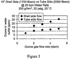
- FIG. 5 compares the shell side flows vs. tube side flow on ozone concentration for the contactor of Example 2.
- FIG. 6 compares the shell side flows vs. tube side flow on ozone concentration for the contactor of Example 1.
- FIG. 7 is an illustration of a prior art, tube side contactor.
- FIG. 8 is an illustration of an ozone test system.
- FIG. 9 compares the shell side flows vs. tube side flow on ozone concentration for the contactor of Example 3.
- FIG. 10 illustrates the efficiency of a shell side hollow fiber contactor of this invention.
- FIG. 11 illustrates the performance of a shell side hollow fiber contactor of this invention.
- FIG. 12 illustrates the relationship between ozonation and temperature.
- FIG. 13 illustrates the effect of water flow rate on ozonation.
- FIG. 14 illustrates the effect of water flow rate vs. pressure drop.
- FIG. 15 is a schematic of an ozonation recirculating loop.
- the asymmetric skinned hollow fiber membrane is produced by the process described in concurrent U.S. Provisional Patent Application Ser. No. 60/117,854 filed Jan. 29, 1999, the disclosure of which is incorporated by reference. That process is based on the Thermally Induced Phase Separation (TIPS) method of making porous structures and membranes.
- TIPS Thermally Induced Phase Separation
- the polymer comprises between approximately 12% to 75%, preferably 30% to 60%, by weight of the mixture.
- the polymers are perfluorinated thermoplastic polymers, more specifically poly(tetrafluoroethylene-co-perfluoro (alkylvinylether) such as PFA or MFA or tetrafluoroethylene-co-hexafluoropropylene) (FEP), or blends of these polymers, which are dissolved in a solvent to give a solution having an upper critical solution temperature, and which when the solution is cooled, separates into two phases by liquid-liquid phase separation.
- the solvent is chosen so the membrane formation occurs by liquid-liquid phase separation, rather than solid-liquid phase separation when the solution is extruded and cooled.
- Preferred solvents are saturated low molecular weight polymers of chloro-trifluoroethylene.
- a preferred solvent is HaloVac® 60 from Halocarbon Products Corporation, River Edge, N.J.
- the choice of the solvent is dictated by the ability of the solvent to dissolve the polymer when heated to form an upper critical solution temperature solution, but not to excessively boil at that temperature.
- Fiber extrusion is referred to as spinning and the extruded fiber length from the die exit to the take-up station is referred to as the spin line.
- the paste is metered into a heated extruder barrel where the temperature raised to above the upper critical solution temperature so that dissolution occurs.
- the homogeneous solution is then extruded through an annular die directly into a liquid cooling bath with no air gap.
- the lumen diameter is maintained with a constant pressure of gas.
- the liquid cooling bath is maintained at a temperature below the upper critical solution temperature of the polymer solution.
- the preferred bath liquid is not a solvent for the thermoplastic polymer, even at the extrusion temperature.
- a specially design die is used for horizontal spinning, where the spin line exists directly in the horizontal attitude, and is maintained more or less in that plane until at least the first guide roll.
- the die is firmly positioned against an insulated wall with the die tip penetrating through an opening having a liquid-tight seal in the insulator wall.
- a trough for cooling liquid flow is placed in a recess in the opposite side of the insulating wall, in a manner that will maintain the die nose outlet in a submerged condition. Cooling liquid flows in the trough and overflows in a region of the trough of lesser depth, keeping the die nose outlet submerged with a flow of cooling liquid.
- a booster heater and temperature control means is used to briefly raise the solution temperature at the die tip to prevent premature cooling.
- the dissolution solvent is removed by extraction and the resultant hollow fiber membrane is dried under restraint to prevent membrane shrinkage and collapse.
- the dried fiber may be heat set at 200° C. to 300° C.
- the fiber will be heat set or annealed under restraint at a temperature near the melting temperature of the fiber, which for the preferred polymer of this invention is within a range of from about 270° C. to about 290° C., preferably from about 275° C. to about 285° C., with the most preferred range from about 278° C. to about 282° C.
- a second, unrestrained, annealing step at similar temperatures is a preferred step. Annealing times for these steps is from about 6 to about 48 hours, more preferably, from about 18 to about 30 hours.
- the process described above is adapted so the lumen is filled with a liquid to prevent evaporation at the inner surface and the outer surface is exposed to the atmosphere in a very short air gap before entering the cooling bath.
- the lumen-filling liquid can be a liquid that does not boil or excessively vaporize during the extrusion process.
- Preferred liquids are mineral oil, silicone oil, and dioctylphthalate, with a most preferred liquid being a low molecular weight saturated chlorotrifluorohydrocarbon polymer.
- the process to produce these membranes is based on the Thermally Induced Phase Separation (TIPS) method of making porous structures and membranes.
- TIPS Thermally Induced Phase Separation
- a mixture of polymer pellets usually ground to a size smaller than supplied by the manufacturer, from about 100 to about 1000 microns, preferably about 300 microns, more preferably supplied or ground to a powder and an solvent, such as chlorotrifluoro-ethylene oligomer, is first mixed to a paste or paste-like consistency.
- the polymer comprises between approximately 12% to 35% by weight of the mixture.
- the solvent is chosen so the membrane formation occurs by liquid-liquid, rather than solid-liquid phase separation when the solution is extruded and cooled.
- Preferred solvents are saturated low molecular weight polymers of chlorotrifluoroethylene.
- a preferred solvent is HaloVac® 60 from Halocarbon Products Corporation, River Edge, N.J. Choice of the solvent is dictated by the ability of the solvent to dissolve the polymer when heated to
- Fiber extrusion is referred to as spinning and the extruded fiber length from the die exit to the take-up station is referred to as the spin line.
- the paste is metered into a heated extruder barrel where the temperature raised to above the upper critical solution temperature so that dissolution occurs.
- the homogeneous solution is then extruded through an annular die directly into a liquid cooling bath with no air gap.
- the liquid cooling bath is maintained at a temperature below the upper critical solution temperature of the polymer solution.
- the preferred bath liquid is not a solvent for the thermoplastic polymer, even at the extrusion temperature.
- the heated and shaped solution undergoes phase separation and a gel fiber results.
- the die tip is slightly submerged for vertical spinning, i.e., the spin line falls downward, in the direction of a freely falling body.
- a specially design die is used for horizontal spinning, where the spin line exits directly in the horizontal attitude, and is maintained more or less in that plane until at least the first guide roll.
- the die is firmly positioned against an insulated wall with the die tip penetrating through an opening having a liquid-tight seal in the insulator wall.
- a trough for cooling liquid flow is placed in a recess in the opposite side of the insulating wall, in a manner that will maintain the die nose outlet in a submerged condition. Cooling liquid flows in the trough and overflows in a region of the trough of lesser depth, keeping the die nose outlet submerged with a flow of cooling liquid.
- a booster heater and temperature control means is used to briefly raise the solution temperature at the die tip to prevent premature cooling.
- the dissolution solvent is removed by extraction and the resultant hollow fiber membrane is dried under restraint to prevent membrane shrinkage and collapse.
- the dried fiber may be heat set at 200° C. to 300° C.
- the method comprises vertically placing a portion of a bundle of hollow fiber membrane lengths with at least one closed, by the closed end, into a temporary recess made in a pool of molten thermoplastic polymer held in a container, holding the fiber lengths in a defined vertical position, maintaining the thermoplastic polymer in a molten state so that it flows into the temporary recess, around the fibers and vertically up the fibers, completely filling the interstitial spaces between fibers with the thermoplastic polymer.
- a temporary recess is a recess that remains as a recess in the molten potting material for a time sufficient to position and fix the fiber bundle in place and then will be filled by the molten thermoplastic.
- the temporary nature of the recess can be controlled by the temperature at which the potting material is held, the temperature at which the potting material is held during fiber bundle placement, and the physical properties of the potting material.
- a temporary recess can also be recess in a solid thermoplastic which will fill when the thermoplastic is heated to a temperature sufficiently above its softening or melting temperature to flow, and held at that temperature for the time necessary to fill the recess.
- the end of the fiber can be closed by sealing, plugging, or in a preferred embodiment, by being formed in a loop.
- the shell side contactor 10 of this invention includes a shell 12 formed of a copolymer of tetrafluoroethylene and perfluoroalkyl vinyl ether such as PFA or MFA or the like. Positioned within the shell is a plurality of hollow fibers 14 formed of a polymer composition described above. The fibers 14 are potted at each end of the shell 12 with a potting composition 16 as set forth above.
- a liquid enters shell 12 through inlet 18 and is removed from shell 12 through outlet 20 .
- Gas enters the lumens of hollow fiber 14 through gas inlets 22 utilizing a conventional manifold (not shown) and is removed from the lumens through gas outlets 24 .
- Gas such as ozone passes through the hollow fiber walls and is dissolved in the liquid such as water to form an aqueous ozone solution that can be utilized as an etchant.
- Ozone is produced by subjecting an oxygen containing gas such as 99% oxygen and 1% nitrogen to an electrical discharge in a manner well known in the art.
- Packing density relates to the amount of useful membrane surface per volume of the device. It is related to the number of fibers that can be potted in a finished contactor. During potting the fibers cannot be packaged too tightly in the hollow body or in a free-standing bundle, or they will prevent flow between fibers with the result of incomplete potting. If the packing density is correctly chosen for the specific fibers being potted, the flowing potting material will force the fibers apart. Packing density is defined as the ratio, expressed as a percentage, of the total cross-sectional area of all the fibers in the bundle to the inner area of the hollow body.
- the ratio is the area of the total cross-sectional area of all the fibers in the bundle to the cross-sectional area of the final potted fiber bundle.
- “Too tightly” is a function of packing density, final potted length, and fiber stiffness.
- a practitioner skilled in the art can determine the preferred packing density for a specific hollow fiber membrane.
- porous hollow fiber membranes made from poly(tetrafluoroethylene-co-perfluoro(alkylvinylether)) with an outer diameter of approximately 800-1000 microns and a wall thickness of approximately 200 microns, and about 10 centimeters long a packing density of at least less than 7000, and preferably at least less than 6500, gave satisfactory potted fibers.
- the shell side contactor 26 includes the potting composition 16 and hollow fibers 14 as well as parallel positioned spacer plates 28 that spread the hollow fiber 14 thereby to promote free flow of liquid within contactor 26 to reduce pressure drop within shell 12 .
- contactor 30 includes shell wall portion 30 which is thicker adjacent the liquid inlet 18 that the remainder of the shell wall 32 positioned remote from the inlet 18 . This configuration increases the volume of open space adjacent inlet 18 thereby to reduce pressure drop within the shell 12 .
- the contactor 36 includes an extended tube 38 which separates hollow fiber 14 .
- the tube 38 includes holes 40 through which liquid can pass into the shell 12 .
- the tube 38 promotes ingress of liquid into the shell 12 and to reduce pressure drop through the shell 12 .
- the present invention provides a shell side contactor which is highly efficient for forming relatively high concentration of ozonated water which contains at least about 0.34 ppm ozone per liter aqueous liquid per liter of interior housing volume (or 1.36 ppm for a radius volume calculation), preferably, at least 0.43 ppm ozone per liter aqueous liquid per liter of interior housing volume (or 1.72 ppm for a radius volume calculation).
- the efficiency produced by the present invention permits utilizing a desirably lower volume shell at relatively high flow rates of ozone and water through the shell side contactor of this invention.
- the efficiency of the present invention permits operating the shell side contactor on a one-pass basis of liquid through the contactor. This operation eliminates the need for a liquid flow path and accompanying pumping capacity to effect passage of the liquid through the contactor a plurality of times in order to produce an ozonated water product containing a desired minimum ozone concentration.
- the shell side contactor of this invention provides substantial advantages over prior art contactors which require a multiple pass liquid flow path.
- the shell (housing) side contactor of this invention has a high packing density of at least 0.34 m 2 membrane area/liter of interior shell volume, preferably at least 0.60 m 2 membrane area/liter of interior shell volume, so that the efficiencies set forth above are obtained.
- These high packing densities are obtained when utilizing hollow fibers having an exterior diameter of between about 300 microns and 1500 microns and preferably between about 600 microns and 1000 microns and an interior diameter between about 250 microns and 1100 microns.
- a packing density up to about 1.2 m 2 membrane area/liter of interior shell volume can be obtained with the contactor of this invention.
- the present invention provides a shell side contactor which is free of apparatus which effects turbulent liquid flow within the shell.
- the exclusion of such apparatus is advantageous since particle formation from turbulent flow activator apparatus is eliminated. The lack of such particles is essential when processing ozonated aqueous composition utilized in the electronics industry.
- such an apparatus provides a simple construction which reduces manufacturing costs.
- the apparatus of this invention contrasts, for example with the Liqui-CelTM contactor provided by Hoechest Celanese Corporation which utilizes hollow fibers positioned on a flexible substrate, such as a woven substrate which includes a turbulent liquid inducing baffle within the shell.
- the inlet gas pressure at the hollow fiber inlets typically is between about 1 and about 45 psig, preferably between about 10 and about 45 psig.
- Typical outlet gas pressure drop at the hollow fiber outlets is between about 0.1 and about 5 psig, preferably between about 0.1 and about 1 psig.
- Typical liquid pressure drop at the shell inlet typically is between about 5 and about 45 psig, preferably between about 2 and about 15 psig.
- the shell side contactor of this invention provides substantial advantages over a tube side-contactor.
- the mass transfer equation of tube-side flow is characterized by the following equation.
- shell-side transfer can be estimated by dividing the shell-side equation by the tube-side equation. It can be found that shell-side is between 5 times (5 ⁇ ) to 10 times (10 ⁇ ) better than tube-side.
- An additional benefit of shell-side transfer surface is the external membrane area. Since external membrane area is always larger than the internal area (tube-side transfer), shall-side transfer has the benefit of a larger contact area.
- shell-side mass transfer has many advantages, in general, design and construction of the device is more complicated. Usually it involves a center tube distribution for the liquid. The fibers may have to be woven onto a supporting mat. All these additional construction elements, which are absent in the tube-side configuration, pose significant challenges to the cartridge manufacturing process. In addition, supporting materials such as threads and mats are potential particle generators which may significantly contribute to microcontamination.
- the advantage of this invention is that the ability to obtain substantial benefits from shell-side mass transfer with relatively simple construction method. While this method doesn't provide the full benefit of shell-side mass transfer, the manufacturing cost for such a module is also less.
- a tube-side module is usually constructed with two large fittings at both ends for water to flow through the lumen of the hollow fibers.
- Two small gas fittings would be located on the shell near the exit and the entrance of the module.
- the fittings and the flow of the liquid and gas are reversed.
- two small fittings e.g., 1 ⁇ 4 inch
- the large fittings e.g., 1 ⁇ 2 inch to 1 inch, are needed for carrying water flow rate up to 10 gallons per minute (gpm).
- a shell-side module cannot be made just by reversing the flow and the fittings because the fiber bundle would produce enormous pressure drops (>30 psig@5 gpm).
- the packing density has to be reduced and the fiber bundle arrangement near the fittings has to be modified to minimize the pressure drop but at the same time avoiding massive channeling of water flow.
- pressure drop can be substantially reduced by decreasing the packing density from 58% to 48% and also offsetting the fiber bundle at the potted area.
- the mass transfer efficiency can be enhanced by jetting water into the fiber bundle and introducing gaps into the bundle.
- FIG. 7 shows a typical tube side flow pattern of the Prior Art hollow fiber contactor.
- the liquid flows inside the lumen of the fiber and the ozone gas flows (on the outer surface of the fiber) across shell side.
- the porous structure of hollow fibers without dense skin, allows only gas to diffuse through the membrane and dissolve in the water flowing in the lumen.
- the liquid and gas flows are switched for the shell side configuration—the liquid flows through the shell side and the ozone gas is routed through the fiber lumens.
- the contactor can be mounted either horizontally or vertically. As we describe below the two flow configurations offer widely different ozone transfer efficiency. Performance depends on the gas side flow rate, pressure, and concentration; and the liquid side flow rate, pressure, temperature, and pH.
- a contactor with dimensions of 2.25 inch inner diameter (ID) and 12 inches in length was made using porous skinless PFA hollow fibers.
- the fiber outer diameter (OD) was about 800 microns and the inner diameter (ID) about 500 microns.
- the number of the fibers was about 2100 and the packing density was around 0.46 m 2 of external membrane area per liter of internal cartridge volume.
- the fiber bundle was potted with an offset of 1 ⁇ 4 inch gas fitting at both end of the module. Two 1 inch fittings for water flow were bonded on the shell at cross-direction near the exit and entrance. The inside of the fitting was reduced to 1 ⁇ 2 inch using an insert to create jetting action of water into the bundle.
- the water fittings are located perpendicular to the offset of the potting such that a cavity is formed right under the fitting.
- the contactor was tested for ozonation efficiency. Ozone gas at 22 psig, 250 g/Nm 3 and 5 slpm was fed into the gas port of the contactor. Deionized water was pumped into the contactor using the shell-side water fitting at a rate of 5 gpm at 25° C. The water pressure drop across the module was about 5 psig. The concentration of ozone in the outlet water was measured using an IN-USA ozone sensor. After a couple of minutes, the ozone concentration in the water reached 23 ppm. Under the same operating conditions, the same contactor would produce less than 15 ppm using tube-side mode mass transfer. Therefore, the ozonation efficiency improvement was about 50%.
- the ozonation efficiency for this module was 0.4 ppm/lpm/liter of cartridge volume. This value comes from a volume calculation based on the diameter of the housing; when the volume calculation is based upon the radius of the housing, this efficiency value is 1.6 ppm.
- a comparison of the effect on ozone concentration over a shell side contactor of this invention and a tube side contactor is shown in FIG. 6 .
- a contactor with dimensions of 2 inches ID and 15 inches in length was made using porous skinless PFA hollow fibers.
- the fiber OD was about 800 micron and the ID about 500 micron.
- the number of the fibers was about 1700 and the packing density was around 0.42 m membrane per liter of internal cartridge volume.
- the contactor was fitted with 1 ⁇ 4 inch gas fitting at both end of the module. Two 1 ⁇ 2 inch fittings for water flow were bonded on the shell at cross direction near the exit and entrance.
- the contactor was tested for ozonation efficiency. Ozone gas at 22 psig, 250 g/Nm 3 and 5 slpm were fed into the gas port of the contactor. DI water was pumped into the contactor using the shell-side water fitting at a rate of 5 gpm at 25° C. The pressure drop was less than 5 psig. The concentration of ozone in the outlet water was measured using an IN-USA ozone sensor. After a couple of minutes, the ozone concentration in the water reached 26 ppm. Under the same operating conditions, the same contactor would produce less than 12 ppm using tube-side mode mass transfer. Therefore, the ozonation efficiency improvement was more than 100%.
- the ozonation efficiency of this module was 0.45 ppm/lpm/liter of internal cartridge volume. This value comes from a volume calculation based on the diameter of the housing; when the volume calculation is based upon the radius of the housing, this efficiency value is 1.8 ppm.
- a comparison of the effect on ozone concentration over a shell side contactor of this invention and a tube side contactor is shown in FIG. 5 .
- a contactor with dimensions of 2.25 inches ID and 12 inches in length was made using porous skinless PFA hollow fibers.
- the fiber outer diameter (OD) was about 700 microns and the inner diameter (ID) about 400 microns.
- the number of the fibers was about 4000 and the packing density was around 0.86 m 2 of external membrane area per liter of internal cartridge volume.
- the fiber bundle was potted with an offset of 1 ⁇ 4 inch gas fitting at both end of the module. Two 1 inch fittings for water flow were bonded on the shell at cross-direction near the exit and entrance. The inside of each fitting was reduced to 1 ⁇ 2 inch using an insert to create jetting action of water into the bundle.
- the water fittings are located perpendicular to the offset of the potting such that a cavity is formed right under the fitting.
- the contactor was tested for ozonation efficiency. Ozone gas at 22 psig, 250 g/Nm 3 and 5 slpm was fed into the gas port of the contactor. Deionized (DI) water was pumped into the contactor using the shell-side water fitting at a rate of 5 gpm at 25° C. The water pressure drop across the module was about 8 psig. The concentration of ozone in the outlet water was measured using an IN-USA ozone sensor. After a couple of minutes, the ozone concentration in the water reached at least 35 ppm. Under the same operating conditions, the same contactor would produce less than 16 ppm using tube-side mode mass transfer. Therefore, the ozonation efficiency improvement was about 100%.
- DI Deionized
- the ozonation efficiency for this module was 0.61 ppm/lpm/liter of cartridge volume. This value comes from a volume calculation based on the diameter of the housing; when the volume calculation is based upon the radius of the housing, this efficiency value is 2.44 ppm.
- FIG. 9 A comparison of the effect on ozone concentration over a shell side contactor of this invention and a tube side contactor is shown in FIG. 9 .
- the shell side module output increases from 25 ppm ozone at 3 slpm gas flow to 35 ppm at 7 slpm (at 20 liters per minute DI water flow rate, 250 g/Nm 3 gas concentration and 22 psi gas pressure).
- Such a high level of performance results from a high conversion efficiency (the amount of ozone transferred from gas side to water side) of over 60% at 3 slpm (see FIG. 10 ).
- the higher recovery is achieved as shell-side turbulence lowers the boundary layer impedance and results in higher mass transfer per unit membrane area. The high recovery helps lower the cost of ownership of the process tool.
- increasing the ozone gas side concentration increases the water ozone output.
- the effect of water side conditions on performance was investigated.
- the effect investigated in this example was the effect of flow rate and temperature.
- Equations 1 and 2 one can calculate the equilibrium solubility of ozone as a function of temperature for a given ozone generator condition.
- FIG. 12 shows the plot of equilibrium ozone solubility (ppm) in water as a function of temperature at ozone gas side pressure of 0.11 atm. This is the maximum concentration achievable at a given temperature. Decreasing the solution pH increases ozone solubility; however below pH 2, HCl lowers ozone solubility as Cl-ion reacts with ozone.
- the device output will approach the equilibrium value (predicted by FIG. 12 ) at very low water flow rates and decrease with an increase in water flow rate. This is because the contact time for ozone transfer into DI water is greater at low DI water flow rates.
- Plots in FIG. 13 show ozone output as a function of water flow rate for shell side and tube side contactors.
- the effect of a water side condition on performance investigated in this example was DI water flow rate versus pressure drop.
- the pressure drop versus water flow rate data are plotted in FIG. 14 .
- the shell side ozonator of the present invention should improve the cost of ownership for an ozone based wet cleans tool because of (1) its high productivity (ozone output per device volume), (2) smaller footprint, rapid start-up (faster mass transfer rate), and (3) ease of installation (only four tube connections). Because of its simple compact design and efficient performance, the module is appropriate for both a once-through (single pass) mode and in recirculation mode operations. It is easily adaptable in the cleaning processes using immersion baths, single wafer spin processors and in batch spray processors.
- the hollow fiber ozonator may produce ozone-DI water for various applications including room temperature wafer cleanings (5 ppm to 50 ppm ozone) and low temperature photoresist stripping (5° C., 100 ppm ozone).
- FIG. 15 shows schematics of an ozone-DI water recirculating loop.
- the present invention allows for improvements in the start up time to reach the desired ozone concentration in cleaning tools and maintain the stability of the ozone concentration in a recirculating control loop over time for a bubble free DI water-Ozone application.
- the smaller size/footprint, shorter time to reach the desired ozone concentration, and the ease of controlling the device of the present invention in a narrow range of the ozone concentration allows the user better process control.
- An added advantage is the ability of the module to withstand high water pressure of about 2-2.5 bar, with intermittent pressure spikes of 3-4 bars.
Landscapes
- Chemical & Material Sciences (AREA)
- Chemical Kinetics & Catalysis (AREA)
- Engineering & Computer Science (AREA)
- Manufacturing & Machinery (AREA)
- Organic Chemistry (AREA)
- Analytical Chemistry (AREA)
- Inorganic Chemistry (AREA)
- Oil, Petroleum & Natural Gas (AREA)
- Dispersion Chemistry (AREA)
- General Chemical & Material Sciences (AREA)
- Water Supply & Treatment (AREA)
- Thermal Sciences (AREA)
- Physics & Mathematics (AREA)
- Combustion & Propulsion (AREA)
- Separation Using Semi-Permeable Membranes (AREA)
Abstract
Description
Sh=K*d/D ab=1.64*R 0.33 Sc 0.33*(D/L)0.33
where:
Sh=Sherwood Number,
K=mass transfer coefficient, cm/s,
L=length of fiber, cm
d=ID of fiber, cm.
Dab=diffusion coefficient of ozone, cm2/sec
Re=Reynold's Number, pvd/μ
Sc=Schmidt's Number, μ/ρDab
v=velocity, cm/sec
ρ=density, grams/cm3
Sh=K*d/D ab=0.36*Re 0.55 Sc 0.33
Henry's Law: P=HX (Equation 1)
H=3.8×10⁷[OH—]0.035exp(2428/T) (Equation 2)
Claims (19)
Priority Applications (1)
| Application Number | Priority Date | Filing Date | Title |
|---|---|---|---|
| US12/050,247 US7717405B2 (en) | 2002-03-19 | 2008-03-18 | Hollow fiber membrane contact apparatus and process |
Applications Claiming Priority (5)
| Application Number | Priority Date | Filing Date | Title |
|---|---|---|---|
| US36685702P | 2002-03-19 | 2002-03-19 | |
| US39746202P | 2002-07-19 | 2002-07-19 | |
| US10/508,059 US20050230856A1 (en) | 2002-03-19 | 2003-03-06 | Hollow fiber membrane contact apparatus and process |
| PCT/US2003/006928 WO2003080228A1 (en) | 2002-03-19 | 2003-03-06 | Hollow fiber membrane contact apparatus and process |
| US12/050,247 US7717405B2 (en) | 2002-03-19 | 2008-03-18 | Hollow fiber membrane contact apparatus and process |
Related Parent Applications (3)
| Application Number | Title | Priority Date | Filing Date |
|---|---|---|---|
| PCT/US2003/006928 Continuation WO2003080228A1 (en) | 2002-03-19 | 2003-03-06 | Hollow fiber membrane contact apparatus and process |
| US10/508,059 Continuation US20050230856A1 (en) | 2002-03-19 | 2003-03-06 | Hollow fiber membrane contact apparatus and process |
| US10508059 Continuation | 2003-03-06 |
Publications (2)
| Publication Number | Publication Date |
|---|---|
| US20080156191A1 US20080156191A1 (en) | 2008-07-03 |
| US7717405B2 true US7717405B2 (en) | 2010-05-18 |
Family
ID=28457143
Family Applications (2)
| Application Number | Title | Priority Date | Filing Date |
|---|---|---|---|
| US10/508,059 Abandoned US20050230856A1 (en) | 2002-03-19 | 2003-03-06 | Hollow fiber membrane contact apparatus and process |
| US12/050,247 Expired - Fee Related US7717405B2 (en) | 2002-03-19 | 2008-03-18 | Hollow fiber membrane contact apparatus and process |
Family Applications Before (1)
| Application Number | Title | Priority Date | Filing Date |
|---|---|---|---|
| US10/508,059 Abandoned US20050230856A1 (en) | 2002-03-19 | 2003-03-06 | Hollow fiber membrane contact apparatus and process |
Country Status (8)
| Country | Link |
|---|---|
| US (2) | US20050230856A1 (en) |
| EP (1) | EP1485193B1 (en) |
| JP (1) | JP4498748B2 (en) |
| KR (1) | KR101049989B1 (en) |
| CN (1) | CN1642628B (en) |
| DE (1) | DE60316264T2 (en) |
| TW (1) | TW590790B (en) |
| WO (1) | WO2003080228A1 (en) |
Cited By (2)
| Publication number | Priority date | Publication date | Assignee | Title |
|---|---|---|---|---|
| US9291083B2 (en) * | 2013-06-14 | 2016-03-22 | Ionada Incorporated | Membrane-based exhaust gas scrubbing method and system |
| US10654006B1 (en) | 2017-07-11 | 2020-05-19 | Biotherm Hydronic, Inc. | Devices and methods for infusing gas into a liquid |
Families Citing this family (82)
| Publication number | Priority date | Publication date | Assignee | Title |
|---|---|---|---|---|
| US7708013B2 (en) * | 2000-12-08 | 2010-05-04 | Vapotherm, Inc. | Apparatus and method for delivering water vapor to a gas |
| WO2004039482A2 (en) * | 2002-10-31 | 2004-05-13 | Glassford Craig L | Controlled atmosphere gas infusion |
| US8828226B2 (en) | 2003-03-01 | 2014-09-09 | The Trustees Of Boston University | System for assessing the efficacy of stored red blood cells using microvascular networks |
| AU2003903507A0 (en) | 2003-07-08 | 2003-07-24 | U. S. Filter Wastewater Group, Inc. | Membrane post-treatment |
| US7819956B2 (en) * | 2004-07-02 | 2010-10-26 | Siemens Water Technologies Corp. | Gas transfer membrane |
| AU2005259830C1 (en) * | 2004-07-02 | 2011-07-21 | Evoqua Water Technologies Llc | Gas transfer membrane |
| US7379487B2 (en) | 2005-02-14 | 2008-05-27 | Neumann Information Systems, Inc. | Two phase reactor |
| US8864876B2 (en) | 2005-02-14 | 2014-10-21 | Neumann Systems Group, Inc. | Indirect and direct method of sequestering contaminates |
| US8398059B2 (en) | 2005-02-14 | 2013-03-19 | Neumann Systems Group, Inc. | Gas liquid contactor and method thereof |
| US7393388B2 (en) | 2005-05-13 | 2008-07-01 | United Technologies Corporation | Spiral wound fuel stabilization unit for fuel de-oxygenation |
| US7435283B2 (en) | 2005-05-18 | 2008-10-14 | United Technologies Corporation | Modular fuel stabilization system |
| US7465336B2 (en) | 2005-06-09 | 2008-12-16 | United Technologies Corporation | Fuel deoxygenation system with non-planar plate members |
| US7377112B2 (en) | 2005-06-22 | 2008-05-27 | United Technologies Corporation | Fuel deoxygenation for improved combustion performance |
| US7615104B2 (en) | 2005-11-03 | 2009-11-10 | United Technologies Corporation | Fuel deoxygenation system with multi-layer oxygen permeable membrane |
| US7824470B2 (en) | 2006-01-18 | 2010-11-02 | United Technologies Corporation | Method for enhancing mass transport in fuel deoxygenation systems |
| US7569099B2 (en) | 2006-01-18 | 2009-08-04 | United Technologies Corporation | Fuel deoxygenation system with non-metallic fuel plate assembly |
| US7582137B2 (en) | 2006-01-18 | 2009-09-01 | United Technologies Corporation | Fuel deoxygenator with non-planar fuel channel and oxygen permeable membrane |
| KR20100080552A (en) * | 2007-10-16 | 2010-07-08 | 캐리어 코포레이션 | Non-vacuum absorption refrigeration |
| US20110030730A1 (en) * | 2008-03-13 | 2011-02-10 | Lynn Daniel W | System for producing and distributing an ozonated fluid |
| KR20110008319A (en) * | 2008-05-19 | 2011-01-26 | 엔테그리스, 아이엔씨. | Vaporization System and Method for Making Inorganic Foam Solution of Gas in Liquid |
| US20100024651A1 (en) * | 2008-07-30 | 2010-02-04 | General Electric Company | Membrane contactor systems for gas-liquid contact |
| US8066027B2 (en) * | 2008-07-30 | 2011-11-29 | Sprague Alden C | Vacuum activated closed loop system |
| NZ592100A (en) * | 2008-09-26 | 2013-11-29 | Neumann Systems Group Inc | Gas liquid contactor and effluent cleaning system and method |
| KR100934587B1 (en) * | 2009-06-04 | 2009-12-31 | 주식회사 그린기술산업 | Diffuser and manufacturing method |
| CN101564638B (en) * | 2009-06-05 | 2011-04-20 | 北京化工大学 | Method for strengthening mass transfer process of membrane absorption by utilizing solid phase particles |
| US8544492B2 (en) * | 2009-07-25 | 2013-10-01 | Alden C. Sprague | Vacuum activated power tower |
| US8506685B2 (en) * | 2009-08-17 | 2013-08-13 | Celgard Llc | High pressure liquid degassing membrane contactors and methods of manufacturing and use |
| US12089589B2 (en) | 2009-10-12 | 2024-09-17 | Hemanext Inc. | Irradiation of red blood cells and anaerobic storage |
| CA2781866C (en) | 2009-10-12 | 2019-12-03 | New Health Sciences, Inc. | Blood storage bag system and depletion devices with oxygen and carbon dioxide depletion capabilities |
| US11284616B2 (en) | 2010-05-05 | 2022-03-29 | Hemanext Inc. | Irradiation of red blood cells and anaerobic storage |
| US9199016B2 (en) | 2009-10-12 | 2015-12-01 | New Health Sciences, Inc. | System for extended storage of red blood cells and methods of use |
| CN102905522A (en) | 2009-10-12 | 2013-01-30 | 新健康科学股份有限公司 | Oxygen depletion devices and methods for removing oxygen from red blood cells |
| US8617396B2 (en) * | 2010-01-15 | 2013-12-31 | Board Of Regents, The University Of Texas System | Non-dispersive process for insoluble oil recovery from aqueous slurries |
| MX350472B (en) * | 2010-01-15 | 2017-09-07 | Univ Texas | NON-DISPERSIVE PROCESS FOR THE RECOVERY OF INSOLUBLE OIL FROM WATERPROOF SUSPENSIONS. |
| US9149772B2 (en) | 2010-01-15 | 2015-10-06 | Board Of Regents, The University Of Texas Systems | Enhancing flux of a microporous hollow fiber membrane |
| US8491792B2 (en) * | 2010-01-15 | 2013-07-23 | Board Of Regents, The University Of Texas System | Non-dispersive process for insoluble oil recovery from aqueous slurries |
| US9643127B2 (en) | 2010-01-15 | 2017-05-09 | Board Of Regents Of The University Of Texas System | Simultaneous removal of oil and gases from liquid sources using a hollow fiber membrane |
| US9688921B2 (en) | 2013-02-26 | 2017-06-27 | Board Of Regents, The University Of Texas System | Oil quality using a microporous hollow fiber membrane |
| US9782726B2 (en) | 2010-01-15 | 2017-10-10 | Board Of Regents, The University Of Texas System | Non-dispersive process for oil recovery |
| US20120024784A1 (en) * | 2010-07-30 | 2012-02-02 | Christopher Clark | Fluid Gasification/Degasification Apparatuses, Systems, and Processes |
| CN101884878B (en) * | 2010-08-18 | 2012-09-26 | 天津工业大学 | Hollow fiber porous membrane in perfluoro polymer and preparation method thereof |
| US9339025B2 (en) | 2010-08-25 | 2016-05-17 | New Health Sciences, Inc. | Method for enhancing red blood cell quality and survival during storage |
| PT2635114T (en) | 2010-11-05 | 2020-06-16 | New Health Sciences Inc | Irradiation of red blood cells and anaerobic storage |
| CN102485320B (en) * | 2010-12-05 | 2013-09-18 | 国家海洋局天津海水淡化与综合利用研究所 | Device for desulfurizing flue gas by seawater through membrane absorption and its process |
| US8540081B2 (en) | 2011-03-16 | 2013-09-24 | Markel Corporation | Fluoropolymer hollow fiber membrane with fluoro-copolymer and fluoro-terpolymer bonded end portion(s) and method to fabricate |
| US9067004B2 (en) | 2011-03-28 | 2015-06-30 | New Health Sciences, Inc. | Method and system for removing oxygen and carbon dioxide during red cell blood processing using an inert carrier gas and manifold assembly |
| ES2984863T3 (en) | 2011-08-10 | 2024-10-31 | Hemanext Inc | Integrated leukocyte filtration, oxygen and/or CO2 depletion, and plasma separation device |
| KR101322709B1 (en) * | 2011-12-08 | 2013-10-28 | (주)세프라텍 | Membrane contact method for seperating carbon dioxide and system therefor |
| CN102513040B (en) * | 2011-12-29 | 2014-04-23 | 江苏久吾高科技股份有限公司 | Ceramic Membrane Microporous Gas Distributor |
| CN102580573B (en) * | 2012-03-01 | 2013-12-25 | 天津工业大学 | Method for producing perfluor polymer hollow fiber membrane |
| WO2013188849A1 (en) | 2012-06-14 | 2013-12-19 | Board Of Regents, The University Of Texas System | Non-dispersive oil recovery from oil industry liquid sources |
| KR20150054918A (en) | 2012-09-14 | 2015-05-20 | 에보쿠아 워터 테크놀로지스 엘엘씨 | A polymer blend for membranes |
| ES2900298T3 (en) | 2013-02-28 | 2022-03-16 | Hemanext Inc | Gas depletion device for blood products |
| JP6161124B2 (en) * | 2013-03-29 | 2017-07-12 | 富士フイルム株式会社 | Method for producing acid gas separation composite membrane and acid gas separation membrane module |
| FR3011484B1 (en) * | 2013-10-09 | 2017-06-23 | Air Liquide | AIR SEPARATION DEVICE, INERTING DEVICE AND AIRCRAFT COMPRISING SUCH A DEVICE |
| CA2891161A1 (en) * | 2014-05-28 | 2015-11-28 | Chemetics Inc. | Membrane separation at high temperature differential |
| CA2967186A1 (en) * | 2014-11-13 | 2016-05-19 | Wade Campbell | Gas/liquid mixing apparatus |
| DE102014118130A1 (en) | 2014-12-08 | 2016-06-09 | Technische Universität Berlin | Fluid distribution device for a gas-liquid contactor, gas-liquid contactor and method for displacing a liquid with a gas |
| ES2961836T3 (en) * | 2014-12-24 | 2024-03-14 | Dainippon Ink & Chemicals | Degassing procedure in a hollow fiber degassing module |
| PT3970731T (en) | 2015-03-10 | 2026-02-24 | Hemanext Inc | Disposable oxygen reduction kits, devices and methods of use thereof. |
| CN104707494A (en) * | 2015-03-30 | 2015-06-17 | 上海纳诺巴伯纳米科技有限公司 | Preparation device and preparation method for over-saturated hydrogen solution |
| WO2016168644A1 (en) * | 2015-04-17 | 2016-10-20 | Georgia Tech Research Corporation | Hollow fiber membranes for solubilizing a gas into a liquid, devices for same, and processes of same |
| WO2016172645A1 (en) | 2015-04-23 | 2016-10-27 | New Health Sciences, Inc. | Anaerobic blood storage containers |
| CA2985799A1 (en) | 2015-05-18 | 2016-11-24 | New Health Sciences, Inc. | Methods for the storage of whole blood, and compositions thereof |
| WO2017011068A1 (en) | 2015-07-14 | 2017-01-19 | Evoqua Water Technologies Llc | Aeration device for filtration system |
| EP3202721A1 (en) * | 2016-02-02 | 2017-08-09 | Eawag | Ozone-based advanced oxidation process |
| KR20240132129A (en) | 2016-05-27 | 2024-09-02 | 헤마넥스트 인코포레이티드 | Anaerobic blood storage and pathogen inactivation method |
| US10527011B2 (en) * | 2017-06-06 | 2020-01-07 | Hamilton Sundstrand Corporation | Sonication-assisted fuel deoxygenation |
| KR20190062168A (en) * | 2017-11-28 | 2019-06-05 | 주식회사 엘지화학 | Method for preparing porous fluorine resin film |
| JP7016331B2 (en) * | 2018-05-28 | 2022-02-04 | 野村マイクロ・サイエンス株式会社 | Ultrapure water production method using an ultrafiltration membrane module and an ultrafiltration membrane module |
| CN109445254A (en) * | 2018-11-16 | 2019-03-08 | 福建省福联集成电路有限公司 | A kind of device reducing development pipeline bubble |
| EP3721970A1 (en) * | 2019-04-08 | 2020-10-14 | Linde GmbH | Membrane separation unit, assembly of membrane separation units and membrane separation method |
| KR102250106B1 (en) | 2019-12-09 | 2021-05-11 | 고등기술연구원연구조합 | Exhaust gas cleaning apparatus using membrane connector |
| US11459952B2 (en) * | 2019-12-18 | 2022-10-04 | Raytheon Technologies Corporation | Air/oil mixture separation systems for gas turbine engines |
| RU2750524C1 (en) * | 2020-02-14 | 2021-06-29 | Общество с ограниченной ответственностью "Салютарис" | Membrane hollow fiber blood oxygenator |
| CN112093303B (en) * | 2020-08-19 | 2022-07-19 | 江苏全卓软件科技有限公司 | Membrane type water sealer and storage tank waste gas collecting system and method using same |
| CN114247396B (en) * | 2020-09-23 | 2022-11-08 | 中国科学院大连化学物理研究所 | Polytetrafluoroethylene hollow fiber membrane microchannel reactor and preparation and application thereof |
| KR102448521B1 (en) | 2020-11-26 | 2022-09-28 | 고등기술연구원연구조합 | Hollow fiber module of membrane contactor and manufacturing method thereof |
| IL308177A (en) * | 2021-05-06 | 2023-12-01 | Prosper Tech Llc | Systems and methods of gas infusion for wastewater treatment |
| CN117899681A (en) * | 2023-12-28 | 2024-04-19 | 宁波水艺膜科技发展有限公司 | Efficient preparation method of high-concentration ozone water |
| WO2025255038A1 (en) * | 2024-06-04 | 2025-12-11 | Prosper Technologies, Llc | System and methods of gas infusion module for infusing o3 as a water treatment process or disinfection process and gas infusion control valve for insitu oxygen curtain device |
| WO2026009800A1 (en) * | 2024-07-05 | 2026-01-08 | 住友電工ファインポリマー株式会社 | Corrosive gas supply device |
Citations (25)
| Publication number | Priority date | Publication date | Assignee | Title |
|---|---|---|---|---|
| US3708071A (en) | 1970-08-05 | 1973-01-02 | Abcor Inc | Hollow fiber membrane device and method of fabricating same |
| JPS5895202U (en) | 1981-12-22 | 1983-06-28 | 株式会社クラレ | fluid separation device |
| JPS62144707A (en) | 1985-12-18 | 1987-06-27 | Nippon Atom Ind Group Co Ltd | Hollow yarn membrane filter |
| US5266639A (en) | 1992-08-28 | 1993-11-30 | E. I. Du Pont De Nemours And Company | Low-melting tetrafluorethylene copolymer and its uses |
| US5328610A (en) | 1993-06-15 | 1994-07-12 | Integrated Process Technologies | Self-supported low pressure drop hollow fiber membrane panel and contactor module |
| JPH06319961A (en) | 1993-05-13 | 1994-11-22 | Asahi Chem Ind Co Ltd | Membrane module |
| US5463006A (en) | 1993-07-05 | 1995-10-31 | Ausimont, S.P.A. | Thermoprocessable copolymers of tetrafluoroethylene |
| US5464480A (en) | 1993-07-16 | 1995-11-07 | Legacy Systems, Inc. | Process and apparatus for the treatment of semiconductor wafers in a fluid |
| US5670094A (en) | 1995-01-30 | 1997-09-23 | Ebara Corporation | Method of and apparatus for producing ozonized water |
| US5749941A (en) | 1994-03-25 | 1998-05-12 | Nederlandse Organisatie Voor Toegepast-Natuurwetenschappelijk Onderzoek Tno | Method for gas absorption across a membrane |
| CN1191767A (en) | 1996-12-18 | 1998-09-02 | 气体产品与化学公司 | Hollow fiber fluid separator with transverse flow channels |
| JPH10305218A (en) | 1997-05-07 | 1998-11-17 | Nikkiso Co Ltd | Hollow fiber type module and manufacturing method thereof |
| US5902747A (en) | 1996-10-24 | 1999-05-11 | Compact Membrane Systems, Inc. | Method of gasifying or degasifying a liquid containing cells |
| WO2000004484A2 (en) | 1998-07-17 | 2000-01-27 | Intergraph Corporation | Wide instruction word graphics processor |
| WO2000044482A2 (en) | 1999-01-29 | 2000-08-03 | Millipore Corporation | Skinned hollow fiber membrane and method of manufacture |
| WO2000044479A1 (en) | 1999-01-29 | 2000-08-03 | Millipore Corporation | Hollow fiber membrane contactor |
| WO2000044480A1 (en) | 1999-01-29 | 2000-08-03 | Mykrolis Corporation | Method for manufacturing hollow fiber membranes |
| US6113782A (en) | 1998-07-28 | 2000-09-05 | Terumo Cardiovascular Systems Corporation | Potting of tubular bundles in housing |
| JP2000246064A (en) | 1999-02-26 | 2000-09-12 | Sumitomo Electric Ind Ltd | Gas dissolution module |
| WO2001039869A1 (en) | 1999-12-03 | 2001-06-07 | Degremont Sa | Method for membrane filtration of liquids and device therefor |
| US6582496B1 (en) | 2000-01-28 | 2003-06-24 | Mykrolis Corporation | Hollow fiber membrane contactor |
| US6802973B2 (en) | 1999-01-29 | 2004-10-12 | Mykrolis Corporation | Microporous hollow fiber membranes from perfluorinated thermoplastic polymers |
| US20040251010A1 (en) | 2001-10-01 | 2004-12-16 | Doh Cha P | Exchange apparatus |
| US6921482B1 (en) | 1999-01-29 | 2005-07-26 | Mykrolis Corporation | Skinned hollow fiber membrane and method of manufacture |
| US20070089489A1 (en) * | 2005-10-11 | 2007-04-26 | Millipore Corporation | Methods and systems for integrity testing of porous materials |
Family Cites Families (4)
| Publication number | Priority date | Publication date | Assignee | Title |
|---|---|---|---|---|
| US2000400A (en) * | 1931-11-11 | 1935-05-07 | James G Maclaren | Pneumatic dispatch carrier |
| JPH0639256A (en) * | 1991-04-03 | 1994-02-15 | Permelec Electrode Ltd | Method and apparatus for dissolving ozone |
| JPH06327905A (en) * | 1993-05-21 | 1994-11-29 | Toray Ind Inc | Degassing membrane module and operating method thereof |
| AU2975600A (en) * | 1999-01-29 | 2000-08-18 | Millipore Corporation | Microporous hollow fiber membranes from perfluorinated thermoplastic polymers |
-
2003
- 2003-03-06 WO PCT/US2003/006928 patent/WO2003080228A1/en not_active Ceased
- 2003-03-06 CN CN038065606A patent/CN1642628B/en not_active Expired - Fee Related
- 2003-03-06 US US10/508,059 patent/US20050230856A1/en not_active Abandoned
- 2003-03-06 EP EP03711448A patent/EP1485193B1/en not_active Expired - Lifetime
- 2003-03-06 KR KR1020047014623A patent/KR101049989B1/en not_active Expired - Fee Related
- 2003-03-06 DE DE60316264T patent/DE60316264T2/en not_active Expired - Lifetime
- 2003-03-06 JP JP2003578047A patent/JP4498748B2/en not_active Expired - Fee Related
- 2003-03-14 TW TW092105646A patent/TW590790B/en not_active IP Right Cessation
-
2008
- 2008-03-18 US US12/050,247 patent/US7717405B2/en not_active Expired - Fee Related
Patent Citations (30)
| Publication number | Priority date | Publication date | Assignee | Title |
|---|---|---|---|---|
| US3708071A (en) | 1970-08-05 | 1973-01-02 | Abcor Inc | Hollow fiber membrane device and method of fabricating same |
| JPS5895202U (en) | 1981-12-22 | 1983-06-28 | 株式会社クラレ | fluid separation device |
| JPS62144707A (en) | 1985-12-18 | 1987-06-27 | Nippon Atom Ind Group Co Ltd | Hollow yarn membrane filter |
| US5266639A (en) | 1992-08-28 | 1993-11-30 | E. I. Du Pont De Nemours And Company | Low-melting tetrafluorethylene copolymer and its uses |
| JPH06319961A (en) | 1993-05-13 | 1994-11-22 | Asahi Chem Ind Co Ltd | Membrane module |
| US5328610A (en) | 1993-06-15 | 1994-07-12 | Integrated Process Technologies | Self-supported low pressure drop hollow fiber membrane panel and contactor module |
| US5463006A (en) | 1993-07-05 | 1995-10-31 | Ausimont, S.P.A. | Thermoprocessable copolymers of tetrafluoroethylene |
| US5464480A (en) | 1993-07-16 | 1995-11-07 | Legacy Systems, Inc. | Process and apparatus for the treatment of semiconductor wafers in a fluid |
| US5749941A (en) | 1994-03-25 | 1998-05-12 | Nederlandse Organisatie Voor Toegepast-Natuurwetenschappelijk Onderzoek Tno | Method for gas absorption across a membrane |
| US5670094A (en) | 1995-01-30 | 1997-09-23 | Ebara Corporation | Method of and apparatus for producing ozonized water |
| US5902747A (en) | 1996-10-24 | 1999-05-11 | Compact Membrane Systems, Inc. | Method of gasifying or degasifying a liquid containing cells |
| CN1191767A (en) | 1996-12-18 | 1998-09-02 | 气体产品与化学公司 | Hollow fiber fluid separator with transverse flow channels |
| JPH10305218A (en) | 1997-05-07 | 1998-11-17 | Nikkiso Co Ltd | Hollow fiber type module and manufacturing method thereof |
| WO2000004484A2 (en) | 1998-07-17 | 2000-01-27 | Intergraph Corporation | Wide instruction word graphics processor |
| US6113782A (en) | 1998-07-28 | 2000-09-05 | Terumo Cardiovascular Systems Corporation | Potting of tubular bundles in housing |
| WO2000044482A2 (en) | 1999-01-29 | 2000-08-03 | Millipore Corporation | Skinned hollow fiber membrane and method of manufacture |
| US6805731B2 (en) | 1999-01-29 | 2004-10-19 | Mykrolis Corporation | Hollow fiber membrane contactor |
| WO2000044479A1 (en) | 1999-01-29 | 2000-08-03 | Millipore Corporation | Hollow fiber membrane contactor |
| US6977043B2 (en) | 1999-01-29 | 2005-12-20 | Mykrolis Corporation | Skinned hollow fiber membrane and method of manufacture |
| US6921482B1 (en) | 1999-01-29 | 2005-07-26 | Mykrolis Corporation | Skinned hollow fiber membrane and method of manufacture |
| WO2000044480A1 (en) | 1999-01-29 | 2000-08-03 | Mykrolis Corporation | Method for manufacturing hollow fiber membranes |
| US6663745B1 (en) | 1999-01-29 | 2003-12-16 | Mykrolis Corporation | Method for manufacturing hollow fiber membranes |
| US20040094466A1 (en) | 1999-01-29 | 2004-05-20 | Kwok-Shun Cheng | Method for manufacturing hollow fiber membranes |
| US6802973B2 (en) | 1999-01-29 | 2004-10-12 | Mykrolis Corporation | Microporous hollow fiber membranes from perfluorinated thermoplastic polymers |
| US6802972B1 (en) | 1999-01-29 | 2004-10-12 | Mykrolis Corporation | Microporous hollow fiber membranes from perfluorinated thermoplastic polymers |
| JP2000246064A (en) | 1999-02-26 | 2000-09-12 | Sumitomo Electric Ind Ltd | Gas dissolution module |
| WO2001039869A1 (en) | 1999-12-03 | 2001-06-07 | Degremont Sa | Method for membrane filtration of liquids and device therefor |
| US6582496B1 (en) | 2000-01-28 | 2003-06-24 | Mykrolis Corporation | Hollow fiber membrane contactor |
| US20040251010A1 (en) | 2001-10-01 | 2004-12-16 | Doh Cha P | Exchange apparatus |
| US20070089489A1 (en) * | 2005-10-11 | 2007-04-26 | Millipore Corporation | Methods and systems for integrity testing of porous materials |
Non-Patent Citations (2)
| Title |
|---|
| Ohmi, et al., J. Electrochem. Soc., Mar. 1993, vol. 140 (3). 804-810. |
| Roth, et al., Ind. Eng. Chem. Fundam., 1981, 20, 137-140. |
Cited By (3)
| Publication number | Priority date | Publication date | Assignee | Title |
|---|---|---|---|---|
| US9291083B2 (en) * | 2013-06-14 | 2016-03-22 | Ionada Incorporated | Membrane-based exhaust gas scrubbing method and system |
| US10654006B1 (en) | 2017-07-11 | 2020-05-19 | Biotherm Hydronic, Inc. | Devices and methods for infusing gas into a liquid |
| US10933386B1 (en) | 2017-07-11 | 2021-03-02 | Biotherm Hydronic, Inc. | Devices and methods for infusing gas into a liquid |
Also Published As
| Publication number | Publication date |
|---|---|
| TW200305454A (en) | 2003-11-01 |
| US20050230856A1 (en) | 2005-10-20 |
| KR20040101318A (en) | 2004-12-02 |
| CN1642628B (en) | 2010-06-16 |
| KR101049989B1 (en) | 2011-07-19 |
| DE60316264T2 (en) | 2008-05-29 |
| CN1642628A (en) | 2005-07-20 |
| DE60316264D1 (en) | 2007-10-25 |
| US20080156191A1 (en) | 2008-07-03 |
| JP4498748B2 (en) | 2010-07-07 |
| EP1485193A4 (en) | 2005-11-16 |
| EP1485193A1 (en) | 2004-12-15 |
| TW590790B (en) | 2004-06-11 |
| WO2003080228A1 (en) | 2003-10-02 |
| JP2005520679A (en) | 2005-07-14 |
| EP1485193B1 (en) | 2007-09-12 |
Similar Documents
| Publication | Publication Date | Title |
|---|---|---|
| US7717405B2 (en) | Hollow fiber membrane contact apparatus and process | |
| US6582496B1 (en) | Hollow fiber membrane contactor | |
| EP1148931B1 (en) | Hollow fiber membrane contactor | |
| KR101257959B1 (en) | Exchange devices with potted hollow conduits | |
| KR20190117707A (en) | Operation method of porous membrane for membrane distillation and module for membrane distillation | |
| US6921482B1 (en) | Skinned hollow fiber membrane and method of manufacture | |
| JP2002535131A (en) | Skinned hollow fiber membrane and method for producing the same | |
| US20030201223A1 (en) | Microporous hollow fiber membranes from perfluorinated thermoplastic polymers | |
| EP1144097B1 (en) | Process for the production of microporous hollow fiber membranes from perfluorinated thermoplastic polymers | |
| JPH10202074A (en) | Asymmetric structure fluororesin tube, method for producing this tube, and degassing method and degassing device using this tube | |
| WO2022239333A1 (en) | Air-supply module | |
| CN118401297A (en) | Hollow fiber membrane module and hollow fiber membrane for module |
Legal Events
| Date | Code | Title | Description |
|---|---|---|---|
| AS | Assignment |
Owner name: WELLS FARGO BANK, NATIONAL ASSOCIATION, AS AGENT, Free format text: SECURITY AGREEMENT;ASSIGNOR:ENTEGRIS, INC.;REEL/FRAME:022354/0784 Effective date: 20090302 Owner name: WELLS FARGO BANK, NATIONAL ASSOCIATION, AS AGENT,M Free format text: SECURITY AGREEMENT;ASSIGNOR:ENTEGRIS, INC.;REEL/FRAME:022354/0784 Effective date: 20090302 |
|
| STCF | Information on status: patent grant |
Free format text: PATENTED CASE |
|
| AS | Assignment |
Owner name: ENTEGRIS, INC., MASSACHUSETTS Free format text: RELEASE BY SECURED PARTY;ASSIGNOR:WELLS FARGO BANK NATIONAL ASSOCIATION;REEL/FRAME:026764/0880 Effective date: 20110609 |
|
| FPAY | Fee payment |
Year of fee payment: 4 |
|
| AS | Assignment |
Owner name: GOLDMAN SACHS BANK USA, AS COLLATERAL AGENT, NEW Y Free format text: SECURITY INTEREST;ASSIGNORS:ENTEGRIS, INC.;POCO GRAPHITE, INC.;ATMI, INC.;AND OTHERS;REEL/FRAME:032815/0852 Effective date: 20140430 Owner name: GOLDMAN SACHS BANK USA, AS COLLATERAL AGENT, NEW YORK Free format text: SECURITY INTEREST;ASSIGNORS:ENTEGRIS, INC.;POCO GRAPHITE, INC.;ATMI, INC.;AND OTHERS;REEL/FRAME:032815/0852 Effective date: 20140430 |
|
| AS | Assignment |
Owner name: GOLDMAN SACHS BANK USA, AS COLLATERAL AGENT, NEW YORK Free format text: SECURITY INTEREST;ASSIGNORS:ENTEGRIS, INC.;POCO GRAPHITE, INC.;ATMI, INC.;AND OTHERS;REEL/FRAME:032812/0192 Effective date: 20140430 Owner name: GOLDMAN SACHS BANK USA, AS COLLATERAL AGENT, NEW Y Free format text: SECURITY INTEREST;ASSIGNORS:ENTEGRIS, INC.;POCO GRAPHITE, INC.;ATMI, INC.;AND OTHERS;REEL/FRAME:032812/0192 Effective date: 20140430 |
|
| MAFP | Maintenance fee payment |
Free format text: PAYMENT OF MAINTENANCE FEE, 8TH YEAR, LARGE ENTITY (ORIGINAL EVENT CODE: M1552) Year of fee payment: 8 |
|
| AS | Assignment |
Owner name: ENTEGRIS, INC., MASSACHUSETTS Free format text: RELEASE BY SECURED PARTY;ASSIGNOR:GOLDMAN SACHS BANK USA, AS COLLATERAL AGENT;REEL/FRAME:047477/0032 Effective date: 20181106 Owner name: ADVANCED TECHNOLOGY MATERIALS, INC., CONNECTICUT Free format text: RELEASE BY SECURED PARTY;ASSIGNOR:GOLDMAN SACHS BANK USA, AS COLLATERAL AGENT;REEL/FRAME:047477/0032 Effective date: 20181106 Owner name: ATMI PACKAGING, INC., CONNECTICUT Free format text: RELEASE BY SECURED PARTY;ASSIGNOR:GOLDMAN SACHS BANK USA, AS COLLATERAL AGENT;REEL/FRAME:047477/0032 Effective date: 20181106 Owner name: ATMI, INC., CONNECTICUT Free format text: RELEASE BY SECURED PARTY;ASSIGNOR:GOLDMAN SACHS BANK USA, AS COLLATERAL AGENT;REEL/FRAME:047477/0032 Effective date: 20181106 Owner name: POCO GRAPHITE, INC., MASSACHUSETTS Free format text: RELEASE BY SECURED PARTY;ASSIGNOR:GOLDMAN SACHS BANK USA, AS COLLATERAL AGENT;REEL/FRAME:047477/0032 Effective date: 20181106 Owner name: ENTEGRIS, INC., MASSACHUSETTS Free format text: RELEASE BY SECURED PARTY;ASSIGNOR:GOLDMAN SACHS BANK USA, AS COLLATERAL AGENT;REEL/FRAME:047477/0151 Effective date: 20181106 Owner name: POCO GRAPHITE, INC., MASSACHUSETTS Free format text: RELEASE BY SECURED PARTY;ASSIGNOR:GOLDMAN SACHS BANK USA, AS COLLATERAL AGENT;REEL/FRAME:047477/0151 Effective date: 20181106 Owner name: ATMI, INC., CONNECTICUT Free format text: RELEASE BY SECURED PARTY;ASSIGNOR:GOLDMAN SACHS BANK USA, AS COLLATERAL AGENT;REEL/FRAME:047477/0151 Effective date: 20181106 Owner name: ATMI PACKAGING, INC., CONNECTICUT Free format text: RELEASE BY SECURED PARTY;ASSIGNOR:GOLDMAN SACHS BANK USA, AS COLLATERAL AGENT;REEL/FRAME:047477/0151 Effective date: 20181106 Owner name: ADVANCED TECHNOLOGY MATERIALS, INC., CONNECTICUT Free format text: RELEASE BY SECURED PARTY;ASSIGNOR:GOLDMAN SACHS BANK USA, AS COLLATERAL AGENT;REEL/FRAME:047477/0151 Effective date: 20181106 |
|
| AS | Assignment |
Owner name: GOLDMAN SACHS BANK USA, NEW YORK Free format text: SECURITY INTEREST;ASSIGNORS:ENTEGRIS, INC.;SAES PURE GAS, INC.;REEL/FRAME:048811/0679 Effective date: 20181106 |
|
| AS | Assignment |
Owner name: MORGAN STANLEY SENIOR FUNDING, INC., MARYLAND Free format text: ASSIGNMENT OF PATENT SECURITY INTEREST RECORDED AT REEL/FRAME 048811/0679;ASSIGNOR:GOLDMAN SACHS BANK USA;REEL/FRAME:050965/0035 Effective date: 20191031 |
|
| FEPP | Fee payment procedure |
Free format text: MAINTENANCE FEE REMINDER MAILED (ORIGINAL EVENT CODE: REM.); ENTITY STATUS OF PATENT OWNER: LARGE ENTITY |
|
| LAPS | Lapse for failure to pay maintenance fees |
Free format text: PATENT EXPIRED FOR FAILURE TO PAY MAINTENANCE FEES (ORIGINAL EVENT CODE: EXP.); ENTITY STATUS OF PATENT OWNER: LARGE ENTITY |
|
| STCH | Information on status: patent discontinuation |
Free format text: PATENT EXPIRED DUE TO NONPAYMENT OF MAINTENANCE FEES UNDER 37 CFR 1.362 |
|
| STCH | Information on status: patent discontinuation |
Free format text: PATENT EXPIRED DUE TO NONPAYMENT OF MAINTENANCE FEES UNDER 37 CFR 1.362 |
|
| AS | Assignment |
Owner name: TRUIST BANK, AS NOTES COLLATERAL AGENT, NORTH CAROLINA Free format text: SECURITY INTEREST;ASSIGNORS:ENTEGRIS, INC.;ENTEGRIS GP, INC.;POCO GRAPHITE, INC.;AND OTHERS;REEL/FRAME:060613/0072 Effective date: 20220706 |
|
| FP | Lapsed due to failure to pay maintenance fee |
Effective date: 20220518 |