KR20110008319A - Gasification systems and methods for making bubble free solutions of gas in liquid - Google Patents
Gasification systems and methods for making bubble free solutions of gas in liquid Download PDFInfo
- Publication number
- KR20110008319A KR20110008319A KR1020107027647A KR20107027647A KR20110008319A KR 20110008319 A KR20110008319 A KR 20110008319A KR 1020107027647 A KR1020107027647 A KR 1020107027647A KR 20107027647 A KR20107027647 A KR 20107027647A KR 20110008319 A KR20110008319 A KR 20110008319A
- Authority
- KR
- South Korea
- Prior art keywords
- gas
- liquid
- contactor
- feed
- flow rate
- Prior art date
Links
Images


Classifications
-
- B—PERFORMING OPERATIONS; TRANSPORTING
- B01—PHYSICAL OR CHEMICAL PROCESSES OR APPARATUS IN GENERAL
- B01F—MIXING, e.g. DISSOLVING, EMULSIFYING OR DISPERSING
- B01F23/00—Mixing according to the phases to be mixed, e.g. dispersing or emulsifying
- B01F23/20—Mixing gases with liquids
- B01F23/23—Mixing gases with liquids by introducing gases into liquid media, e.g. for producing aerated liquids
- B01F23/2319—Methods of introducing gases into liquid media
-
- B—PERFORMING OPERATIONS; TRANSPORTING
- B01—PHYSICAL OR CHEMICAL PROCESSES OR APPARATUS IN GENERAL
- B01F—MIXING, e.g. DISSOLVING, EMULSIFYING OR DISPERSING
- B01F23/00—Mixing according to the phases to be mixed, e.g. dispersing or emulsifying
- B01F23/20—Mixing gases with liquids
- B01F23/23—Mixing gases with liquids by introducing gases into liquid media, e.g. for producing aerated liquids
- B01F23/231—Mixing gases with liquids by introducing gases into liquid media, e.g. for producing aerated liquids by bubbling
-
- B—PERFORMING OPERATIONS; TRANSPORTING
- B01—PHYSICAL OR CHEMICAL PROCESSES OR APPARATUS IN GENERAL
- B01F—MIXING, e.g. DISSOLVING, EMULSIFYING OR DISPERSING
- B01F23/00—Mixing according to the phases to be mixed, e.g. dispersing or emulsifying
- B01F23/20—Mixing gases with liquids
- B01F23/29—Mixing systems, i.e. flow charts or diagrams
-
- B—PERFORMING OPERATIONS; TRANSPORTING
- B01—PHYSICAL OR CHEMICAL PROCESSES OR APPARATUS IN GENERAL
- B01F—MIXING, e.g. DISSOLVING, EMULSIFYING OR DISPERSING
- B01F35/00—Accessories for mixers; Auxiliary operations or auxiliary devices; Parts or details of general application
- B01F35/20—Measuring; Control or regulation
- B01F35/21—Measuring
- B01F35/213—Measuring of the properties of the mixtures, e.g. temperature, density or colour
-
- B—PERFORMING OPERATIONS; TRANSPORTING
- B01—PHYSICAL OR CHEMICAL PROCESSES OR APPARATUS IN GENERAL
- B01F—MIXING, e.g. DISSOLVING, EMULSIFYING OR DISPERSING
- B01F23/00—Mixing according to the phases to be mixed, e.g. dispersing or emulsifying
- B01F23/20—Mixing gases with liquids
- B01F23/23—Mixing gases with liquids by introducing gases into liquid media, e.g. for producing aerated liquids
- B01F23/231—Mixing gases with liquids by introducing gases into liquid media, e.g. for producing aerated liquids by bubbling
- B01F23/23105—Arrangement or manipulation of the gas bubbling devices
- B01F23/2312—Diffusers
- B01F23/23124—Diffusers consisting of flexible porous or perforated material, e.g. fabric
- B01F23/231244—Dissolving, hollow fiber membranes
-
- Y—GENERAL TAGGING OF NEW TECHNOLOGICAL DEVELOPMENTS; GENERAL TAGGING OF CROSS-SECTIONAL TECHNOLOGIES SPANNING OVER SEVERAL SECTIONS OF THE IPC; TECHNICAL SUBJECTS COVERED BY FORMER USPC CROSS-REFERENCE ART COLLECTIONS [XRACs] AND DIGESTS
- Y10—TECHNICAL SUBJECTS COVERED BY FORMER USPC
- Y10T—TECHNICAL SUBJECTS COVERED BY FORMER US CLASSIFICATION
- Y10T137/00—Fluid handling
- Y10T137/0318—Processes
Abstract
본 명세서에 개시된 실시예는 신속한 응답 시간 및 낮은 농도 편차를 갖는 액체 내에 적은 양의 가스를 도입할 수 있다. 일 실시예에서, 가스는 접촉기의 다공성 요소의 가스 접촉측의 입구 내로 안내되고, 액체는 접촉기의 다공성 요소의 액체 접촉측의 입구 내로 안내된다. 액체 접촉측 및 가스 접촉측은 다공성 요소 및 하우징에 의해 분리된다. 가스는 접촉기의 입구 내로 유동하는 가스의 압력에 비해 감소된 압력에서 다공성 요소의 가스 접촉측의 출구로부터 제거된다. 액체 내로 전달된 가스의 일부를 함유하는 액체는 다공성 요소의 액체 접촉측의 출구로부터 제거되어 희석된 무기포 용액을 생성한다.Embodiments disclosed herein can introduce a small amount of gas into a liquid with fast response time and low concentration variation. In one embodiment, the gas is guided into the inlet of the gas contacting side of the porous element of the contactor and the liquid is guided into the inlet of the liquid contacting side of the porous element of the contactor. The liquid contact side and the gas contact side are separated by the porous element and the housing. The gas is removed from the outlet of the gas contacting side of the porous element at a reduced pressure compared to the pressure of the gas flowing into the inlet of the contactor. Liquid containing a portion of the gas delivered into the liquid is removed from the outlet on the liquid contacting side of the porous element to produce a diluted inorganic cell solution.
Description
관련 출원의 상호 참조Cross Reference of Related Application
본 출원은 2008년 5월 19일 출원된 발명의 명칭이 "액체 내에 가스의 희석된 무기포 용액을 제조하기 위한 장치 및 방법(APPARATUS AND METHOD FOR MAKING DILUTE BUBBLE FREE SOLUTIONS OF GAS IN A LIQUID)"인 미국 가출원 제61/054,223호, 2008년 7월 22일 출원된 발명의 명칭이 "액체 내에 가스의 희석된 무기포 용액을 제조하기 위한 장치 및 방법(APPARATUS AND METHOD FOR MAKING DILUTE BUBBLE FREE SOLUTIONS OF GAS IN A LIQUID)"인 미국 가출원 제61/082,535호, 2008년 9월 8일 출원된 발명의 명칭이 "액체 내에 가스의 희석된 무기포 용액을 제조하기 위한 장치 및 방법(APPARATUS AND METHOD FOR MAKING DILUTE BUBBLE FREE SOLUTIONS OF GAS IN A LIQUID)"인 미국 가출원 제61/095,230호, 및 2008년 9월 30일 출원된 발명의 명칭이 "액체 내에 가스의 희석된 무기포 용액을 제조하기 위한 시스템 및 방법(SYSTEM AND METHOD FOR MAKING DILUTE BUBBLE FREE SOLUTIONS OF GAS IN A LIQUID)"인 미국 가출원 제61/101,501호로부터 우선권을 주장하고, 이들 출원의 전체 내용은 본 명세서에 참조로서 명시적으로 포함되어 있다.The present application is filed on May 19, 2008, entitled "APPARATUS AND METHOD FOR MAKING DILUTE BUBBLE FREE SOLUTIONS OF GAS IN A LIQUID." US Provisional Application No. 61 / 054,223, filed Jul. 22, 2008, entitled "APPARATUS AND METHOD FOR MAKING DILUTE BUBBLE FREE SOLUTIONS OF GAS IN A LIQUID), US Provisional Application No. 61 / 082,535, filed Sep. 8, 2008, entitled "APPARATUS AND METHOD FOR MAKING DILUTE BUBBLE" FREE SOLUTIONS OF GAS IN A LIQUID, "U.S. Provisional Application No. 61 / 095,230, and filed September 30, 2008, entitled" System and Method for Making a Dilute Inorganic Solution of Gas in Liquid. " AND METHOD FOR MAKING DILUTE BUBBLE FREE SOLU TIONS OF GAS IN A LIQUID, "US Provisional Application No. 61 / 101,501, the entire contents of which are hereby expressly incorporated by reference.
기술 분야Technical field
본 발명은 일반적으로 집적 회로 제조에 관한 것으로서, 더 구체적으로는 액체 내에 가스의 무기포 용액 또는 실질적인 무기포 용액을 제공할 수 있는 기화 시스템 및 방법의 실시예에 관한 것이고, 용액은 특히 집적 회로 제조 프로세스에 유용하다.FIELD OF THE INVENTION The present invention relates generally to integrated circuit fabrication, and more particularly to embodiments of vaporization systems and methods capable of providing inorganic or substantially inorganic solution of gases in liquids, solutions in particular integrated circuit fabrication. Useful for processes
집적 회로(IC) 제조에 있어서 계속적으로 줄어드는 특징부 크기 및 더욱 더 깨지기 쉬운 재료의 채택에 의해, 반도체 웨이퍼 상의 특징부에 친화적인 효과적인 저충격 프로세스를 개발하는 것이 중요해지고 있다. 탄산화된 탈이온화된(DI-CO2) 물로 웨이퍼를 헹구는 것은, 무손상 세척을 허용할 수 있는 저충격 프로세스의 예이다. 따라서, 반도체 제조에 있어서 포토리소그래피, 습식 에칭 및 세척, 및 화학 기계적 연마(CMP) 용례에서 기화된 DI수를 사용하는 것에 대한 지속적인 관심이 존재한다. 하나의 주요 과제는, 소량의 용해된 가스를 이용한 물의 도핑을 제어하는 것이 곤란하기 때문에, 낮은 농도의 용해된 가스를 갖는 물을 어떠한 방식으로 생성하고 유지하느냐이다.Increasingly decreasing feature sizes and increasingly fragile materials in integrated circuit (IC) fabrication have made it important to develop effective low impact processes that are friendly to features on semiconductor wafers. Rinsing the wafer with carbonated deionized (DI-CO 2 ) water is an example of a low impact process that may allow for intact cleaning. Accordingly, there is a continuing interest in using vaporized DI water in photolithography, wet etching and cleaning, and chemical mechanical polishing (CMP) applications in semiconductor manufacturing. One major challenge is how to produce and maintain water with low concentrations of dissolved gas because it is difficult to control the doping of water with a small amount of dissolved gas.
멤브레인 접촉 기술은 물과 같은 액체에서 고농도의 용해된 가스를 전달하는 데 사용되어 왔다. 저농도 기화 용액을 제조하는 데 사용되는 여러 가지 다른 통상의 실시가 존재한다. 제1 방법은 가스 혼합물을 멤브레인 접촉기 내에 분사하기 전에 질소(N2)와 같은 불활성 가스와 원하는 가스를 혼합하거나 희석하는 것이다. 불활성 가스는 멤브레인 접촉기 내부의 원하는 가스의 농도를 희석하고, 이는 낮은 레벨의 가스가 물과 같은 액체 내에서 용해되는 것을 유도한다. 액체 내에 용해된 가스의 타겟 농도는 원하는 가스 및 불활성 또는 캐리어 가스의 유동비를 변경함으로써 유지될 수 있다. 이 방법은 적합한 희석을 성취하기 위해 다량의 가스(들)를 사용할 수 있고, 따라서 고가이고/고가이거나 낭비적일 수 있다.Membrane contact techniques have been used to deliver high concentrations of dissolved gases in liquids such as water. There are several other common practices used to prepare low concentration vaporization solutions. The first method is to mix or dilute the desired gas with an inert gas such as nitrogen (N 2 ) before spraying the gas mixture into the membrane contactor. The inert gas dilutes the concentration of the desired gas inside the membrane contactor, which leads to the low level of gas dissolving in a liquid such as water. The target concentration of the gas dissolved in the liquid can be maintained by changing the flow ratio of the desired gas and the inert or carrier gas. This method can use a large amount of gas (es) to achieve a suitable dilution and can therefore be expensive and / or wasteful.
제2 방법에서, 고농도의 기화된 물이 액체 내의 타겟 가스의 원하는 낮은 농도를 얻기 위한 비율로 기화되지 않은 DI수와 혼합되거나 희석된다. 액체 내의 가스의 타겟 농도는 고농도 기화된 물과 기화되지 않은 DI수의 유동비를 변경함으로써 유지될 수 있다. 이 방법은 다량의 액체(들)를 필요로 할 수 있고 또한 고가이고/고가이거나 낭비적일 수 있다.In a second method, high concentrations of vaporized water are mixed or diluted with unvaporized DI water at a rate to achieve the desired low concentration of target gas in the liquid. The target concentration of the gas in the liquid can be maintained by varying the flow ratio of high vaporized water and unvaporized DI water. This method may require a large amount of liquid (s) and may also be expensive and / or wasteful.
이들 방법의 예는 이하의 특허 문헌에서 발견될 수 있다. 미국 특허 제6,328,905호는 금속 에칭 후 플라즈마 스트립과 함께 CO2 물 헹굼에 의한 잔류물 제거를 개시하고 있다. 미국 특허 제7,264,006호는 오존화 물 유동 및 농도 제어 장치 및 방법을 개시하고 있다. 미국 특허 제7,273,549호는 중공 섬유 멤브레인을 갖는 모듈을 구비하는 멤브레인 접촉기 장치를 개시하고 있다. 미국 특허 출원 공개 제2008/0257738 A1호는 체적당 큰 표면적을 갖는 타워 팩킹 폴리머로 충전된 접촉기의 챔버 내에서 CO2와 DI수를 혼합하는 것을 개시하고 있다.Examples of these methods can be found in the following patent documents. US Pat. No. 6,328,905 discloses residue removal by CO 2 water rinsing with a plasma strip after metal etching. US Pat. No. 7,264,006 discloses an apparatus and method for controlling ozonated water flow and concentration. U.S. Patent 7,273,549 discloses a membrane contactor device having a module with a hollow fiber membrane. US Patent Application Publication No. 2008/0257738 A1 discloses mixing CO 2 and DI water in a chamber of a contactor filled with a tower packing polymer having a large surface area per volume.
제1 및 제2 혼합 또는 희석 방법은 낮은 농도의 용해된 가스를 생성할 수 있지만, 각각의 방법은 그 고유의 결점을 갖는다. 예를 들어, 불활성 가스 또는 캐리어 가스와 원하는 가스를 혼합하는 것은 프로세스에서 불필요한 오염물일 수 있는 다른 가스를 액체 내로 도입할 수 있고, 프로세스를 위한 총 가스 사용을 증가시킬 수 있다. 더욱이, 액체 내에서 추가의 캐리어 가스를 용해하는 것은 물 내의 총 가스 농도를 증가시킬 수 있고, 이는 바람직하지 않은 및/또는 유해한 기포를 유도할 수 있다. 게다가, 고농도의 기화된 물을 희석하는 것은 과잉의 물을 사용하고 시스템 구성 및 제어의 복잡성을 추가하여 비용을 증가시킨다. 더욱이, 접촉기 표면 상의 액체의 응축이 양 방법에서 발생할 수 있다. 이 응축이 제거되지 않으면, 응축물은 멤브레인을 폐색하고 유효 접촉 영역을 감소시켜, 액체 내의 용해된 가스의 양의 불일치 및 성능 효율의 손실을 초래할 수 있다. 그 결과, 응축물을 제거하기 위해 상기 2개의 방법에서는 빈번한 퍼지 사이클이 통상적으로 사용되어 비용, 휴지 시간 및 시스템의 복잡성을 증가시킨다.The first and second mixing or dilution methods can produce low concentrations of dissolved gas, but each method has its own drawbacks. For example, mixing an inert gas or carrier gas with a desired gas can introduce other gases into the liquid, which may be unnecessary contaminants in the process, and increase the total gas usage for the process. Moreover, dissolving additional carrier gas in the liquid can increase the total gas concentration in the water, which can lead to undesirable and / or harmful bubbles. In addition, diluting high concentrations of vaporized water increases costs by using excess water and adding complexity in system configuration and control. Moreover, condensation of liquid on the contactor surface can occur in both methods. If this condensation is not removed, the condensate can block the membrane and reduce the effective contact area, resulting in a mismatch in the amount of dissolved gas in the liquid and a loss of performance efficiency. As a result, frequent purge cycles are commonly used in these two methods to remove condensate, increasing cost, downtime and system complexity.
본 발명은, 감소된 압력에서 접촉기 내의 액체의 유동 내로 가스를 전달함으로써 액체 내의 가스의 실질적인 무기포 저농도 조성물을 형성하는 것을 목적으로 한다. 또한, 본 발명은, 공급 액체가 액체 내의 가스의 정상 상태 농도에 신속하게 도달할 수 있게 하며 안정하고 적은 편차를 갖는 기화된 용액을 생성할 수 있도록 하는 것을 목적으로 한다.The present invention aims to form a substantially inorganic low concentration composition of the gas in the liquid by delivering the gas into the flow of the liquid in the contactor at reduced pressure. It is also an object of the present invention to enable the feed liquid to reach a steady state concentration of the gas in the liquid quickly and to produce a vaporized solution with a stable and small deviation.
액체 내에 저농도의 용해된 가스를 생성하기 위해 접촉기를 경유하여 액체 내로 가스의 낮은 유동을 전달하는 동안, 액체 내의 타겟 가스 농도에 대한 정상 상태를 성취하기 위해 오랜 시간이 요구되는 것으로 판명되었다. 접촉기 내로의 가스 유동의 시작으로부터 측정된 바와 같이, 액체 내의 정상 상태 가스 농도에 도달하기 위해 요구되는 오랜 시간은, 현대식 제조 프로세스에 있어서 만족스럽지 않고, 특히 반도체 처리에 있어서 만족스럽지 않다. 또한, 낮은 가스 유량은 제어가 어렵고, 이는 액체 내로의 가스의 전달을 제어하는 것을 어렵게 한다.While delivering a low flow of gas into the liquid via a contactor to produce a low concentration of dissolved gas in the liquid, it has been found that a long time is required to achieve a steady state for the target gas concentration in the liquid. As measured from the start of gas flow into the contactor, the long time required to reach steady state gas concentration in the liquid is not satisfactory in modern manufacturing processes, and particularly in semiconductor processing. In addition, low gas flow rates are difficult to control, which makes it difficult to control the delivery of gas into the liquid.
액체 내의 가스 농도의 편차를 작게 하면서 액체 내의 하나 이상의 가스의 농도가 낮은 액체를 제조하는 것은, 감소된 압력에서 접촉기의 다공성 요소를 통해 액체 내로 가스를 전달함으로써 성취되어 왔다. 감소된 압력의 사용은, 감소된 압력을 이용하지 않는 접촉기의 사용과 비교할 때 액체 내의 가스의 정상 상태 농도에 도달하기 위해 더 신속하거나 단축된 시간을 예기치 않게 초래한다. 또한, 접촉기의 가스 접촉측 상에 일정한 감소된 압력을 유지함으로써, 낮은 레벨의 가스 농도에서의 편차가 감소된다는 것이 또한 판명되었다.Producing liquids with a low concentration of one or more gases in the liquid while minimizing variations in the gas concentration in the liquid has been accomplished by delivering gas into the liquid through the porous element of the contactor at reduced pressure. The use of reduced pressure unexpectedly results in a faster or shorter time to reach a steady state concentration of gas in the liquid compared to the use of a contactor that does not utilize the reduced pressure. It has also been found that by maintaining a constant reduced pressure on the gas contacting side of the contactor, deviations in low levels of gas concentration are reduced.
본 발명자들은, 감소된 압력에서 접촉기 내의 액체의 유동 내로 가스를 전달하는 것이 액체 내의 가스의 실질적인 무기포 저농도 조성물을 형성하는 데 사용될 수 있다는 것을 발견하였다. 본 명세서에 개시된 시스템, 방법 및 장치의 실시예는 공급 액체가 액체 내의 가스의 정상 상태 농도에 신속하게 도달할 수 있게 하고, 안정하고 적은 편차를 갖는 기화된 용액을 생성할 수 있게 한다. 접촉기의 가스 접촉측의 액체 유량, 가스 유량 또는 압력 중 어느 것이라도 액체 내의 원하는 가스의 양을 수정하는 데 사용될 수 있다.The inventors have found that delivering gas into the flow of liquid in the contactor at reduced pressure can be used to form a substantially inorganic low concentration composition of gas in the liquid. Embodiments of the systems, methods, and apparatus disclosed herein enable the feed liquid to quickly reach steady state concentrations of gases in the liquid, and to produce a vaporized solution that is stable and has little variation. Any of the liquid flow rate, gas flow rate or pressure on the gas contacting side of the contactor can be used to modify the amount of gas desired in the liquid.
본 명세서에 개시된 몇몇 실시예는 낮은 부분 압력/감소된 압력에서 하나 이상의 가스를 액체 내에 전달할 수 있는 장치 또는 기기를 제공한다. 장치는, 가스 및 액체가 멤브레인(중공 섬유 또는 편평한 시트일 수 있음) 또는 프릿(frit)과 같은 다공성 요소에 의해 분리되는 접촉기를 포함할 수 있다. 다공성 요소는 폴리머, 세라믹, 금속 또는 이들의 복합물일 수 있다. 장치는 가스 유동 제어기, 감소된 압력 소스 및 액체 유동 제어기를 더 포함할 수 있다. 몇몇 실시예에서, 가스 유동 제어기는 접촉기의 가스 입구에 접속될 수 있고, 감소된 압력 소스는 접촉기의 가스 출구에 접속될 수 있고, 액체 유동 제어기는 접촉기의 액체 접촉측에 접속될 수 있다. 가스 유동 제어기의 예는 오리피스, 질량 유동 제어기, 면적식 유량계(rotameter), 계량 밸브 등을 포함할 수 있다. 압력 소스의 예는 진공 펌프, 벤츄리형 진공 발생기 등을 포함할 수 있다. 적합한 액체 유동 제어기의 예는 액체 질량 유동 제어기, 면적식 유량계, 밸브, 오리피스 등을 포함할 수 있다.Some embodiments disclosed herein provide an apparatus or device capable of delivering one or more gases into a liquid at low partial pressure / reduced pressure. The device may include a contactor in which the gas and liquid are separated by a membrane (which may be a hollow fiber or a flat sheet) or a porous element such as a frit. The porous element can be a polymer, ceramic, metal or a composite thereof. The apparatus may further comprise a gas flow controller, a reduced pressure source and a liquid flow controller. In some embodiments, the gas flow controller may be connected to the gas inlet of the contactor, the reduced pressure source may be connected to the gas outlet of the contactor, and the liquid flow controller may be connected to the liquid contacting side of the contactor. Examples of gas flow controllers may include orifices, mass flow controllers, rotameters, metering valves, and the like. Examples of pressure sources may include vacuum pumps, venturi type vacuum generators, and the like. Examples of suitable liquid flow controllers may include liquid mass flow controllers, area flow meters, valves, orifices, and the like.
몇몇 실시예에서, 접촉기는 다공성 멤브레인 접촉기이다. 선택적으로, 센서가 접촉기의 액체 출구에 접속될 수 있고, 이는 액체 내에 용해되거나 액체와 반응하는 가스의 농도를 측정할 수 있다. 선택적 분석기 및/또는 선택적 유량계가 또한 센서에 결합될 수 있다.In some embodiments, the contactor is a porous membrane contactor. Optionally, a sensor can be connected to the liquid outlet of the contactor, which can measure the concentration of gas dissolved in or reacting with the liquid. An optional analyzer and / or an optional flow meter can also be coupled to the sensor.
몇몇 실시예에서, 본 명세서에 개시된 기화 시스템은 수동으로, 시스템 제어기 없이 사용될 수 있고, 액체에서 측정된 가스의 농도에 기초하여 액체 유동, 가스 유동, 시스템 압력 등의 조정을 수행할 수 있다. 몇몇 실시예에서, 기화 시스템은 용해된 가스 농도 모니터(액체 내에 용해되거나 반응된 가스의 농도), 가스 유동 제어기 및 액체 유동 제어기 중 하나 이상으로부터의 출력(들)이 접촉기 내로의 액체 유동, 접촉기 내로의 가스 유동 및 감소된 압력의 레벨 중 하나 이상을 제어하는 데 사용되는 폐루프 제어를 사용하여 자동화될 수 있다.In some embodiments, the vaporization system disclosed herein can be used manually, without a system controller, and can perform adjustments of liquid flow, gas flow, system pressure, and the like, based on the concentration of gas measured in the liquid. In some embodiments, the vaporization system comprises output (s) from one or more of a dissolved gas concentration monitor (concentration of dissolved or reacted gas in the liquid), a gas flow controller and a liquid flow controller into the contactor, liquid flow into the contactor, into the contactor. It can be automated using closed loop control used to control one or more of the gas flow and the level of the reduced pressure.
몇몇 실시예에서, 다공성 멤브레인의 가스 접촉측의 압력은 접촉기의 가스 출구 상의 압력 게이지에 의해 측정될 수 있고, 접촉기 내의 총 가스 압력을 유지하기 위해 수동으로 또는 제어기에 의해 조정될 수 있다. 선택적으로, 액체 트랩이 접촉기의 가스 출구와 압력 또는 진공 게이지 및/또는 감소된 압력 소스 사이에 배치될 수 있다.In some embodiments, the pressure at the gas contacting side of the porous membrane can be measured by a pressure gauge on the gas outlet of the contactor and can be adjusted manually or by a controller to maintain the total gas pressure in the contactor. Optionally, a liquid trap can be placed between the gas outlet of the contactor and the pressure or vacuum gauge and / or the reduced pressure source.
몇몇 실시예에서, 액체 내에 가스의 무기포 용액 또는 실질적인 무기포 용액을 제조하기 위한 기화 시스템 또는 장치는, 가스 입구 및 가스 출구를 갖는 가스 접촉측과, 액체 입구 및 액체 출구를 갖는 액체 접촉측을 구비한 접촉기를 포함할 수 있다. 접촉기는 접촉기의 하우징 내에 장착될 수 있는 다공성 요소에 의해 액체로부터 가스를 분리할 수 있다. 가스 유동 제어기는 접촉기의 가스 입구에 접속될 수 있다. 감소된 압력을 생성하거나 발생시킬 수 있는 장치 또는 진공 소스가 접촉기의 가스 출구에 접속될 수 있다. 장치는 다공성 요소의 가스 접촉측 상에서 응축하는 액체의 양을 감소시킬 수 있다. 액체 유동 제어기가 접촉기의 액체 접촉측에 접속될 수 있다. 장치는, 선택적으로, 액체 내에 전달된 가스의 농도를 측정하기 위해 접촉기의 액체 출구에 접속된 센서를 포함할 수 있다.In some embodiments, the vaporization system or apparatus for producing an inorganic or substantially inorganic foam solution of gas in a liquid comprises a gas contact side having a gas inlet and a gas outlet, and a liquid contact side having a liquid inlet and a liquid outlet. It may include a contactor provided. The contactor may separate the gas from the liquid by a porous element that may be mounted within the housing of the contactor. The gas flow controller can be connected to the gas inlet of the contactor. A device or vacuum source capable of generating or generating a reduced pressure may be connected to the gas outlet of the contactor. The device can reduce the amount of liquid that condenses on the gas contacting side of the porous element. A liquid flow controller can be connected to the liquid contacting side of the contactor. The apparatus may optionally include a sensor connected to the liquid outlet of the contactor for measuring the concentration of gas delivered in the liquid.
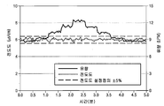
몇몇 실시예에서, 액체 내에 가스의 무기포 용액 또는 실질적인 무기포 용액을 제조하는 기화 방법은, 접촉기의 다공성 요소의 가스 접촉측의 입구 내로 가스를 유동시키는 것과, 접촉기의 다공성 요소의 액체 접촉측의 입구 내로 액체를 유동시키는 것으로서, 액체 접촉측은 다공성 요소와 접촉기 하우징에 의해 가스로부터 분리되는 것인 액체를 유동시키는 것과, 접촉기의 입구 내로 유동하는 가스의 압력에 비교하여 감소된 압력에서 접촉기의 다공성 요소의 가스 접촉측의 출구로부터 가스를 제거하는 것과, 액체 내로 전달된 가스의 일부를 함유하는 액체를 다공성 요소의 액체 접촉측의 출구로부터 제거하는 것을 포함할 수 있다. 방법의 몇몇 실시예는 액체 내에 용해된 가스를 생성하는 데 사용될 수 있고, 여기서 액체 내의 가스의 농도의 안정도는 ±15 퍼센트 이하, 몇몇 경우에 ±5 퍼센트 이하, 또 다른 경우에 ±2 퍼센트 이하이다.In some embodiments, a vaporization method for producing an inorganic or substantially inorganic foam solution of a gas in a liquid comprises flowing a gas into the inlet of the gas contacting side of the porous element of the contactor and the liquid contacting side of the porous element of the contactor. Flowing the liquid into the inlet, the liquid contacting side being a liquid that is separated from the gas by the porous element and the contactor housing, and the porous element of the contactor at a reduced pressure compared to the pressure of the gas flowing into the inlet of the contactor Removing gas from the outlet on the gas-contacting side of the liquid and removing a liquid containing a portion of the gas delivered into the liquid from the outlet on the liquid-contacting side of the porous element. Some embodiments of the method may be used to produce a gas dissolved in a liquid, wherein the stability of the concentration of the gas in the liquid is no more than ± 15 percent, in some cases no more than ± 5 percent, and in other cases no more than ± 2 percent .
몇몇 실시예에서, 액체 내에 가스의 무기포 용액 또는 실질적인 무기포 용액을 제조하기 위한 기화 시스템 또는 장치는 액체 내로 가스를 용해하거나 전달하는 데 사용되는 멤브레인 접촉기를 포함할 수 있다. 기화 시스템은 접촉기에 진입하는 가스 유량을 제어하기 위한 질량 유동 제어기 및/또는 압력 조절기와, 접촉기에 진입하는 액체 유량을 제어하기 위한 액체 유동 제어기를 더 포함할 수 있다. 접촉기의 가스 출구는 몇몇 실시예에서, 접촉기의 입구 내로 유동하는 가스의 압력에 비교하여 감소된 압력에서 접촉기의 다공성 요소의 가스 접촉측으로부터 가스가 제거되는 진공 또는 감소된 압력 소스에 접속될 수 있다. 몇몇 실시예에서, 인라인 농도 모니터가 접촉기의 하류측에 설치되어 액체 내에 용해된 가스의 농도를 측정할 수 있다. 액체 유량이 변화할 때, 가스 유량 및/또는 진공 레벨이 액체 내의 타겟 가스 농도를 유지하기 위해 수동으로 또는 자동으로 조정될 수 있다. 멤브레인 접촉기 내부의 임의의 응축물은 진공 또는 감소된 압력 소스에 의해 제거될 수 있고 응축물 트랩 내에 수집될 수 있다. 기화 시스템은 컴퓨터 판독 가능 저장 매체 상에 저장되고 시스템의 감소된 압력 또는 진공을 차단하지 않고 응축물 트랩 및 배수구를 자동으로 제어하기 위한 컴퓨터 실행 가능 명령을 포함하는 시스템 소프트웨어를 더 포함할 수 있다. 이 구현예는 퍼지 사이클을 위한 필요성을 최소화하고 중단 없는 프로세스를 허용할 수 있다. 진공 또는 감소된 압력은 또한 접촉기 내부의 가스의 부분 압력을 낮추는 기능을 할 수 있고, 이어서 물 내에 용해되는 가스의 양을 낮출 수 있다.In some embodiments, the vaporization system or apparatus for making an inorganic or substantially inorganic solution of gas in a liquid may include a membrane contactor used to dissolve or deliver the gas into the liquid. The vaporization system may further include a mass flow controller and / or a pressure regulator for controlling the gas flow rate entering the contactor, and a liquid flow controller for controlling the liquid flow rate entering the contactor. The gas outlet of the contactor may, in some embodiments, be connected to a vacuum or reduced pressure source where gas is removed from the gas contacting side of the porous element of the contactor at a reduced pressure as compared to the pressure of the gas flowing into the inlet of the contactor. . In some embodiments, an inline concentration monitor may be installed downstream of the contactor to measure the concentration of gas dissolved in the liquid. When the liquid flow rate changes, the gas flow rate and / or vacuum level can be adjusted manually or automatically to maintain the target gas concentration in the liquid. Any condensate inside the membrane contactor may be removed by a vacuum or reduced pressure source and collected in the condensate trap. The vaporization system may further include system software stored on a computer readable storage medium and including computer executable instructions for automatically controlling condensate traps and drains without blocking the reduced pressure or vacuum of the system. This implementation can minimize the need for purge cycles and allow for an uninterrupted process. The vacuum or reduced pressure may also serve to lower the partial pressure of the gas inside the contactor, which in turn may lower the amount of gas dissolved in the water.
본 명세서에 개시된 몇몇 실시예는 액체 내로 하나 이상의 가스를 용해하거나 전달하는 데 사용될 수 있고, 다른 가스와 혼합되지 않고 액체 내로 원하는 가스의 직접적인 분사를 허용한다. 탈이온화(DI)수가 이러한 액체의 예이다. 이는 유리하게는 원하지 않는 희석 가스의 프로세스 오염물을 제거하고, 낮은 가스 소비에 기인하여 작동 비용을 감소시키고, 시스템 구성 및 유지 보수를 간단화한다. 본 명세서에 개시된 실시예는 접촉기의 내부의 액체 응축물 및 유효 접촉 영역의 손실을 감소시키거나 제거함으로써 용해된 가스 안정도 및 일관성을 향상시킬 수 있다. 액체 응축물이 없는 다공성 요소를 유지하기 위해 주기적인 퍼지가 요구되지 않기 때문에, 본 명세서에 개시된 실시예는 도구 휴지 시간 및 유지 보수를 최소화할 수 있다. 낮은 부분 압력에서 공급되는 가스가 접촉기의 다공성 요소를 통해 감소된 압력(낮은 부분 압력에 비교할 때 감소된 압력)에서 액체와 접촉하는 실시예는, 또한 액체 내의 가스의 설정점 농도에 대해 신속한 응답 시간을 제공할 수 있다.Some embodiments disclosed herein can be used to dissolve or deliver one or more gases into a liquid, allowing direct injection of the desired gas into the liquid without mixing with other gases. Deionized (DI) water is an example of such a liquid. This advantageously removes process contaminants of the diluent gas which is undesirable, reduces operating costs due to low gas consumption, and simplifies system configuration and maintenance. Embodiments disclosed herein can improve dissolved gas stability and consistency by reducing or eliminating the loss of liquid condensate and effective contact area inside the contactor. Because no periodic purge is required to maintain the porous element free of liquid condensate, embodiments disclosed herein can minimize tool downtime and maintenance. Embodiments in which the gas supplied at low partial pressure is in contact with the liquid at reduced pressure (reduced pressure as compared to low partial pressure) through the porous element of the contactor also provides a fast response time for the set point concentration of gas in the liquid. Can be provided.
몇몇 실시예에서, 자동화 DI수 기화 시스템은 물 내에 소량의 CO2를 직접 분사하여 어떠한 혼합도 없이 0.5 μS/cm 정도로 낮은 전도도를 갖는 기화된 DI수를 생성하여 유지할 수 있다. 마이크로지멘(μS)은 지멘의 100만분의 1이다. 탈이온화수의 전도도는 마이크로지멘스/cm(또는 micromho/cm) 단위로 측정되는 정도로 매우 작다. 몇몇 실시예에서, 자동화된 DI수 기화 시스템은 10 내지 40 μS/cm의 높은 전도도에서 기화된 DI수를 생성하여 유지할 수 있다. 몇몇 실시예에서, 단일의 자동화된 DI수 기화 시스템은 유량에 따라 다양한 전도도 레벨에서 기화된 DI수를 생성하여 유지할 수 있다. 몇몇 실시예에서, 단일의 자동화된 DI수 기화 시스템은 약 0.5 μS/cm 내지 약 65 μS/cm의 전도도 레벨을 제어할 수 있다.In some embodiments, the automated DI water vaporization system can directly spray a small amount of CO 2 into the water to produce and maintain vaporized DI water with conductivity as low as 0.5 μS / cm without any mixing. Microsiemens (μS) is one millionth of Siemens. The conductivity of deionized water is so small that it is measured in microsiemens / cm (or micromho / cm). In some embodiments, an automated DI water vaporization system can generate and maintain vaporized DI water at high conductivity of 10-40 μS / cm. In some embodiments, a single automated DI water vaporization system may generate and maintain vaporized DI water at various conductivity levels depending on the flow rate. In some embodiments, a single automated DI water vaporization system can control a conductivity level of about 0.5 μS / cm to about 65 μS / cm.
몇몇 실시예에서, 중공 섬유와 같은 다공성 접촉 요소로부터 응축물을 제거하는 것은 타겟 전도도, 물 유량, 가스 유량 등을 포함하는 시스템 조건에 따라 실시예마다 변할 수 있다. DI수 기화 시스템의 몇몇 실시예에서, 멤브레인 기반 접촉기 내부의 응축물을 제거하기 위해 감소된 압력이 인가될 수 있다. 몇몇 실시예에서, 출구 진공 또는 진공 소스가 6 μS/cm의 예시적인 타겟 전도도를 갖고 멤브레인 기반 접촉기의 하류측에 위치한다. 몇몇 실시예에서, 출구 진공은 또한 광범위한 압력 범위에 걸쳐 변동될 수 있는데, 이들 광범위한 압력 모두는 대기압 미만 또는 14.7 입방 인치당 파운드(psi)(101.4 kPa) 미만일 수 있다. 몇몇 실시예에서, 출구 진공은 제거될 수 있다. 예를 들어, 고전도도 시스템은 진공 소스를 필요로 하지 않을 수 있다.In some embodiments, removing condensate from porous contact elements, such as hollow fibers, may vary from embodiment to embodiment depending on system conditions including target conductivity, water flow rate, gas flow rate, and the like. In some embodiments of the DI water vaporization system, reduced pressure may be applied to remove condensate inside the membrane based contactor. In some embodiments, an outlet vacuum or vacuum source is located downstream of the membrane based contactor with an exemplary target conductivity of 6 μS / cm. In some embodiments, the outlet vacuum can also vary over a wide range of pressures, all of which can be below atmospheric pressure or below 14.7 cubic inches (psi) (101.4 kPa). In some embodiments, the outlet vacuum can be removed. For example, high conductivity systems may not require a vacuum source.
몇몇 실시예에서, 감소된 압력은 다공성 요소로부터 응축물을 제거하기에 충분할 수 있다. 자동화된 DI수 기화 시스템의 몇몇 실시예는 40 μS/cm의 예시적인 높은 타겟 전도도를 갖고 CO2 배기 속도를 제어할 수 있다. 몇몇 실시예에서, 출구 진공을 갖는 단일의 자동화된 DI수 기화 시스템은 진공을 사용할 때 그리고 CO2 배기를 사용할 때 소프트웨어 제어를 통해 낮은(10 μS/cm 미만) 및 높은(10 μS/cm 이상) 타겟 전도도 레벨을 성취할 수 있다. 몇몇 실시예에서, 진공은 10 μS/cm 미만인 타겟 전도도를 위해 인가될 수 있다. 몇몇 실시예에서, 진공 레벨은 상이한 전도도 레벨을 위해 조정될 수 있다. 예를 들어, 진공 레벨은 1 μS/cm를 성취하기 위해 증가되고 10 μS/cm를 성취하기 위해 감소될 수 있다. 몇몇 실시예에서, 20 μS/cm를 초과하는 타겟 전도도에 대해, 시스템은 어떠한 진공도 인가하지 않을 수 있다. 이들 경우에, 단지 CO2 배기만이 사용될 수 있다. 몇몇 실시예에서, 10 μS/cm 내지 20 μS/cm인 타겟 전도도에 대해, 진공은 물 유량에 따라 사용될 수 있다.In some embodiments, the reduced pressure may be sufficient to remove condensate from the porous element. Some embodiments of an automated DI water vaporization system can control the CO 2 exhaust rate with an exemplary high target conductivity of 40 μS / cm. In some embodiments, a single automated DI water vaporization system with outlet vacuum is low (less than 10 μS / cm) and high (greater than 10 μS / cm) through software control when using vacuum and when using CO 2 exhaust. The target conductivity level can be achieved. In some embodiments, a vacuum can be applied for a target conductivity of less than 10 μS / cm. In some embodiments, the vacuum level can be adjusted for different conductivity levels. For example, the vacuum level can be increased to achieve 1 μS / cm and decreased to achieve 10 μS / cm. In some embodiments, for target conductivity greater than 20 μS / cm, the system may not apply any vacuum. In these cases, only CO 2 exhaust can be used. In some embodiments, for a target conductivity of 10 μS / cm to 20 μS / cm, vacuum may be used depending on the water flow rate.
자동화된 DI수 기화 시스템의 몇몇 실시예는 이산화탄소가 턴오프(turn-off)되고 질소 퍼프(puff)[N2의 짧은 급격한 러시(rush)]가 시작되어 임의의 응축물을 제거하는 주기적인 유지 보수 사이클을 이용할 수 있다. 여기서, N2는 혼합 또는 희석을 위해 사용되지 않는다. 전도도가 높은 몇몇 용례에서, CO2의 유동은 다공성 요소를 건조하게 유지하기에 충분히 높을 수 있고, 필요하다면 CO2는 턴오프될 수 있고, N2 퍼프가 이용될 수 있다. 몇몇 경우에, N2 퍼프의 시간 길이는 제어되지만 N2 퍼프에 사용된 N2의 양은 제어되지 않는다.Some embodiments of an automated DI water vaporization system provide periodic maintenance in which carbon dioxide is turned off and a nitrogen puff (short abrupt rush of N 2 ) begins to remove any condensate. Maintenance cycles are available. Here, N 2 is not used for mixing or dilution. In some high conductivity applications, the flow of CO 2 may be high enough to keep the porous element dry, CO 2 may be turned off if necessary, and N 2 puffs may be used. In some cases, the time length of N 2 puff is controlled but not the amount of N 2 to N 2 using control puff.
본 명세서에 개시된 기화 시스템 및 방법의 실시예는 임의의 유형의 가스 또는 유체 혼합을 필요로 하지 않고, 희석 가스에 대한 필요성을 제거할 수 있고, 총 가스 소비를 낮출 수 있고, 다양한 반도체 세척 프로세스를 위해 유용할 수 있다. 이들 양태 및 다른 양태는 이하의 설명 및 첨부 도면과 함께 고려될 때 더 양호하게 인식되고 이해될 수 있을 것이다. 이하의 설명은 그 다양한 실시예 및 무수히 많은 특정 상세를 지시하지만 한정적이 아니라 예시적으로 제공된 것이다. 다수의 치환, 수정, 추가 또는 재배열이 본 개시내용의 범주 내에서 이루어질 수 있고, 본 개시내용은 이러한 모든 치환, 수정, 추가 또는 재배열을 포함한다.Embodiments of the vaporization systems and methods disclosed herein do not require any type of gas or fluid mixing, can eliminate the need for diluent gases, lower total gas consumption, and provide a variety of semiconductor cleaning processes. May be useful. These and other aspects will be better appreciated and understood when considered in conjunction with the following description and accompanying drawings. The following description indicates various embodiments and numerous specific details, but is provided by way of example and not by way of limitation. Many substitutions, modifications, additions, or rearrangements may be made within the scope of the present disclosure, and the present disclosure includes all such substitutions, modifications, additions, or rearrangements.
본 개시내용의 실시예는 첨부 도면과 함께 숙독될 때 이하의 상세한 설명을 참조하여 가장 양호하게 이해될 것이다.Embodiments of the present disclosure will be best understood with reference to the following detailed description when read in conjunction with the accompanying drawings.
본 발명에 따르면, 감소된 압력에서 접촉기 내의 액체의 유동 내로 가스를 전달함으로써 액체 내의 가스의 실질적인 무기포 저농도 조성물을 형성하는 것이 가능하다. 또한, 본 발명에 따르면, 공급 액체가 액체 내의 가스의 정상 상태 농도에 신속하게 도달할 수 있으며, 안정하고 적은 편차를 갖는 기화된 용액을 생성할 수 있다.According to the invention, it is possible to form a substantially inorganic low concentration composition of the gas in the liquid by delivering the gas into the flow of the liquid in the contactor at a reduced pressure. In addition, according to the present invention, the feed liquid can quickly reach a steady state concentration of the gas in the liquid, and can produce a vaporized solution having a stable and small deviation.
도 1은 자동화된 기화 시스템의 일 실시예의 개략도.
도 2는 수동 제어를 갖는 기화 시스템의 일 실시예의 개략도.
도 3은 멤브레인 접촉기, 감소된 압력 소스, 저유동 가스 질량 유동 제어기 및 선택적 응축물 트랩을 포함하는 기화 시스템의 일 실시예의 개략도.
도 4는 멤브레인 접촉기, 감소된 압력 소스, 저유동 가스 질량 유동 면적식 유량계 및 선택적 전도도 센서를 포함하는 기화 시스템의 일 실시예의 개략도.
도 5a 및 도 5b는 진공 또는 감소된 압력을 이용하지 않는 경우(도 5a) 및 진공 또는 감소된 압력을 이용하는 경우(도 5b) 액체 내의 가스의 정상 상태 농도 대 시간을 예로서 도시하고 있는 플롯 다이어그램.
도 6은 멤브레인 접촉기, 압력 조절기, 질량 유동 제어기, 프로그램 논리 제어기(PLC) 모듈 및 전도도 센서를 포함하는 기화 시스템의 일 실시예의 개략도.
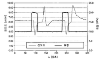
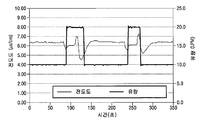
도 7a, 도 7b 및 도 7c는 액체 유량, 시간 및 기화된 액체의 전도도 사이의 관계를 예로서 도시하고 있는 플롯 다이어그램(자동 제어 루프를 가짐).
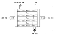
도 8은 멤브레인 접촉기의 일 실시예의 개략도.
도 9는 다양한 전도도 설정점을 유지하는 데 있어서 가스 소비와 액체 유량 사이의 예시적인 관계를 도시하고 있는 플롯 다이어그램.
도 10 내지 도 12b는 전도도 설정점을 유지하는 동안 유량이 변경됨에 따른 전도도와 시간 사이의 예시적인 관계를 도시하고 있는 플롯 다이어그램.1 is a schematic diagram of one embodiment of an automated vaporization system.
2 is a schematic diagram of one embodiment of a vaporization system with manual control;
3 is a schematic diagram of one embodiment of a vaporization system including a membrane contactor, a reduced pressure source, a low flow gas mass flow controller, and an optional condensate trap.
4 is a schematic diagram of one embodiment of a vaporization system including a membrane contactor, a reduced pressure source, a low flow gas mass flow area flow meter, and an optional conductivity sensor.
5A and 5B are plot diagrams illustrating, by way of example, the steady state concentration versus time of a gas in a liquid when not using vacuum or reduced pressure (FIG. 5A) and when using vacuum or reduced pressure (FIG. 5B). .
6 is a schematic diagram of one embodiment of a vaporization system including a membrane contactor, a pressure regulator, a mass flow controller, a programmable logic controller (PLC) module, and a conductivity sensor.
7A, 7B, and 7C are plot diagrams (with automatic control loops) illustrating, as an example, the relationship between liquid flow rate, time, and conductivity of vaporized liquid.
8 is a schematic representation of one embodiment of a membrane contactor.
9 is a plot diagram illustrating an exemplary relationship between gas consumption and liquid flow rate in maintaining various conductivity set points.
10-12B are plot diagrams illustrating an exemplary relationship between conductivity and time as the flow rate changes while maintaining the conductivity set point.
본 발명 및 그 다양한 특징 및 유리한 상세가, 첨부 도면에 도시되고 이하의 설명에서 상세히 설명되어 있는 비한정적인 실시예를 참조하여 더 완전히 설명된다. 잘 알려진 IC 제조 프로세스 및 시작 재료, 반도체 제조 기법 및 설비, 컴퓨터 하드웨어, 및 프로그램 언어와 프로그래밍 기법을 포함하는 소프트웨어 구성 요소의 상세는, 본 개시 내용을 상세히 불필요한 정도로 불명료하게 하지 않기 위해 본 명세서에서 생략되어 있다. 그러나, 당 기술 분야의 숙련자들은 상세한 설명 및 특정예가 바람직한 실시예를 개시하면서도 한정으로서가 아니라 단지 예시로서만 제공되어 있다는 것을 이해해야 한다. 기초의 발명적인 개념(들)의 범주 내의 다양한 치환, 수정, 추가 또는 재배열이 본 개시 내용을 숙독한 후에 당 기술 분야의 숙련자들에게 명백해질 것이다.The invention and its various features and advantageous details are explained more fully with reference to the non-limiting embodiments shown in the accompanying drawings and described in detail in the following description. Details of well-known IC fabrication processes and starting materials, semiconductor fabrication techniques and facilities, computer hardware, and software components, including programming languages and programming techniques, are omitted herein in order not to obscure the present disclosure in detail to the extent that it is not necessary. It is. However, those skilled in the art should understand that the detailed description and the specific examples are provided by way of example only, and not as a limitation. Various substitutions, modifications, additions, or rearrangements within the scope of the inventive concept (s) of the basics will become apparent to those skilled in the art after reading this disclosure.
본 명세서에 개시된 소프트웨어 구현 실시예는 하나 이상의 컴퓨터 판독 가능 저장 매체 상에 상주할 수 있는 적합한 컴퓨터 실행 가능 명령에서 구현될 수 있다. 이 개시 내용 내에서, 용어 "컴퓨터 판독 가능 저장 매체"는 프로세서에 의해 판독될 수 있는 모든 유형의 데이터 저장 매체를 포함한다. 컴퓨터 판독 가능 저장 매체의 예는 임의 접근 메모리, 판독 전용 메모리, 하드 드라이브, 데이터 카트리지, 자기 테이프, 플로피 디스켓, 플래시 메모리 드라이브, 광학 데이터 저장 장치, 콤팩트 디스크 판독 전용 메모리 및 다른 적절한 컴퓨터 메모리 및 데이터 저장 장치를 포함할 수 있다.The software implementation embodiments disclosed herein may be implemented in suitable computer executable instructions that may reside on one or more computer readable storage media. Within this disclosure, the term “computer readable storage medium” includes all types of data storage media that can be read by a processor. Examples of computer readable storage media include random access memory, read only memory, hard drives, data cartridges, magnetic tape, floppy diskettes, flash memory drives, optical data storage devices, compact disk read only memory, and other suitable computer memory and data storage. It may include a device.
본 명세서에 사용될 때, 용어 "포함한다", "포함하는", "구비한다", "구비하는", "갖는다", "갖는" 또는 이들의 임의의 변형은 비한정적인 포함을 커버하는 것으로 의도된다. 예를 들어, 요소들의 리스트를 포함하는 프로세스, 제품, 물품 또는 장치는 반드시 이들 요소들에만 한정되는 것은 아니고, 명시적으로 열거되지 않거나 이러한 프로세스, 물품 또는 장치에 고유한 다른 요소들을 포함할 수 있다. 또한, 명시적으로 반대로 언급되지 않으면, "또는"은 '배제적인 또는'이 아니라 '포함적인 또는'을 칭한다. 예를 들어, 조건 A 또는 B는 이하의 것, 즉 A가 참이고(또는 존재함) B가 거짓이다(또는 존재하지 않음), A가 거짓이고(또는 존재하지 않음) B가 참이다(또는 존재함), A 및 B의 모두가 참이다(또는 존재함) 중 임의의 하나에 의해 충족된다.As used herein, the terms “comprises”, “comprising”, “comprises”, “comprising”, “have”, “having” or any variation thereof are intended to cover non-limiting inclusions. do. For example, a process, product, article, or apparatus that includes a list of elements is not necessarily limited to those elements and may include other elements that are not explicitly listed or unique to such process, article, or apparatus. . Also, unless expressly stated to the contrary, "or" refers to "inclusive or" rather than "exclusive or". For example, the conditions A or B are as follows: A is true (or present), B is false (or not present), A is false (or not present), and B is true (or Present), both A and B are true (or present).
추가적으로, 본 명세서에 제공된 임의의 예 또는 예시는 어떠한 방식으로도 이들이 이용되는 임의의 용어 또는 용어들의 제한, 한정 또는 표현 정의로서 간주되어서는 안 된다. 대신에, 이들 예 또는 예시는 일 특정 실시예에 대해 설명된 것으로서 그리고 단지 예시적인 것으로서 간주되어야 한다. 당 기술 분야의 숙련자들은, 이들 예 또는 예시들이 이용되는 임의의 용어 또는 용어들이 다른 실시예뿐만 아니라 명세서에서 그와 함께 또는 다른 부분에서 제공되거나 제공되지 않을 수 있는 그 구현예 및 적응예를 포함하고, 모든 이러한 실시예는 이 용어 또는 용어들의 범주 내에 포함되도록 의도된 것이라는 것을 이해할 것이다. 이러한 비한정적인 예 및 예시를 나타내는 언어는, 이들에 한정되는 것은 아니지만, "예를 들어", "예로서", "예를 들면", "일 실시예에서" 등을 포함한다.In addition, any example or illustration provided herein is not to be considered in any way as a limitation, limitation or expression definition of any term or terminology in which they are used. Instead, these examples or illustrations should be considered as being described with respect to one particular embodiment and only as illustrative. Those skilled in the art include any embodiment or adaptation in which these terms or terms in which these examples or examples are used may or may not be provided with or in other portions of the specification as well as in other embodiments and It will be appreciated that all such embodiments are intended to be included within this term or category of terms. Languages that illustrate these non-limiting examples and examples include, but are not limited to, "for example," "as an example," "for example," "in one embodiment," and the like.
달리 정의되지 않으면, 본 명세서에 사용되는 모든 기술 용어 및 과학 용어는 당 기술 분야의 숙련자에 의해 통상적으로 이해되는 것과 동일한 의미를 갖는다. 본 명세서에 설명된 것들과 유사하거나 동등한 방법 및 재료가 본 발명의 실시예의 실시 또는 시험에 사용될 수 있다. 본 명세서에 언급된 모든 공보는 그대로 참조로서 포함되어 있다. 본 명세서에서 어느 것도, 본 발명이 선원 발명에 의해 이러한 개시를 선행하는 것으로 자격이 부여되지 않는다는 것을 인정하는 것으로 해석되어서는 안 된다. "선택적" 또는 "선택적으로"는 다음에 설명되는 이벤트 또는 상황이 발생하거나 발생하지 않을 수도 있고, 설명이 이벤트가 발생하는 경우 및 이벤트가 발생하지 않는 경우를 포함한다는 것을 의미한다. 본 명세서의 모든 수치값은 명시적으로 지시되는지에 무관하게 용어 "약"에 의해 수식될 수 있다. 용어 "약"은 일반적으로 당 기술 분야의 숙련자가 열거된 값에 동등한 것으로 고려할 수 있는(즉, 동일한 기능 또는 결과를 가짐) 수의 범위를 칭한다. 몇몇 실시예에서, 용어 "약"은 언급된 값의 ±10%를 칭하고, 다른 실시예에서 용어 "약"은 언급된 값의 ±2%를 칭한다. 조성물 및 방법이 다양한 성분 또는 단계를 "포함하는" 견지에서 설명되면("포함하지만, 이에 한정되는 것은 아닌"의 의미로서 해석됨), 조성물 및 방법은 또한 다양한 성분 및 단계로 "본질적으로 이루어질" 또는 "이루어질" 수 있으며, 이러한 용어는 본질적으로 폐쇄 요소 그룹을 정의하는 것으로서 해석되어야 한다.Unless defined otherwise, all technical and scientific terms used herein have the same meaning as commonly understood by one of ordinary skill in the art. Methods and materials similar or equivalent to those described herein can be used in the practice or testing of embodiments of the present invention. All publications mentioned herein are incorporated by reference in their entirety. Nothing herein is to be construed as an admission that the present invention is not entitled to antedate such disclosure by the source invention. "Optional" or "optionally" means that the event or situation described next may or may not occur, and the description includes cases where an event occurs and when an event does not occur. All numerical values herein may be modified by the term “about” whether explicitly indicated. The term "about" generally refers to a range of numbers that one of ordinary skill in the art can consider to be equivalent to the listed values (ie, have the same function or result). In some embodiments, the term "about" refers to ± 10% of the stated value, and in other embodiments the term "about" refers to ± 2% of the stated value. If the compositions and methods are described in terms of "comprising" various components or steps (interpreted as "including, but not limited to"), the compositions and methods are also "consisting essentially of" various components and steps. Or “consist of,” such terms are to be construed as essentially defining groups of closed elements.
이제, 그 예가 첨부 도면에 도시되어 있는 예시적인 실시예를 상세히 참조한다. 가능한 경우라면 언제나, 동일한 도면 부호는 동일한 또는 유사한 부분(요소)을 칭하도록 도면의 전체에 걸쳐 사용될 것이다.Reference is now made in detail to the example embodiments shown in the accompanying drawings. Wherever possible, the same reference numbers will be used throughout the drawings to refer to the same or similar parts (elements).
본 명세서에 개시된 기화 시스템 및 방법의 실시예는 액체 내에 가스의 무기포 또는 실질적인 무기포 용액을 생성할 수 있다. 이와 같이 생성된 기화된 액체는 액체 내에 저농도의 가스를 가질 수 있다. 몇몇 실시예에서, 공급 가스가 공급 액체에 도입된다. 몇몇 실시예에서, 공급 가스는 이산화탄소(CO2)이고, 공급 액체는 탈이온화(DI)수(H2O)이다. DI수가 예시적인 공급 액체로서 본 명세서에 설명되었지만, 당 기술 분야의 숙련자들은 공급 액체가 DI수에 한정되는 것은 아니고, 본 명세서에 개시된 실시예가 다른 유형의 공급 액체에 대해 채택되거나 다른 방식으로 구현될 수도 있다는 것을 이해할 수 있을 것이다. 유사하게, CO2가 예시적인 공급 가스로서 본 명세서에 설명되었지만, 당 기술 분야의 숙련자들은 공급 가스가 CO2에 한정되는 것은 아니고, 본 명세서에 개시된 실시예가 다른 유형의 공급 가스에 대해 채택되거나 다른 방식으로 구현될 수 있다는 것을 이해할 수 있을 것이다. 몇몇 실시예에서, CO2는 직접 분사에 의해 기화 시스템 내의 DI수에 도입된다. 이 직접 분사법은 H2O 및/또는 질소(N2)와 같은 불활성 가스와 CO2를 혼합하는 것을 필요로 하지 않는다.Embodiments of the vaporization systems and methods disclosed herein can produce an inorganic or substantially inorganic solution of a gas in a liquid. The vaporized liquid thus produced may have a low concentration of gas in the liquid. In some embodiments, the feed gas is introduced into the feed liquid. In some embodiments, the feed gas is carbon dioxide (CO 2 ) and the feed liquid is deionized (DI) water (H 2 O). Although DI water is described herein as an exemplary feed liquid, those skilled in the art are not limited to DI water, and the embodiments disclosed herein may be employed or otherwise implemented for other types of feed liquids. It will be appreciated that it may. Similarly, although CO 2 has been described herein as an exemplary feed gas, those skilled in the art will appreciate that the feed gas is not limited to CO 2 , and that the embodiments disclosed herein are employed for other types of feed gases or It will be appreciated that it may be implemented in a manner. In some embodiments, CO 2 is introduced into DI water in the vaporization system by direct injection. This direct injection method does not require mixing CO 2 with an inert gas such as H 2 O and / or nitrogen (N 2 ).
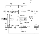
도 1은 폐루프 제어를 갖는 자동화된 기화 시스템의 일 실시예의 개략도를 도시하고 있다. 시스템(100)은 가스 소스(110), 액체 소스(120), 시스템 제어기(130), 접촉기(160), 질량 유동 제어기(MFC) 또는 압력 제어기(140) 및 진공 소스(180)를 포함한다. 시스템 제어기(130)는 접촉기 내로의 가스의 유동에 비례하는 출력 신호[MFC(140)로부터의 제어기 측정 신호(142)], 접촉기의 액체 출구에서의 액체 내의 가스의 양에 비례하는 출력 신호[농도 모니터(170)로부터의 농도 측정 신호(172)], 또는 접촉기 내로의 액체의 유동에 비례하는 출력 신호[액체 유량계(150)로부터의 FIW 유량 측정 신호(152)]를 수신하도록(예를 들어, 이들에 한정되는 것은 아니지만, 유선, 무선 등을 사용하여) 구성된다. 이들 신호는 유선, 무선, 광 섬유, 이들의 조합 등에 의해 이동될 수 있다.1 shows a schematic diagram of one embodiment of an automated vaporization system with closed loop control.
접촉기(160)는 가스 접촉측 및 액체 접촉측을 포함할 수 있다. 가스 접촉측은 가스 입구 및 가스 출구를 가질 수 있다. 액체 접촉측은 액체 입구 및 액체 출구를 가질 수 있다. 액체 입구는 탈가스될 수 있는 공급 액체를 위해 구성될 수 있다. 액체 출구는 공급 액체보다 액체 내에 더 많은 총 가스를 함유하는 액체 조성물을 위해 구성될 수 있다. 이 예에서, DI수는 공급 액체이고 CO2는 공급 가스이며, 이에 따라 기화된 DI수 또는 용해된 CO2 가스를 갖는 DI수를 함유하는 액체 조성물을 생성한다.
몇몇 실시예에서, 접촉기(160)는 다공성 요소를 포함할 수 있다. 다공성 요소는 접촉기의 하우징 내에 장착될 수 있다. 몇몇 실시예에서, 접촉기의 다공성 요소는 액체 접촉측 및 가스 접촉측을 포함할 수 있다. 몇몇 실시예에서, 접촉기의 다공성 요소의 액체 접촉측은 다공성 요소와 접촉기 하우징에 의해 가스로부터 분리된다. 몇몇 실시예에서, 접촉기는 퍼플루오로알콕시(PFA) 중공 섬유 멤브레인 기반 접촉기이다. 몇몇 실시예에서, 다공성 요소는 다공성 멤브레인일 수 있다. 몇몇 실시예에서, 다공성 멤브레인은 약 35 psi(241.3 kPa) 초과의 기포점을 가질 수 있고, 몇몇 실시예에서 80 psi(551.6 kPa) 초과의 기포점을 가질 수 있고, 또 다른 실시예에서 100 psi(689.5 kPa) 초과의 기포점을 가질 수 있다. 기포점은, 소정의 유체 및 기공 크기에 대해, 일정한 습윤에 의해 기공을 통해 공기 기포를 가압하는 데 요구되는 압력이 기공 직경의 크기에 반비례한다는 사실에 기초하여 필터 요소 내의 단일의 최대 기공의 크기의 상대적인 척도를 얻기 위해 사용된다. 즉, 기포의 제1 스트림이 발생하는 점이 최대 기공이다. 표준 기포점 시험 절차는 시험 유체로서 이소프로필 알코올(IPA)을 사용하고, 따라서 기포점은 종종 IPA 기포점이라 칭한다.In some embodiments,
MFC(140)는 가스 유동 제어기의 예이다. 적합한 가스 유동 제어기의 추가의 예는, 이들에 한정되는 것은 아니지만, 면적식 유량계, 압력 제어기, 오리피스, 밸브와 오리피스의 조합, 조정 가능 밸브 등을 포함할 수 있다. 가스 유동 제어기는 접촉기의 가스 입구에 유체로 연통된다.
액체 유량계(150)가 액체 유동 제어기의 예이다. 적합한 액체 유동 제어기의 추가의 예는, 이들에 한정되는 것은 아니지만, 면적식 유량계, 압력 제어기, 오리피스, 밸브와 오리피스의 조합, 조정 가능 밸브 등을 포함할 수 있다. 액체 유동 제어기는 접촉기의 액체 접촉측에 유체로 연통된다.
진공 소스(180)는 접촉기의 가스 접촉 표면에 감소된 압력을 제공할 수 있고, 접촉기의 가스 출구에 유체로 연통될 수 있다. 적합한 진공 소스(180)의 예는, 이들에 한정되는 것은 아니지만, 진공 펌프와 같은 압력 제어기, 밸브 및 진공 펌프, 벤츄리관, 압력 게이지 및 제어기 등을 포함할 수 있다. 몇몇 실시예에서, 진공 소스(180)는 접촉기의 다공성 요소의 가스 접촉측의 액체 응축물을 제거하거나 증발시킬 수 있다.The
시스템 제어기(130)는 가스 소스(110)로부터 접촉기(160)로의 가스(112)의 유동, 접촉기(160)로부터 액체(126) 내의 가스(112)의 농도 또는 양, 접촉기(160) 내로의 액체 유동 또는 이들의 조합을 그 대응 설정점 값에 비교하여 기화된 액체(126) 내의 가스(112)의 설정점 농도를 생성할 수 있다. 시스템 제어기(130)는 접촉기(160) 내로의 가스의 유동을 변경하거나, 접촉기(160)의 출구에서 가스의 압력을 변경하거나, 접촉기(160) 내로의 액체(122)의 유동을 변경하거나 또는 이들 변경의 조합을 수행하는 데 사용되어 액체(126)(액체 조성물) 내의 가스의 농도를 설정점 농도의 15% 이내로, 몇몇 경우에 10% 이내로, 다른 경우에 5% 이내로, 또 다른 경우에 3% 이내로 유지할 수 있게 하는 출력 신호(132)를 생성할 수 있다. 설정점 농도 내의 편차가 작을수록, 액체 조성물을 이용하는 제조 프로세스의 안정성 및 재현성이 더 커진다.The
압력 트랜스듀서(도 3 내지 도 4 및 도 6 참조)가 접촉기와 진공 소스 사이에서 접촉기의 가스 출구에 위치될 수 있다. 압력 트랜스듀서는 진공 소스의 일부일 수 있다. 진공 소스는 시스템 제어기에 입력을 제공할 수 있고, 시스템 제어기로부터 출력을 수신하여 감소된 압력을 변경하거나, 배기 가스 및 응축물(162)을 통기하거나, 또는 이들의 조합을 수행할 수 있다. 도 1에 도시되어 있는 바와 같이, 물 내에 용해된 CO2의 양은 CO2의 부분 압력을 조정함으로써 제어될 수 있다. 선택적으로, 액체 내로 전달된 가스의 농도를 측정하기 위해 접촉기의 액체 출구에 센서가 접속될 수 있다. 물 전기 전도도는 물 내의 CO2의 농도에 직접 비례하고, 물 내의 CO2 농도의 척도로서 사용될 수 있다.A pressure transducer (see FIGS. 3-4 and 6) may be located at the gas outlet of the contactor between the contactor and the vacuum source. The pressure transducer can be part of a vacuum source. The vacuum source may provide an input to the system controller and receive output from the system controller to change the reduced pressure, vent the exhaust and
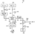
도 2는 수동 제어를 이용하는 기화 시스템의 일 실시예의 개략도를 도시하고 있다. 시스템(200)은 가스 소스(210), 액체 소스(220), 질량 유동 제어기(MFC) 또는 압력 제어기(240), 액체 유량계(250), 접촉기(260), 농도 모니터(270) 및 진공 소스(280)를 포함한다. 가스 소스(210)로부터의 가스(212)가 MFC(240)를 통해 제어될 수 있다. 액체 소스(220)로부터의 액체(222)의 유량은 유량 측정 신호(252)를 생성하는 액체 유량계(250)에서 측정될 수 있다. 진공 소스(280)가 접촉기(260)로부터 배기 가스 및 응축물(262)을 제거하는 데 이용된다. 접촉기(260)로부터 나오는 기화된 액체(226)의 농도는 농도 모니터(270)에 의해 모니터링될 수 있다. 이하의 표 1은 시스템(200)의 실시예를 이용한, DI수 내에 용해된 저농도의 CO2에 대한 통상적인 성능 결과의 예이다.2 shows a schematic diagram of one embodiment of a vaporization system using manual control.
(LPM)DI water flow rate
(LPM)
(sccm)CO 2 gas flow rate
(sccm)
(μS/cm)conductivity
(μS / cm)
안정도conductivity
Stability
압력(psi)DI number
Pressure (psi)
도 3은 가스 소스(310), 액체 소스(320), 저유동 가스 질량 유동 제어기(340), 멤브레인 접촉기(360), 전도도 센서(372), 진공 소스(380) 및 선택적 응축물 트랩(364)을 포함하는 기화 시스템(300)의 일 실시예의 개략도를 도시하고 있다. 시스템(300)은 안정적인 물 전도도를 유지하기 위한 선택적인 폐루프 제어부를 더 포함할 수 있다. 진공 소스(380)는 감소된 압력(즉, 대기압 미만)에서 일정한 진공 스윕(sweep)을 제공하여 접촉기(360) 내부의 응축을 제거하고 액체(322) 내에 가스(312)를 전달하기 위한 낮은 부분 압력을 제공할 수 있다. 가스(312)가 제1 압력에서 접촉기(360)에 공급되는 경우에, 진공 소스(380)는 제1 압력보다 낮은 제2 압력을 접촉기(360)에 공급할 수 있어, 가스(312)가 감소된 압력에서 접촉기(360)를 통해 액체(322) 내로 전달될 수 있게 한다. 몇몇 실시예에서, 접촉기(360)는 미국 미네소타주 차스카 소재의 엔테그리스 인크(Entegris, Inc.)로부터 입수 가능한 pHasor![]()
![]()
도 3에 도시되어 있는 선택적인 응축물 트랩(364)은, 진공 소스(380)에 의해 발생되거나 유발된 진공 또는 감소된 압력을 붕괴시키지 않고 배기 가스 및 응축물(362)을 제거하기 위해 선택적인 자동 배수 기능을 갖는 다양한 밸브(304, 306, 308)를 포함한다. 예를 들어, 밸브(304, 306)는 진공 차단 밸브일 수 있고, 밸브(308)는 응축물 트랩(364)으로부터 배기 가스 및 응축물(362)을 배출하기 위한 배수 밸브일 수 있다. 도 3은 또한 예시적인 목적으로, 진공 게이지(396), 액체 압력 게이지(394) 및 전도도 센서(372)를 포함하는 선택적인 구성 요소를 도시하고 있다. 전도도 센서(372)는 기화된 액체(326) 내의 가스(312)의 농도를 측정하기 위해 접촉기(360)의 액체 출구에 접속될 수 있다.The
몇몇 실시예에서, 전도도 센서(372)로부터의 출력은 기화된 액체(326) 내의 가스(312)의 농도를 설정점 또는 타겟 농도와 비교하는 데 이용될 수 있다. 예를 들어, 시스템 제어기는 전도도 센서(372)에 의해 측정된 바와 같은 기화된 액체(326) 내의 가스(312)의 양에 비례하는 출력 신호를 수신하도록(유선, 무선, 광 등을 통해) 구성될 수 있다. 다양한 실시예에서, 제어기는 센서 출력을 설정점 농도와 비교할 수 있고, 기화된 액체(326) 내의 가스(312)의 농도를 타겟 레벨로 유지하기 위해 접촉기 내로의 가스의 유동을 변경하기 위한 출력 신호, 접촉기 내로의 액체의 유동을 변경하기 위한 출력 신호, 접촉기의 가스 출구에서의 압력을 변경하기 위한 출력 신호 또는 이들의 조합을 생성할 수 있다. 몇몇 실시예에서, 타겟 레벨은 설정점 농도이거나 설정점 농도에 근접할 수 있다. 몇몇 실시예에서, 타겟 레벨은 설정점 농도의 범위 내에 있을 수 있다. 이러한 범위의 예는, 이들에 한정되는 것은 아니지만, 15%, 10%, 5% 및 3%를 포함할 수 있다.In some embodiments, the output from the conductivity sensor 372 can be used to compare the concentration of the
본 명세서에 개시된 실시예에서, 가스 유동 제어기는 가스 소스와 함께 작동하여 낮은 부분 압력에서 멤브레인 접촉기에 공급 가스를 제공할 수 있다. 용례 및 다양한 실시예에 따라, 감소된 압력은 40 kPa, 12 kPa, 6 kPa 또는 그 이하일 수 있다. 몇몇 실시예에서, 액체의 표준 입방 센티미터(sccm) 단위의 액체 유동 제어기의 유량 범위에 비교되는, 가스의 표준 입방 센티미터 단위의 가스 유동 제어기의 유량 범위의 비율은 0.02 이하, 몇몇 경우에 0.002 이하, 다른 경우에 0.0005 이하, 또 다른 경우에 0.00025 이하이다. 감소된 압력의 소스와 조합된 가스 유동 제어기에 대한 작은 가스 유량 범위는 낮은 부분 압력의 가스를 액체에 제공할 수 있도록 하고, 액체 유동에 대한 가스의 낮은 비율은 또한 액체에 낮은 농도의 가스를 제공하는 것을 돕는다.In the embodiments disclosed herein, the gas flow controller can work with a gas source to provide feed gas to the membrane contactor at low partial pressure. Depending on the application and various embodiments, the reduced pressure may be 40 kPa, 12 kPa, 6 kPa or less. In some embodiments, the ratio of the flow rate range of the gas flow controller in standard cubic centimeters of gas to the flow rate range in standard cubic centimeters of liquid (sccm) is 0.02 or less, in some cases 0.002 or less, In other cases, 0.0005 or less, and in other cases, 0.00025 or less. The small gas flow range for the gas flow controller in combination with the source of reduced pressure allows to provide low partial pressure gas to the liquid, and the low proportion of gas to liquid flow also provides low concentration of gas to the liquid. To help.
몇몇 실시예에서, 액체 내에 가스의 무기포 또는 실질적인 무기포 용액을 제조하는 방법은, 낮은 부분 압력에서 멤브레인 접촉기의 다공성 요소의 가스 접촉측의 입구 내로 가스를 유동시키는 것과, 멤브레인 접촉기의 다공성 요소의 액체 접촉측의 입구 내로 탈가스될 수 있는 공급 액체를 유동시키는 것을 포함할 수 있다. 몇몇 실시예에서, 이 방법은 감소된 압력에서 멤브레인 접촉기의 가스 출구로부터 배기 가스를 제거하는 것과, 공급 액체 내로 감소된 압력에서 가스의 일부를 전달하는 것과, 무기포 또는 실질적인 무기포이고 공급 액체보다 더 많은 가스를 함유하는 액체 조성물을 멤브레인 접촉기의 액체 출구로부터 제거하는 것을 더 포함할 수 있다.In some embodiments, a method of making an inorganic or substantially inorganic solution of a gas in a liquid comprises flowing a gas at a low partial pressure into the inlet of the gas contacting side of the porous element of the membrane contactor, Flowing a feed liquid that can be degassed into the inlet on the liquid contact side. In some embodiments, the method includes removing the exhaust gas from the gas outlet of the membrane contactor at a reduced pressure, delivering a portion of the gas at a reduced pressure into the feed liquid, an inorganic or substantially inorganic, and It may further comprise removing the liquid composition containing more gas from the liquid outlet of the membrane contactor.
본 명세서에 개시된 기화 시스템의 몇몇 실시예는, 가스 유동이 0 표준 분당 입방 센티미터로부터 1 표준 분당 입방 센티미터로 변경되고 접촉기의 가스 출구에서 측정된 감소된 압력이 6 kPa(-28 inHg)일 때 22℃에서 DI수가 분당 2 리터로 멤브레인 접촉기를 통해 유동하는 상태에서, 120초 이내에 탈이온화수 내에 정상 상태 농도의 이산화탄소를 제공할 수 있는 것을 특징으로 한다. 이 경우, CO2는 공급 가스의 예이고, DI수가 공급 액체의 예이다. 정상 상태에서, 시스템은 물 내의 이산화탄소의 농도의 ±5% 미만 편차를 갖는 무기포 또는 실질적인 무기포 용액 또는 액체 조성물을 생성할 수 있다.Some embodiments of the vaporization system disclosed herein change the gas flow from 0 standard cubic centimeters per minute to 1 standard cubic centimeters per minute and the reduced pressure measured at the gas outlet of the contactor is 6 kPa (-28 inHg). With DI water flowing through the membrane contactor at 2 liters per minute, it is possible to provide a steady state concentration of carbon dioxide in deionized water within 120 seconds. In this case, CO 2 is an example of the supply gas, and DI water is an example of the supply liquid. In steady state, the system may produce an inorganic or substantially inorganic solution or liquid composition having a deviation of less than ± 5% of the concentration of carbon dioxide in the water.
몇몇 실시예에서, 시스템은 접촉기 내로의 가스의 유동에 비례하는 출력 신호, 가스 출구에서의 압력에 비례하는 출력 신호 및 접촉기 내로의 액체의 유동에 비례하는 출력 신호를 포함하는 신호를 수신하도록 구성된 시스템 제어기를 포함할 수 있다. 제어기는 대응 신호에 대한 설정점 값을 저장하고/저장하거나 이 설정점 값에 대해 접근할 수 있다. 제어기는 접촉기 내로의 공급 가스의 유동, 접촉기 내로의 공급 액체의 유동, 접촉기의 가스 출구에서의 압력, 또는 이들 신호의 조합을 이들의 대응 설정점 값과 비교하고, 기화된 액체 내의 가스의 설정점 농도를 생성할 수 있다. 추가적으로, 제어기는 타겟 레벨에서 기화된 액체 내의 가스의 농도를 유지하기 위해 접촉기 내로의 공급 가스의 유동을 변경하기 위한 출력 신호, 접촉기 내로의 공급 액체의 유동을 변경하기 위한 출력 신호, 접촉기의 가스 출구에서의 압력을 변경하기 위한 출력 신호, 또는 이들의 조합을 생성할 수 있다. 몇몇 실시예에서, 타겟 레벨은 설정점 농도이거나 설정점 농도에 근접할 수 있다. 몇몇 실시예에서, 타겟 레벨은 설정점 농도의 15% 이내, 몇몇 경우에 설정점 농도의 5% 이하 이내, 다른 경우에 설정점 농도의 3% 이하 이내일 수 있다.In some embodiments, the system is configured to receive a signal comprising an output signal proportional to the flow of gas into the contactor, an output signal proportional to the pressure at the gas outlet, and an output signal proportional to the flow of liquid into the contactor. It may include a controller. The controller may store and / or access the setpoint value for the corresponding signal. The controller compares the flow of feed gas into the contactor, the flow of feed liquid into the contactor, the pressure at the gas outlet of the contactor, or a combination of these signals with their corresponding set point values, and the set point of the gas in the vaporized liquid Concentration can be generated. In addition, the controller may include an output signal for changing the flow of the supply gas into the contactor to maintain the concentration of the gas in the vaporized liquid at the target level, an output signal for changing the flow of the supply liquid into the contactor, and the gas outlet of the contactor. It is possible to generate an output signal, or a combination thereof, to change the pressure at. In some embodiments, the target level may be at or close to the setpoint concentration. In some embodiments, the target level may be within 15% of the setpoint concentration, in some cases within 5% of the setpoint concentration, and in other cases within 3% of the setpoint concentration.
시스템은 접촉기의 액체 출구에 접속된 센서를 더 포함할 수 있다. 센서는 액체 내의 가스의 양에 비례하는 신호를 생성할 수 있다. 몇몇 실시예에서, 시스템 제어기는 센서로부터 신호를 수신하도록 구성될 수 있다. 시스템 제어기는 액체 내의 가스의 설정점 농도와 센서 출력을 비교할 수 있고, 설정점 농도의 범위이거나 이 범위 내에 있을 수 있는 타겟 레벨에서 기화된 액체 내의 가스의 농도를 유지하기 위해 접촉기 내로의 공급 가스의 유동을 변경하기 위한 출력 신호, 접촉기 내로의 공급 액체의 유동을 변경시키기 위한 출력 신호, 접촉기의 가스 출구에서의 압력을 변경시키기 위한 출력 신호, 또는 이들의 조합을 생성할 수 있다. 전술된 바와 같이, 소량의 용해된 가스로 물의 도핑을 제어하는 것은 어렵기 때문에, 낮은 농도의 용해된 가스를 갖는 물을 생성하여 유지하는 것이 종래의 기화 시스템에서 어려울 수 있다. 액체 내로 전달된 가스의 양의 낮은 편차를 갖는 기화된 액체 조성물을 사용하는 것은 제조 프로세스에 더 큰 안정성 및 더 적은 편차를 제공할 수 있고, 이에 의해 종래의 기화 시스템에 의해 종종 직면하게 되는 어려움을 극복한다.The system may further comprise a sensor connected to the liquid outlet of the contactor. The sensor may generate a signal proportional to the amount of gas in the liquid. In some embodiments, the system controller can be configured to receive a signal from the sensor. The system controller can compare the sensor output with the set point concentration of the gas in the liquid and determine the concentration of the feed gas into the contactor to maintain the concentration of the gas in the vaporized liquid at a target level that may be within or within the set point concentration. An output signal for changing the flow, an output signal for changing the flow of the feed liquid into the contactor, an output signal for changing the pressure at the gas outlet of the contactor, or a combination thereof. As mentioned above, it is difficult to control the doping of water with a small amount of dissolved gas, so that producing and maintaining water with a low concentration of dissolved gas can be difficult in conventional vaporization systems. Using a vaporized liquid composition with a low variation in the amount of gas delivered into the liquid can provide greater stability and less variation in the manufacturing process, thereby avoiding the difficulties often encountered by conventional vaporization systems. Overcome
도 4는 기화 시스템의 비한정적인 실시예의 개략도를 도시하고 있다. 시스템(400)은 접촉기(460), 접촉기(460)에 공급 가스(412)를 공급하기 위한 가스 소스(410), 접촉기(460)에 공급 액체(422)를 공급하기 위한 액체 소스(420) 및 접촉기(460)에 진공 또는 감소된 압력을 제공하기 위한 진공 소스(480)를 포함할 수 있다. 접촉기(460)는 전술된 바와 같이 멤브레인 기반 접촉기일 수 있다. 압력 게이지(492) 및 저유동 가스 질량 유동 면적식 유량계(440)가 공급 가스(412)를 모니터링하고 조절하기 위한 멤브레인 접촉기(460)와 가스 소스(410) 사이에 위치될 수 있다. 일 실시예에서, 면적식 유량계(440)는 0 내지 11 표준 시간당 입방 피트(SCFH)의 작동 범위를 가질 수 있다. 일 실시예에서, 가스 소스(410)는 약 1 psi(6.9 kPa)에서 CO2를 공급할 수 있다. 압력 게이지(494) 및 밸브(402)는 공급 액체(422)를 모니터링하고 제어하기 위한 멤브레인 접촉기(460)와 액체 소스(420) 사이에 위치될 수 있다. 일 실시예에서, 액체 소스(420)는 약 0.5 내지 3 gpm에서 DI수를 공급할 수 있다. 일 실시예에서, 멤브레인 접촉기(460)의 입구에서의 DI수 온도는 약 23.5 내지 24.5℃이다. 압력 게이지(460)는, 멤브레인 접촉기(460)로부터 배기 가스 및 응축물(462)을 제거하는 데 있어서 소스(480)에 의해 생성된 감소된 압력을 모니터링하기 위한 멤브레인 접촉기(460)와 감소된 압력 소스(480) 사이에 위치될 수 있다.4 shows a schematic diagram of a non-limiting embodiment of a vaporization system.
시스템(400)은 멤브레인 접촉기(460)의 액체 출구로부터 기화된 액체 내의 가스(412)의 농도를 분석하기 위한 선택적 분석기(476)에 접속될 수 있는 선택적인 전도도 센서(472)를 더 포함할 수 있다. 일 실시예에서, 전도도 센서(472)는 허니웰(Honeywell) 3905 전도도 셀일 수 있고, 분석기(476)는 허니웰 UDA 분석기일 수 있다. 도 4에 도시된 예에서, 기화된 액체는 배수구로 안내된다. 면적식 유량계는 기화된 액체의 유동을 측정하기 위해 전도도 센서(472)와 배수구 사이에 위치될 수 있다. 다른 실시예에서, 기화된 액체는 분배점 또는 시스템 하류측 기화 시스템(400)으로 안내될 수 있다.
일 실시예에서, 감소된 압력 소스(480)는 멤브레인 접촉기(460)의 다공성 요소에 낮은 총 압력의 CO2 가스를 제공할 수 있다. 일 실시예에서, 감소된 압력 소스(480)는 -28 inHg에서 진공 레벨을 제공할 수 있다. 일 실시예에서, 감소된 압력 소스(480)는 접촉기 내부의 응축물을 제거하기 위해 6 kPa에서 일정한 진공 스윕을 제공할 수 있다. 일 실시예에서, 감소된 압력 소스(480)는 미국 미네소타주 차스카 소재의 엔테그리스 인크로부터 입수 가능한 벤츄리형 진공 발생기일 수 있다. 이하에 더 설명되는 바와 같이, 다공성 요소의 가스 접촉측 상에서 장치 내의 압력을 감소시킴으로써, 액체 내로 전달되는 가스의 양의 편차가 감소될 수 있다.In one embodiment, the reduced
다공성 요소의 가스 접촉측의 장치에서의 압력을 감소시키는 것은, 또한 접촉기를 통해 유동하는 액체 내로 전달된 가스의 양에 대해 정상 상태에 도달할 때까지의 시간을 감소시키는 것으로 판명되었다. 본 명세서에서, 정상 상태에 도달할 때까지의 빠른 시간은 10분 미만의 시간, 몇몇 경우에 2분 미만의 시간, 또 다른 경우에 1분 미만의 시간을 칭하고, 여기서 0 내지 1 표준 분당 입방 센티미터(sccm) 또는 그 이상의 가스 유량의 증가는 액체 내의 가스의 정상 상태 농도를 초래한다. 몇몇 실시예에서, 액체 증기압에 따라, 접촉기의 가스 출구의 하류측에서 측정된 압력은 40 kPa(약 -18 inHg) 이하, 몇몇 경우에 40 kPa 내지 5 kPa(약 -28 inHg), 또 다른 경우 15 kPa 내지 5 kPa일 수 있다. 정상 상태에 도달할 때까지의 빠른 시간은 ±15 퍼센트 이하, 몇몇 경우에 ±5 퍼센트 이하, 또 다른 경우에 ±3 퍼센트 이하인 농도 편차를 포함한다. 액체 내의 가스의 정상 상태 농도에 도달하는 능력은, 시동으로부터 프로세스 사이클 시간을 감소시킬 수 있고 또한 사용되지 않을 때 가스를 턴오프함으로써 사용자가 가스를 보존할 수 있기 때문에 유리하다.Reducing the pressure in the device on the gas contacting side of the porous element has also been found to reduce the time to reach steady state with respect to the amount of gas delivered into the liquid flowing through the contactor. As used herein, a fast time to reaching steady state refers to a time of less than 10 minutes, in some cases less than 2 minutes, and in other cases less than 1 minute, where 0 to 1 standard cubic centimeters per minute An increase in gas flow rate (sccm) or higher results in a steady state concentration of gas in the liquid. In some embodiments, depending on the liquid vapor pressure, the pressure measured downstream of the gas outlet of the contactor is 40 kPa (about -18 inHg) or less, in some
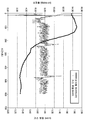
도 5a 및 도 5b는 진공 또는 감소된 압력을 이용하지 않는 경우(도 5a) 및 진공 또는 감소된 압력을 이용하는 경우(도 5b) 액체 내의 가스의 정상 상태 농도 대 시간을 예로서 도시하고 있는 플롯 다이어그램이다. 더 구체적으로는, 도 5a는, 이산화탄소 유동의 0 sccm 내지 1 sccm의 단계적 변화, 22.2℃에서 2 lpm 액체 유동수, 약 8.5초에서 시작하는 이산화탄소 가스 유동(시간 0 내지 8.5초 동안 질량 유동 오프셋이 존재하지만 유동은 0임), 약 81초에서 1 sccm 설정점에서 안정한 가스 유동, 2.88 Mohm-cm에서 약 413초에서 대략 안정한 물 내의 CO2의 농도에 대해, 접촉기 가스 출구에서의 진공 또는 감소된 압력을 이용하지 않는 경우 액체 내의 가스의 정상 상태 농도 대 시간을 도시하고 있다. 비저항의 편차는 약 413초(정상 상태) 후에 약 2.61 내지 약 2.88 Mohm-cm(저점으로부터 고점까지)이다. 가스 온(on) 상태로부터 정상 상태에 도달할 때까지의 시간(8.5초 내지 413초는 약 405초 또는 6.75분임), 즉 1 sccm의 안정한 가스 온(on) 유동으로부터 정상 상태에 도달할 때까지의 시간은 81초 내지 413초 또는 약 5.5분인 332초이다. 액체 내의 가스의 양의 편차는 약 5.1%이다[그래프로부터 약 2.74 Mohm-cm의 추정 평균 비저항; 2.88(고)-2.74(추정 평균)=0.14 M-ohm; (0.14/2.74)*100=5.1%].5A and 5B are plot diagrams illustrating, by way of example, the steady state concentration versus time of a gas in a liquid when not using vacuum or reduced pressure (FIG. 5A) and when using vacuum or reduced pressure (FIG. 5B). to be. More specifically, FIG. 5A shows a gradual change in carbon dioxide flow from 0 sccm to 1 sccm, 2 lpm liquid flow at 22.2 ° C., carbon dioxide gas flow starting at about 8.5 seconds (mass flow offset for
도 5b는, 이산화탄소 유동의 0 sccm 내지 1 sccm의 단계적 변화, 22.2℃에서 2 lpm 액체 유동수, 약 40초에서 시작하는 이산화탄소 가스 유동(0 내지 40초 동안 질량 유동 오프셋이 존재하지만 유동은 0임), 약 67초에서 1 sccm 설정점에서의 안정한 가스 유동, 1.76 Mohm-cm에서 약 144초에서의 대략 안정한 물 내의 CO2의 농도에 있어서 접촉기 가스 출구에서의 진공 또는 감소된 압력을 이용하는 경우 액체 내의 가스의 정상 상태 농도 대 빠른 응답 시간을 도시하고 있다. 비저항의 편차는 도 6a의 진공이 없는 예에 대해 작은 약 144초(정상 상태) 후에 약 1.66 내지 약 1.76 Mohm-cm(저점으로부터 고점까지)이다. 가스 온 상태로부터 정상 상태에 도달할 때까지의 시간(40 내지 144초는 120초보다 작은 약 104초임), 즉 1 sccm의 안정한 가스 온 상태 유동으로부터 정상 상태에 도달할 때까지의 시간은 67초 내지 144초 또는 1.5분보다 작은 77초이다. 액체 내의 가스의 양의 편차는 약 3% 이하이다[그래프로부터 약 1.71 Mohm-cm의 추정 평균 비저항; 1.76(고)-1.71(추정 평균)=0.05 M-ohm; (0.05/1.71)*100=2.9%]. 도 5a 및 도 5b에 도시되어 있는 바와 같이, 접촉기에 감소된 압력의 가스를 제공하는 것은, 시동 시간을 단축시킬 수 있고, 농도 편차를 낮출 수 있고, 정상 상태에 도달할 때까지의 빠른 시간을 성취할 수 있다.FIG. 5B shows a gradual change from 0 sccm to 1 sccm of carbon dioxide flow, 2 lpm liquid flow at 22.2 ° C., carbon dioxide gas flow starting at about 40 seconds (with mass flow offset for 0 to 40 seconds but flow is zero) Stable gas flow at 1 sccm set point at about 67 seconds, concentration of CO 2 in approximately stable water at about 144 seconds at 1.76 Mohm-cm, using vacuum or reduced pressure at the contactor gas outlet The steady state concentration of gas versus fast response time is shown. The variation in resistivity is about 1.66 to about 1.76 Mohm-cm (from low to high) after a small about 144 seconds (steady state) for the vacuumless example of FIG. 6A. The time from the gas on state to steady state (40 to 144 seconds is about 104 seconds less than 120 seconds), i.e. the time from steady gas on state flow of 1 sccm to steady state is 67 seconds 77 seconds less than 144 seconds or 1.5 minutes. The variation in the amount of gas in the liquid is about 3% or less [estimated average resistivity of about 1.71 Mohm-cm from the graph; 1.76 (high) -1.71 (estimated average) = 0.05 M-ohm; (0.05 / 1.71) * 100 = 2.9%]. As shown in FIGS. 5A and 5B, providing a reduced pressure gas to the contactor can shorten the startup time, lower the concentration variation, and provide a faster time to reach steady state. It can be achieved.
몇몇 실시예에서, 감소된 압력의 가스는 가스 입구를 통해 접촉기에 제공된다. 더 구체적으로는, 접촉기의 몇몇 실시예는 가스 입구 및 가스 출구를 갖는 가스 접촉측 및 액체 입구 및 액체 출구를 갖는 액체 접촉측을 포함할 수 있다. 접촉기는 하우징 내에 장착된 다공성 요소 또는 요소들에 의해 액체 조성물로부터 가스 조성물을 분리한다. 몇몇 실시예에서, 가스 유동 제어기는 접촉기의 가스 입구에 접속되고, 감소된 압력을 공급할 수 있는 장치 또는 감소된 압력의 소스가 접촉기의 가스 출구에 접속되고 접촉기의 가스 접촉측에 감소된 압력을 제공한다. 감소된 압력의 장치 또는 소스는 다공성 요소의 가스 접촉측 상에서 응축하는 액체의 양을 감소시키거나 줄여준다. 액체 유동 제어기가 접촉기의 액체 입구 또는 출구에 접속된다. 선택적으로, 액체 조성물을 형성하기 위해 액체 내로 전달된 가스의 농도 또는 양을 측정하기 위해 접촉기의 액체 출구에 센서가 접속될 수 있다. 본 명세서에 개시된 몇몇 실시예는 액체 내에 용해된 가스를 생성하는 데 사용될 수 있고, 여기서 액체 내의 가스의 농도의 안정도는 설정점의 ±15 퍼센트 이하, 몇몇 경우에 ±5 퍼센트 이하, 또 다른 경우에 ±2 퍼센트 이하이다.In some embodiments, reduced pressure gas is provided to the contactor through a gas inlet. More specifically, some embodiments of the contactor may include a gas contact side having a gas inlet and a gas outlet and a liquid contact side having a liquid inlet and a liquid outlet. The contactor separates the gas composition from the liquid composition by a porous element or elements mounted within the housing. In some embodiments, the gas flow controller is connected to the gas inlet of the contactor and a device capable of supplying reduced pressure or a source of reduced pressure is connected to the gas outlet of the contactor and provides a reduced pressure to the gas contacting side of the contactor. do. The reduced pressure device or source reduces or reduces the amount of liquid that condenses on the gas contacting side of the porous element. The liquid flow controller is connected to the liquid inlet or outlet of the contactor. Optionally, a sensor may be connected to the liquid outlet of the contactor to measure the concentration or amount of gas delivered into the liquid to form the liquid composition. Some embodiments disclosed herein may be used to produce a gas dissolved in a liquid, wherein the stability of the concentration of the gas in the liquid is no more than ± 15 percent of the set point, in some cases no more than ± 5 percent, and in other cases ± 2 percent or less.
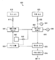
도 6은 가스 소스(610), 액체 소스(620), 프로그램 논리 제어기(PLC) 모듈(630), 질량 유동 제어기(640) 및 멤브레인 접촉기(660)를 포함하는 DI수 기화 시스템(600)의 일 실시예의 개략도를 도시하고 있다. 시스템(600) 내의 압력은 압력 조절기(694, 696) 및 밸브(602)를 통해 조절될 수 있다. 압력 조절기(696)는 감소된 압력을 제공할 수 있는 진공 소스 또는 장치에 접속될 수 있다. 접촉기(660)는 전술된 바와 같은 멤브레인 기반 접촉기일 수 있다. 특정 예로서, 가스 소스(610)는 이산화탄소를 공급할 수 있고, 액체 소스(620)는 물을 공급할 수 있다. 이 예에서, 물과 이산화탄소는 일 실시예에서 엔테그리스 인크로부터 입수 가능한 pHasor![]()
![]()
몇몇 실시예에서, 프로그램 논리 제어기 모듈 또는 하나 이상의 다른 적합한 제어기가 전도도 센서로부터 출력 신호를 수신할 수 있고, 설정점 양의 가스를 액체에 전달하기 위해 가스 질량 유동 제어기(MFC)에 출력 신호를 제공할 수 있다. 몇몇 실시예에서, 큰 유량 변화가 검출될 때 또는 액체 유동 변화 이전의 시간에[피드 포워드(feed forward) 또는 능동 제어], 프로그램 논리 제어기 모듈 또는 하나 이상의 다른 적합한 제어기는 멤브레인 접촉기 내의 가스의 부분 압력을 변화하기 위해 그리고 설정점의 ±20 퍼센트 미만으로 액체 내의 가스의 양의 편차를 유지하기 위해 가스 부분 압력을 제어하는 하나 이상의 장치에 하나 이상의 신호를 송신할 수 있다. 도 6에서, 점선은 예시적인 제어 루프를 표현하고 있다. 예를 들어, 전도도 센서(672)는 액체 내의 가스의 양을 측정하고 PLC 모듈(630)에 대응 신호를 송신할 수 있다. PLC 모듈(630)은 전도도 센서(672)로부터 센서 신호를 분석하고 적절한 조정량이 특정 레벨의 전도도를 유지하기 위해 필요하다고 판정할 수 있다. PLC 모듈(630)은 접촉기 내의 이산화탄소 가스의 부분 압력 및/또는 유동을 조정하기 위해 하나 이상의 조정 신호를 생성하여 질량 유동 제어기(640), 압력 조절기(696) 등에 송신할 수 있다.In some embodiments, a program logic controller module or one or more other suitable controllers may receive an output signal from a conductivity sensor and provide an output signal to a gas mass flow controller (MFC) to deliver a set point amount of gas to the liquid. can do. In some embodiments, when a large flow rate change is detected or at a time prior to the liquid flow change (feed forward or active control), the program logic controller module or one or more other suitable controllers may provide a partial pressure of gas in the membrane contactor. One or more signals may be sent to one or more devices that control the gas partial pressure to change the pressure and maintain the deviation of the amount of gas in the liquid to less than ± 20 percent of the set point. In FIG. 6, the dotted line represents an exemplary control loop. For example, the
큰 액체 유량 변화는, 액체 유량 변화가 액체 내의 가스의 설정점 양의 약 15% 이상 초과, 몇몇 경우에 50% 이상의 초기 편차를 생성하는 것들이고, 몇몇 경우에 큰 액체 유량 변화는 정상 상태 유량의 10 퍼센트 초과이다. 큰 액체 유량 변화 및 전도도에 대한 그 대응 효과의 예가 도 7a에 도시되어 있다. 도 7a에 도시되어 있는 바와 같이, 액체 조성물에 대해 센서에 의해 측정된 바와 같은 액체 내의 가스의 양의 안정도는 약 ±2 퍼센트 이하(0 내지 75초)이고, 여기서 액체인 물 내로 전달되거나 용해된 가스의 비한정적인 설정점 농도는 6.2 마이크로지멘스이다. 이 예에서, 10 lpm 내지 20 lpm의 초기 액체 유량을 2배로 함으로써 생성된 큰 액체 유량 변화 - 접촉기 내의 가스의 부분 압력을 변화시키기 위한 PID 폐루프 제어와 신호의 조합이 없는 - 는 액체 내의 가스의 설정점 양으로부터 대략 50% 편차를 생성할 수 있다. 도 7a에 도시되어 있는 예는 이하에 더 설명된다.Large liquid flow changes are those in which the liquid flow rate changes produce an initial deviation of at least about 15% or more, and in some cases at least 50%, of the set point amount of gas in the liquid, and in some cases the large liquid flow rate changes are Greater than 10 percent. An example of its corresponding effect on large liquid flow rate variations and conductivity is shown in FIG. 7A. As shown in FIG. 7A, the stability of the amount of gas in the liquid as measured by the sensor for the liquid composition is about ± 2 percent or less (0 to 75 seconds), where it is delivered or dissolved into the liquid water. The non-limiting set point concentration of the gas is 6.2 microsiemens. In this example, a large liquid flow rate change created by doubling the initial liquid flow rate of 10 lpm to 20 lpm, without a combination of signal and PID closed loop control to change the partial pressure of the gas in the contactor, Approximately 50% deviation can be generated from the set point amount. The example shown in FIG. 7A is further described below.
본 명세서에 개시된 실시예에서, 액체 내의 용해된 가스 농도의 낮은 편차는 몇몇 실시예에서 약 ±15 퍼센트 이하, 몇몇 실시예에서 약 ±5 퍼센트 이하, 몇몇 실시예에서 약 ±3 퍼센트 이하의 액체 내의 가스의 농도의 안정도를 칭할 수 있다. 몇몇 실시예에서, 액체 내의 가스의 양의 편차는 접촉기의 가스 출구에 감소된 압력의 가스를 제공함으로써 감소될 수 있다. 몇몇 실시예에서, 액체 내의 가스의 양은 액체 유량 변화에 앞서 또는 큰 유량 변화가 검출될 때 접촉기 내의 가스의 부분 압력을 변화시키기 위해 PID 폐루프 제어 및/또는 신호를 이용하여(피드 포워드 또는 능동 제어), 큰 액체 유량 변화에 대한 설정점 내의 원하는 범위 또는 공차에서 유지될 수 있다. 특정 예로서, 도 7b는 10 lpm 내지 20 lpm의 큰 액체 유량 변화를 도시하고 있다. 이 큰 액체 유량 변화에 응답하여, 접촉기 내의 가스의 부분 압력을 변화시키는 신호는, 가스 부분 압력을 제어하는 하나 이상의 장치에 프로그램 논리 제어기 모듈 또는 하나 이상의 다른 적합한 제어기에 의해 송신될 수 있다. 이 예에서, 액체 내의 가스의 양의 편차는 설정점의 ±20 퍼센트 미만으로 유지될 수 있다. 도 7b에 도시되어 있는 예가 이하에 더 설명된다.In the embodiments disclosed herein, the low deviation of dissolved gas concentration in the liquid is within about ± 15 percent in some embodiments, about ± 5 percent or less in some embodiments, and about ± 3 percent or less in liquid in some embodiments. The stability of the concentration of the gas can be referred to. In some embodiments, the variation in the amount of gas in the liquid can be reduced by providing a reduced pressure gas to the gas outlet of the contactor. In some embodiments, the amount of gas in the liquid is controlled by using PID closed loop control and / or signals (feed forward or active control) to change the partial pressure of the gas in the contactor prior to the liquid flow rate change or when a large flow rate change is detected. Can be maintained at a desired range or tolerance within the set point for large liquid flow rate variations. As a specific example, FIG. 7B shows a large liquid flow rate change of 10 lpm to 20 lpm. In response to this large liquid flow rate change, a signal that changes the partial pressure of the gas in the contactor may be sent by a program logic controller module or one or more other suitable controller to one or more devices that control the gas partial pressure. In this example, the variation in the amount of gas in the liquid can be maintained at less than ± 20 percent of the set point. The example shown in FIG. 7B is further described below.
도 7c는 전술된 바와 같이 접촉기의 가스 출구에 감소된 압력의 가스를 제공함으로써, 액체 내의 가스의 양의 편차가 정상 상태 액체 조성물 유량의 약 10% 또는 약 lpm의 액체 유량 변화에 대한 설정점의 약 ±12 퍼센트 이하로 감소될 수 있다는 것을 도시하고 있다. 도 7b에 도시되어 있는 예가 이하에 더 설명된다. 도 7b 및 도 7c의 결과는, PID 제어 및 선택적으로 가스 부분 압력을 제어하기 위한 신호를 사용하여, 본 명세서에 개시된 몇몇 실시예가 액체 유량 변화를 구성하고 약 30초 이내에서 20% 미만으로 액체에 전달되는 가스의 양의 편차를 유지할 수 있다는 것을 도시하고 있다. 편차가 적을수록 특정 제조 프로세스에 특히 유용할 수 있는 더 큰 안정도를 제공할 수 있다. 액체 내의 용해된 가스 농도의 낮은 편차로부터 이득을 얻을 수 있는 예시적인 제조 프로세스는, 이에 한정되는 것은 아니지만 반도체 웨이퍼 세척을 포함할 수 있다.FIG. 7C shows that by providing a reduced pressure gas to the gas outlet of the contactor as described above, the variation in the amount of gas in the liquid is at a set point for a liquid flow rate change of about 10% or about lpm of steady state liquid composition flow rate. It can be reduced to about ± 12 percent or less. The example shown in FIG. 7B is further described below. The results of FIGS. 7B and 7C show that, using PID control and optionally a signal to control the gas partial pressure, some embodiments disclosed herein constitute a liquid flow rate change and less than 20% in liquid within about 30 seconds. It is shown that the variation in the amount of gas delivered can be maintained. Smaller deviations can provide greater stability that can be particularly useful for certain manufacturing processes. Exemplary fabrication processes that may benefit from low variations in dissolved gas concentration in a liquid may include, but are not limited to, semiconductor wafer cleaning.
본 명세서에 개시된 실시예는 감소된 압력에서 가스의 낮은 부분 압력을 생성하고 액체 내에 이 가스 조성물을 전달할 수 있다. 이는 본 명세서에 개시된 실시예에서 액체 내의 가스의 양이 감소되지 않기 때문에 가스 스트리핑(stripping) 및 진공 탈가스의 조합에 의한 액체의 탈가스 처리와는 상이하다. 오히려, 몇몇 실시예에서, 액체 내의 가스의 양 또는 총량이 증가된다. 본 명세서에 개시된 실시예는 감소된 압력에서 멤브레인 접촉기의 다공성 요소의 가스 접촉측으로 낮은 부분 압력의 가스를 제공한다. 본 명세서에 개시된 실시예를 구현하는 멤브레인 접촉기에 의해 처리된 액체는, 멤브레인 접촉기로 입력된 액체 공급에서의 초기의 가스의 양과 비교하여 액체 내에 더 많은 가스를 가질 것이다. 전통적인 가스 접촉 장치에서, 높은 부분 압력의 가스가 액체와 접촉한다. 높은 부분 압력의 예는 101 kPa 이상을 포함한다. 본 명세서에 개시된 실시예에서, 낮은 부분 압력의 가스가 액체와 접촉한다. 낮은 부분 압력의 예는 약 40 kPa 이하를 포함한다.Embodiments disclosed herein can produce a low partial pressure of gas at reduced pressure and deliver this gas composition into a liquid. This is different from the degassing of the liquid by a combination of gas stripping and vacuum degassing since the amount of gas in the liquid is not reduced in the embodiments disclosed herein. Rather, in some embodiments, the amount or total amount of gas in the liquid is increased. Embodiments disclosed herein provide a low partial pressure of gas to the gas contacting side of the porous element of the membrane contactor at reduced pressure. The liquid treated by the membrane contactor implementing the embodiments disclosed herein will have more gas in the liquid compared to the amount of initial gas in the liquid supply input to the membrane contactor. In conventional gas contacting devices, high partial pressure gas is in contact with the liquid. Examples of high partial pressures include 101 kPa or more. In the embodiments disclosed herein, low partial pressure gas is in contact with the liquid. Examples of low partial pressures include about 40 kPa or less.
본 명세서에 개시된 실시예에서, 액체 내의 낮은 레벨의 가스 또는 액체 내의 가스의 희석 용액은 접촉기에 의해 액체 내에 전달된 가스의 양을 칭한다. 액체 내의 가스의 양은 실시예마다 변할 수 있다. 몇몇 실시예에서, 액체 내의 가스의 양은 5000 ppm 이하일 수 있다. 몇몇 실시예에서, 액체 내의 가스의 양은 500 ppm 이하일 수 있다. 몇몇 실시예에서, 액체 내의 가스의 양은 50 ppm 이하일 수 있다. 몇몇 실시예에서, 액체 내의 가스의 양은 5 ppm 이하일 수 있다.In the embodiments disclosed herein, the low level gas in the liquid or the dilute solution of the gas in the liquid refers to the amount of gas delivered into the liquid by the contactor. The amount of gas in the liquid may vary from embodiment to embodiment. In some embodiments, the amount of gas in the liquid can be up to 5000 ppm. In some embodiments, the amount of gas in the liquid can be 500 ppm or less. In some embodiments, the amount of gas in the liquid can be 50 ppm or less. In some embodiments, the amount of gas in the liquid can be 5 ppm or less.
몇몇 실시예에서, 액체 내의 가스의 양은 액체의 전도도에 의해 측정될 수 있다. 몇몇 실시예에서, 용액(액체 및 용해되거나 반응된 가스)의 전도도는 5 마이크로지멘스(μS) 이하일 수 있다. 몇몇 실시예에서, 용액의 전도도는 2 μS 이하일 수 있다. 당 기술 분야의 숙련자들에 의해 이해될 수 있는 바와 같이, 분당 2 리터 내지 분당 20 리터의 액체 유량에서 액체 내의 더 낮은 레벨의 가스가 15% 미만의 농도 편차를 갖도록 제조하는 것은 어려울 수 있다.In some embodiments, the amount of gas in the liquid can be measured by the conductivity of the liquid. In some embodiments, the conductivity of the solution (liquid and dissolved or reacted gas) may be 5 microsiemens (μS) or less. In some embodiments, the conductivity of the solution may be 2 μS or less. As will be appreciated by those skilled in the art, it can be difficult to produce lower levels of gas in a liquid having a concentration deviation of less than 15% at a liquid flow rate of 2 liters per minute to 20 liters per minute.
본 명세서에 개시된 실시예에서, 접촉기의 가스 접촉 표면에서 감소된 압력을 갖는 접촉기에 의해 액체 내로 전달된 가스는 기포 또는 미세기포가 없거나 실질적으로 없다. 몇몇 실시예에서, 액체 내에 접촉기에 의해 형성될 수 있는 임의의 기포 또는 미세기포는 접촉기의 액체 출구의 하류측의 선택적 필터에 의해 제거될 수 있다. 기포 또는 미세기포는 본 명세서에 참조로서 포함되어 있는 국제 특허 출원 공개 WO2005/072487 및 WO2006/007376에 설명된 바와 같이 광학 입자 카운터를 사용하여 검출될 수 있다. 예를 들어, 단지 입자만이 액체 내에 존재할 때, 누적된 입자 카운트 데이터는 로그-로그 축 상에 플롯팅될 때 -2 내지 -3.5의 기울기를 갖는 선형 곡선을 형성할 수 있다. 심한 굴곡부(knee) 또는 -2 미만의 낮은 기울기를 나타내는 입자 카운트 데이터는 미세기포의 존재를 나타낸다.In the embodiments disclosed herein, the gas delivered into the liquid by the contactor having a reduced pressure at the gas contacting surface of the contactor is free or substantially free of bubbles or microbubbles. In some embodiments, any bubbles or microbubbles that may be formed by the contactor in the liquid may be removed by a selective filter downstream of the liquid outlet of the contactor. Bubbles or microbubbles can be detected using an optical particle counter as described in International Patent Application Publications WO2005 / 072487 and WO2006 / 007376, incorporated herein by reference. For example, when only particles are present in the liquid, the accumulated particle count data can form a linear curve with a slope of -2 to -3.5 when plotted on the log-log axis. Particle count data showing severe knees or low slopes below -2 indicate the presence of microbubbles.
본 명세서에 개시된 실시예에서, 액체 내의 가스의 농도는 접촉기 내에 공급 액체 유동과의 용해, 반응 또는 이들의 조합에 의해 공급 액체 내로 전달되는 임의의 가스를 칭한다. 예를 들어, CO2 및 HCl과 같은 가스는 물과 같은 액체와 반응하여 이온을 형성하는 반면에 N2와 같은 가스는 물과 같은 액체와 반응하지 않는다. 가스와 액체 사이의 반응에 의해 형성된 반응 생성물의 농도는 액체 내의 용해된 가스의 농도의 척도로서 측정되고 사용될 수 있다. 비한정적인 예는 CO2 또는 NH3 또는 HCl 가스 등의 비저항 또는 pH를 포함할 수 있다. 액체와 반응하지 않는 가스에 대해, 액체 내의 용해된 가스의 농도는 다양한 기술을 이용하여 측정될 수 있다. 적합한 예시적인 기술은, 이들에 한정되는 것은 아니지만 분광, 전자화학 및 크로마토그래피 기법을 포함한다. 액체와 반응하지 않는 예시적인 가스는, 이들에 한정되는 것은 아니지만 O3, O2, N2 등을 포함할 수 있다. 본 명세서에 개시된 실시예는 사용된 가스의 유형에 의해 한정되는 것은 아니라는 것을 주목하라. 유용한 가스는, 이들에 한정되는 것은 아니지만 HF, CO2, O3, O2, N2, Ar 등뿐만 아니라 아세트산, NH3, HCl 등과 같은 액체 및 고체 소스의 증기로부터 유도된 가스와 같이 반도체 처리에 이용되는 것들을 포함한다. 이들 가스와 다른 가스 중 하나 이상의 조합은 액체 또는 액체 조성물 내에 용해될 수 있는 가스 조성물을 제조하는 데 사용될 수 있다. 이들 가스의 임의의 것은 단독으로 사용될 수 있다.In the embodiments disclosed herein, the concentration of gas in the liquid refers to any gas delivered into the feed liquid by dissolution, reaction, or a combination thereof with the feed liquid flow in the contactor. For example, gases such as CO 2 and HCl react with liquids such as water to form ions, while gases such as N 2 do not react with liquids such as water. The concentration of the reaction product formed by the reaction between the gas and the liquid can be measured and used as a measure of the concentration of dissolved gas in the liquid. Non-limiting examples may include specific resistance or pH, such as CO 2 or NH 3 or HCl gas. For gases that do not react with the liquid, the concentration of dissolved gas in the liquid can be measured using various techniques. Suitable exemplary techniques include, but are not limited to, spectroscopic, electrochemical and chromatographic techniques. Exemplary gases that do not react with the liquid may include, but are not limited to, O 3 , O 2 , N 2 , and the like. Note that the embodiments disclosed herein are not limited by the type of gas used. Useful gases include, but are not limited to, semiconductor processing, such as gases derived from vapors of liquid and solid sources such as acetic acid, NH 3 , HCl, as well as HF, CO 2 , O 3 , O 2 , N 2 , Ar, and the like. Includes those used for Combinations of one or more of these gases with other gases may be used to prepare a gas composition that can be dissolved in a liquid or liquid composition. Any of these gases may be used alone.
몇몇 실시예에서, 접촉기의 가스 입구에 전달되거나 제공된 가스는 접촉기 내의 액체의 압력보다 낮은 압력에 있을 수 있다. 이 압력차의 결과로서, 가스는 액체 내의 기포의 형성 없이 액체 내로 전달될 수 있다. 가스의 입구 압력은 임의의 선택된 액체 유량에 대해 액체 내의 가스의 타겟 농도를 형성하도록 선택될 수 있다. 접촉기에 접속된 가스 유동 제어기의 입구에 제공된 가스는 몇몇 실시예에서 40 psi(275.8 kPa) 이하, 몇몇 실시예에서 15 psi(103.4 kPa) 이하, 몇몇 실시예에서 2 psi(13.8 kPa) 이하일 수 있다. 접촉기로의 낮은 가스 압력 입구는 가스 유동에서 스파이크(spike)를 최소화할 수 있고, 낮은 부분 압력 공급 가스를 준비하는 것을 지원할 수 있다. 가스의 유량은 액체 내로의 가스 전달이 요구되지 않을 때 0일 수 있고, 가스 유량은 가스 접촉에 대해 0보다 클 수 있고, 접촉기(들)의 크기, 가스, 액체 내의 가스의 용해도, 액체의 온도, 액체 내로 전달되는 가스의 원하는 양, 접촉기의 가스 입구에 전달되거나 제공된 가스의 감소된 압력 또는 이들의 조합을 포함하는 복수의 인자에 기초하여 선택될 수 있다. 가스 질량 유량계 또는 제어기에 의해 측정된 가스 유동은 몇몇 실시예에서 1000 sccm 미만일 수 있다. 가스 유동은 몇몇 실시예에서 0 sccm 초과 내지 100 sccm(표준 입방 센티미터) 이하, 몇몇 실시예에서 0 sccm 초과 내지 10 sccm 이하의 범위일 수 있다.In some embodiments, the gas delivered or provided to the gas inlet of the contactor may be at a pressure lower than the pressure of the liquid in the contactor. As a result of this pressure difference, the gas can be delivered into the liquid without the formation of bubbles in the liquid. The inlet pressure of the gas can be selected to form a target concentration of gas in the liquid for any selected liquid flow rate. The gas provided at the inlet of the gas flow controller connected to the contactor may be up to 40 psi (275.8 kPa) in some embodiments, up to 15 psi (103.4 kPa) in some embodiments, up to 2 psi (13.8 kPa) in some embodiments. . The low gas pressure inlet to the contactor can minimize spikes in the gas flow and can assist in preparing a low partial pressure feed gas. The flow rate of the gas may be zero when no gas delivery into the liquid is required, the gas flow rate may be greater than zero for gas contact, the size of the contactor (s), the solubility of the gas in the gas, the liquid, the temperature of the liquid And a plurality of factors including the desired amount of gas delivered into the liquid, the reduced pressure of the gas delivered or provided to the gas inlet of the contactor, or a combination thereof. The gas flow measured by a gas mass flow meter or controller may be less than 1000 sccm in some embodiments. Gas flows may range from greater than 0 sccm to less than 100 sccm (standard cubic centimeters) in some embodiments, and greater than 0 sccm to less than 10 sccm in some embodiments.
가스 및 액체는 접촉기 내에서 역류 유동할 수 있다. 다공성 멤브레인을 이용하는 접촉기에 대해, 가스는 멤브레인의 각 측에 있을 수 있고, 중공 섬유 다공성 멤브레인 접촉기에 대해 가스는 몇몇 실시예에서 멤브레인의 쉘측에 있을 수 있다.Gases and liquids may flow countercurrently within the contactor. For contactors using porous membranes, the gas may be on each side of the membrane, and for hollow fiber porous membrane contactors, the gas may be on the shell side of the membrane in some embodiments.
본 명세서에 개시된 실시예에 의해 준비된 액체 조성물 내의 총 가스뿐만 아니라 사용된 공급 액체는 다수의 방식으로 측정될 수 있다. 일례는 엠, 마이어(M. Meyer)의 Pfluegers Archive European Journal of Physiology, pp. 161-165, vol. 375, 7월(1978년)에 의해 설명된 방법을 사용하는 가스 크로마토그래피이다. 동결 펌프 해동 사이클이 또한 가스 농도를 측정하기 위해 적합한 건조제 또는 증기 흡수제와 함께 사용될 수 있다.The feed gas used as well as the total gas in the liquid composition prepared by the embodiments disclosed herein can be measured in a number of ways. One example is M. Meyer, Pfluegers Archive European Journal of Physiology, pp. 161-165, vol. 375, gas chromatography using the method described by July (1978). Freeze pump thawing cycles may also be used with suitable desiccants or vapor absorbers to measure gas concentration.
몇몇 용례에서, 액체 조성물 내에서 가스가 요구에 따라 다양한 유량에서 액체 내의 가스의 일정한 양 또는 설정점을 갖도록 하는 것이 유리할 수 있다. 예를 들어, 본 명세서에 개시된 실시예를 구현하는 장치는, 물 내에 용해된 가스의 양을 포함하는 동일한 세척 조성물을 하나 이상의 단일 웨이퍼 세척 도구에 제공할 수 있다. 이 세척 액체 조성물을 위한 각각의 세척 도구로부터의 요구에 따라, 장치로부터의 유량 요건 또는 요구가 다양할 수 있다. 증가된 또는 감소된 요구에 기인하는 액체 조성물의 유량 변화가 예를 들어 장치 정상 상태 유동의 약 10% 이하로 작은 몇몇 경우에, 액체(액체 조성물) 내의 가스의 양은 이들 작은 유량 변화에 대해 PID 또는 퍼지 논리 제어만에 의한 액체 내의 가스의 설정점 양의 ±20% 이하, 몇몇 경우에 ±12% 이하로 유지될 수 있다. 액체 조성물에 대한 유량 변화가 장치로부터의 증가된 또는 감소된 요구에 기인하여 큰 경우에, 예를 들어 유동이 정상 상태에서 장치 작동으로부터 2배가 되거나 절반이 된 몇몇 경우에, 접촉기 내의 가스의 부분 압력을 변화시키는 신호와 PID 또는 퍼지 논리의 조합은 액체 내의 가스의 설정점 양의 ±20% 이하 이내로 액체 내의 가스의 양을 유지하는 데 사용될 수 있다. 이 신호는, 이들에 한정되는 것은 아니지만, 접촉기 내로의 가스의 유량을 증가시킴으로써 접촉기 내의 가스의 부분 압력을 변경시키고, 접촉기에 접속된 압력 조절기 또는 진공 소스를 조정함으로써 시스템의 압력을 변경시키고, 접촉기로부터 첨가되거나 제거된 희석 가스의 양을 변경시키고, 이들 중 임의의 하나 이상을 포함하는 조합을 변경시키는 것을 초래할 수 있다. 접촉기 내의 가스의 부분 압력을 변화시키는 신호는, 예를 들어 액체 조성물 유량을 모니터링하는 제어기에 의해 검출된 문턱값 유량 변화에 기초하여 장치 내의 제어기에 의해 생성될 수 있다. 몇몇 경우에, 접촉기 내의 가스의 부분 압력을 변화시키는 신호는 장치에 접속된 하나 이상의 도구로부터 입력에 의해 생성되는데, 이 도구는 능동, 개방 루프 또는 피드 포워드 제어를 포함할 수 있다. 접촉기 내의 가스의 부분 압력을 변화시키는 신호는 몇몇 경우에 장치에 접속된 도구 또는 장치로부터의 능동 제어 또는 피드 포워드 제어에 의한 예측된 액체 조성물 유량 변화 전에 소정 시간 간격에서 시작될 수 있다. 이러한 시간 간격은 시스템 유지 체적 및 접촉기 시간 상수, 시스템의 체류 시간 등에 따를 수 있다.In some applications, it may be advantageous to have the gas in the liquid composition have a constant amount or set point of gas in the liquid at various flow rates as desired. For example, an apparatus embodying an embodiment disclosed herein can provide one or more single wafer cleaning tools with the same cleaning composition comprising the amount of gas dissolved in water. Depending on the needs from each cleaning tool for this cleaning liquid composition, the flow rate requirements or requirements from the device may vary. In some cases where the change in the flow rate of the liquid composition due to increased or decreased demand is small, for example less than about 10% of the device steady state flow, the amount of gas in the liquid (liquid composition) is either PID or It can be maintained at ± 20% or less, and in some cases ± 12% or less of the set point amount of gas in the liquid by purge logic control alone. If the flow rate change for the liquid composition is large due to increased or decreased demand from the device, for example in some cases where the flow doubled or halved from the device operation in steady state, the partial pressure of the gas in the contactor The combination of a signal and a PID or purge logic to change the voltage can be used to keep the amount of gas in the liquid within ± 20% of the set point amount of the gas in the liquid. These signals include, but are not limited to, changing the partial pressure of the gas in the contactor by increasing the flow rate of gas into the contactor, changing the pressure of the system by adjusting a pressure regulator or vacuum source connected to the contactor, Altering the amount of diluent gas added or removed therefrom, and resulting in altering the combination comprising any one or more of these. The signal that changes the partial pressure of the gas in the contactor can be generated by a controller in the apparatus based on, for example, the threshold flow rate change detected by the controller monitoring the liquid composition flow rate. In some cases, a signal that changes the partial pressure of the gas in the contactor is generated by input from one or more instruments connected to the device, which may include active, open loop, or feed forward control. The signal that changes the partial pressure of the gas in the contactor may in some cases start at a predetermined time interval before the expected liquid composition flow rate change by active control or feed forward control from a tool or device connected to the device. This time interval may depend on the system holding volume and contactor time constants, the residence time of the system, and the like.
가스 부분 압력은 설정점 농도를 생성하고 액체 내로 전달된 가스의 양의 편차를 최소화하기 위해 계산, 레시피(recipe) 또는 룩업 테이블(lookup-table)에 기초하여 수정될 수 있다. 가스 압력의 예는, 이들에 한정되는 것은 아니지만, 가스 시스템 압력, 희석 가스 부분 압력, 가스 질량 유량 또는 이들의 조합을 포함할 수 있다. 장치의 몇몇 실시예는 매 60초 이내에서 발생하는 액체 조성물의 유량의 단계적인 변화를 위한 설정점 값의 ±20% 이하로 액체 조성물에 대해 액체 내의 가스의 양을 유지할 수 있다. 장치의 몇몇 실시예는 매 30초 이내에서 발생하는 액체 조성물의 유동의 단계적인 변화에 대한 설정점 값의 ±20% 이하로 액체 조성물에 대해 액체 내의 가스의 양을 유지할 수 있다.The gas partial pressure may be modified based on calculations, recipes, or lookup-tables to produce set point concentrations and minimize variations in the amount of gas delivered into the liquid. Examples of gas pressures may include, but are not limited to, gas system pressures, diluent gas partial pressures, gas mass flow rates, or combinations thereof. Some embodiments of the device may maintain the amount of gas in the liquid for the liquid composition at no more than ± 20% of the set point value for the stepwise change in flow rate of the liquid composition occurring within every 60 seconds. Some embodiments of the device may maintain the amount of gas in the liquid for the liquid composition at no more than ± 20% of the set point value for the stepwise change in flow of the liquid composition occurring within every 30 seconds.
이 개시내용 내에서, 구성 요소는 멤브레인 접촉기의 다공성 요소의 가스 접촉측의 압력 또는 감소된 압력이 몇몇 실시예에서 40 kPa(-18 inHg), 몇몇 실시예에서 12 kPa(-26 inHg) 이하, 몇몇 실시예에서 6 kPa(-28 inHg)일 수 있도록 선택된다. 다공성 요소의 가스 접촉측의 압력은 접촉기의 가스 출구에서 또는 몇몇 경우에 하우징 내의 압력 게이지에 의해 측정될 수 있다. 접촉기의 가스 접촉측에서의 압력은 접촉기 내에 총 가스 압력을 유지하기 위해 제어기에 의해 수동적으로 또는 자동으로 조정될 수 있다. 몇몇 실시예에서, 접촉기의 가스 출구에서 측정된 접촉기 내의 압력은 압력 제어기에 의해 제어될 수 있다. 선택적으로, 몇몇 실시예에서, 통기성 응축물 트랩이 접촉기 가스 출구와 감소된 압력 장치 또는 소스 사이에서 유체 연통하여 배치될 수 있다. 몇몇 실시예에서, 접촉기의 가스 출구와 감소된 압력의 소스 사이의 유체 경로의 전도성은 응축물이 접촉기로부터 제거되도록 선택된다. 몇몇 실시예에서, 감소된 압력의 소스는 접촉기로부터 액체 응축물을 제거하기에 충분한 펌프 속도를 가질 수 있다.Within this disclosure, the component has a pressure or reduced pressure at the gas contacting side of the porous element of the membrane contactor in some embodiments up to 40 kPa (-18 inHg), in some embodiments up to 12 kPa (-26 inHg), In some embodiments it is selected to be 6 kPa (-28 inHg). The pressure at the gas contacting side of the porous element can be measured at the gas outlet of the contactor or in some cases by a pressure gauge in the housing. The pressure at the gas contacting side of the contactor can be adjusted manually or automatically by the controller to maintain the total gas pressure in the contactor. In some embodiments, the pressure in the contactor measured at the gas outlet of the contactor may be controlled by a pressure controller. Optionally, in some embodiments, a breathable condensate trap may be placed in fluid communication between the contactor gas outlet and the reduced pressure device or source. In some embodiments, the conductivity of the fluid path between the gas outlet of the contactor and the source of reduced pressure is selected such that condensate is removed from the contactor. In some embodiments, the source of reduced pressure may have a pump speed sufficient to remove liquid condensate from the contactor.
이 개시내용 내에서, 감소된 압력의 소스는 접촉기의 다공성 요소와 유체로 연통되고 접촉기 내의 압력을 감소시킬 수 있는 장치를 칭한다. 감소된 압력의 적합한 소스는, 이들에 한정되는 것은 아니지만, 진공 펌프, 벤츄리관, 가정용 진공과 같은 진공 또는 감소된 압력의 소스 등을 포함할 수 있다. 감소된 압력의 장치 또는 소스는, 예를 들어 이들에 한정되는 것은 아니지만 접촉기의 가스 출구, 가스 출구에 접속된 도관 등과 같은 임의의 지점에서 접촉기에 유체로 연통될 수 있다. 감소된 압력의 장치 또는 소스는 감소된 압력의 소스로의 접속 또는 장치의 작동의 결과로서 접촉기의 다공성 요소에서 감소된 압력 또는 낮은 압력을 제공한다. 장치의 작동시에 감소된 압력의 장치 또는 소스에 접속된 접촉기의 다공성 요소에서의 압력은, 접촉기를 통한 가스만의 유동으로부터의 압력 손실에 기인하여 접촉기의 가스 입구에서 가스의 압력보다 작고 접촉기의 가스 출구에서의 압력보다 작다. 장치 내의 감소된 압력은 낮은 부분 압력 및 낮은 절대 압력에서 가스 조성물을 다공성 요소에 제공한다. 접촉기의 작동 중에 다공성 요소에서의 감소된 압력은 실질적으로 접촉기로의 가스 입구의 압력과 접촉기로부터의 액체의 증발에 기인하는 압력의 합이다. 장치는 액체가 존재하는 소정의 다공성 요소 접촉 영역에 대해 접촉기 내의 가스의 낮은 부분 압력을 성취하기 위해 충분한 펌핑 속도를 갖는 진공 펌프 또는 진공 소스(벤츄리관)를 갖도록 구성되거나 형성될 수 있다.Within this disclosure, a source of reduced pressure refers to a device in fluid communication with the porous element of the contactor and capable of reducing the pressure in the contactor. Suitable sources of reduced pressure may include, but are not limited to, vacuum pumps, venturi tubes, vacuum or reduced pressure sources such as home vacuums, and the like. The reduced pressure device or source may be in fluid communication with the contactor at any point, such as but not limited to, the gas outlet of the contactor, conduits connected to the gas outlet, and the like. The reduced pressure device or source provides a reduced or lower pressure at the porous element of the contactor as a result of connection to the source of reduced pressure or operation of the device. The pressure at the porous element of the contactor connected to the device or source of reduced pressure upon operation of the device is less than the pressure of the gas at the gas inlet of the contactor due to the pressure loss from the flow of gas only through the contactor. Less than the pressure at the gas outlet. The reduced pressure in the device provides the gas composition to the porous element at low partial pressure and low absolute pressure. The reduced pressure in the porous element during operation of the contactor is substantially the sum of the pressure at the gas inlet to the contactor and the pressure due to the evaporation of the liquid from the contactor. The apparatus may be configured or formed to have a vacuum pump or vacuum source (venturi tube) with a pumping speed sufficient to achieve a low partial pressure of gas in the contactor for any porous element contacting region in which liquid is present.
이 개시내용 내에서, 액체는 하나 이상의 가스가 접촉기의 다공성 요소를 가로질러 전달되는 하나 이상의 액체(혼합물 또는 용액)를 칭한다. 액체는 예를 들어 초순수 물(UPW), 탈이온화수(DIW)와 같이 실질적으로 순수할 수 있거나, 또는 액체는 하나 이상의 액체의 혼합물 또는 액체 조성물일 수 있다. 액체 조성물의 비한정적인 예는 물 및 이소프로필 알코올을 포함할 수 있다. 몇몇 경우에, 액체 또는 액체 조성물은 물과 같은 액체 내의 고체 또는 겔 재료의 현탁액을 포함할 수 있다. 이러한 재료의 비한정적인 예는 CMP 슬러리일 수 있다. 액체는 탈가스될 수 있고 가스와 접촉되기 전에 1 ppm 미만의 총 용해 가스를 갖는다.Within this disclosure, liquid refers to one or more liquids (mixtures or solutions) in which one or more gases are delivered across the porous element of the contactor. The liquid may be substantially pure, for example ultrapure water (UPW), deionized water (DIW), or the liquid may be a mixture or liquid composition of one or more liquids. Non-limiting examples of liquid compositions can include water and isopropyl alcohol. In some cases, the liquid or liquid composition may comprise a suspension of solid or gel material in a liquid, such as water. Non-limiting examples of such materials may be CMP slurries. The liquid can be degassed and has a total dissolved gas of less than 1 ppm before being contacted with the gas.
접촉기의 크기 및/또는 접촉기의 수에 따라, 특정 용례에 대해 액체 내로 전달된(용해된 또는 액체와 반응하는) 가스의 농도를 성취하기 위한 접촉기를 통과하는 액체 유량은 다양하고 그리고/또는 개산(scale)될 수 있다. 분당 약 20 리터까지 유동하는, 미국 미네소타주 차스카 소재의 엔테그리스 인크로부터 입수 가능한, pHasor![]()
![]()
본 명세서에 개시된 실시예에서, 적합한 접촉기는 가스로부터 액체를 분리하고 요소 내의 하나 이상의 기공을 통해 액체 내로의 가스의 전달 또는 접촉을 허용하는 다공성 요소 또는 다공성 멤브레인을 포함할 수 있다. 다공성 요소는 하우징 내에 배치되고 가스 유동과 액체 유동을 분리할 수 있다. 몇몇 실시예에서, 다공성 요소는 약 5 내지 1000 미크론 두께의 얇은 다공성 멤브레인을 포함할 수 있다. 몇몇 실시예에서, 다공성 요소는 소결된 입자를 포함할 수 있고, 0.5 센티미터 이하의 두께를 가질 수 있다. 몇몇 실시예에서, 직렬 또는 병렬 또는 이들의 조합으로 배열된 하나 이상의 접촉기가 사용될 수 있다. 적합한 접촉기는 미국 미네소타주 차스카 소재의 엔테그리스 인크로부터의 pHasor![]()
![]()
![]()
![]()
본 명세서에 개시된 실시예에서, 액체 응축물이 감소된 압력 소스에 의해 접촉기 멤브레인 표면으로부터 제거될 수 있고 접촉기의 기계적 및 화학적 안정성이 열화되지 않으면 접촉기 내의 액체 온도는 제한되지 않는다. 선택적으로, 접촉기로부터의 액체 입구 또는 출구의 온도는 열교환기에 의해 상승되거나 저하될 수 있다. 적합한 열교환기는, 이에 한정되는 것은 아니지만 미국 미네소타주 차스카 소재의 엔테그리스 인크로부터 입수 가능한 폴리머 열교환기를 포함할 수 있다. 몇몇 실시예에서, 제어기는 온도 센서 입력 신호에 응답하여, 열교환기에 제어 신호를 송신함으로써 접촉기로부터의 액체 입구 또는 출구의 온도를 상승시키거나 저하시키도록 구성될 수 있다.In the embodiments disclosed herein, the liquid temperature in the contactor is not limited unless liquid condensate can be removed from the contactor membrane surface by a reduced pressure source and the mechanical and chemical stability of the contactor is not degraded. Optionally, the temperature of the liquid inlet or outlet from the contactor can be raised or lowered by the heat exchanger. Suitable heat exchangers may include, but are not limited to, polymer heat exchangers available from Entegris Inc., Chaska Minnesota, USA. In some embodiments, the controller may be configured to raise or lower the temperature of the liquid inlet or outlet from the contactor by sending a control signal to the heat exchanger, in response to the temperature sensor input signal.
몇몇 실시예에서, 시스템 제어기는 시스템 내의 다양한 구성 요소로부터 하나 이상의 입력 신호를 수신하도록 구성될 수 있다. 이러한 신호는 유선, 무선, 광 섬유, 이들의 조합 등을 포함하는 다양한 방식으로 시스템 제어기와 통신할 수 있다. 하나 이상의 입력 신호는, 이들에 한정되는 것은 아니지만, 접촉기 내로의 가스의 유동에 비례하는 신호, 가스 출구 또는 다공성 요소에서 압력에 비례하는 신호, 액체 내로 전달된 가스의 양(농도)에 비례하는 센서로부터의 신호, 또는 접촉기 내로의 액체의 유동에 비례하는 신호를 포함할 수 있다. 제어기는 접촉기 내로의 가스의 유동, 접촉기의 가스 출구에서의 압력, 액체 내의 가스의 농도, 접촉기 내로의 액체의 유동 또는 이들의 임의의 조합을 각각의 것에 대한 설정점 값과 비교할 수 있다. 이들 입력의 각각에 대한 값은, 원하는 설정점 값으로부터의 차이를 계산하거나 룩업 테이블로부터 결정하는 데 사용될 수 있고, 제어기는 설정점 농도의 타겟 범위 또는 공차 이내로 액체 내로 전달된 가스의 양 또는 농도를 유지하기 위해, 접촉기 내로의 가스의 유동을 변경하기 위한 출력 신호, 접촉기의 출구에서의 압력을 변경하기 위한 출력 신호, 접촉기 내로의 액체의 유동을 변경하기 위한 출력 신호 또는 이들의 임의의 조합을 생성할 수 있다. 이러한 출력 신호는 디지털, 전압, 전류 등일 수 있다. 타겟 범위는 몇몇 실시예에서 설정점 농도의 15%, 몇몇 실시예에서 설정점 농도의 5% 이하, 몇몇 실시예에서 설정점 농도의 3% 이하일 수 있다. 설정점 농도의 미리 결정된 범위 이내로 액체 내의 가스의 농도를 유지하기 위해, 제어기는 PID, 퍼지 또는 임의의 적합한 제어 논리를 이용할 수 있다. 몇몇 실시예에서, 하나 이상의 제어기가 사용될 수 있다. 몇몇 실시예는 캐스케이드 제어기를 포함할 수 있다.In some embodiments, the system controller may be configured to receive one or more input signals from various components in the system. Such signals may communicate with the system controller in a variety of ways, including wired, wireless, optical fiber, combinations thereof, and the like. One or more input signals are, but are not limited to, signals proportional to the flow of gas into the contactor, signals proportional to the pressure at the gas outlet or porous element, and sensors proportional to the amount (concentration) of gas delivered into the liquid. Or a signal proportional to the flow of liquid into the contactor. The controller can compare the flow of gas into the contactor, the pressure at the gas outlet of the contactor, the concentration of the gas in the liquid, the flow of the liquid into the contactor, or any combination thereof, with the set point value for each. The value for each of these inputs can be used to calculate the difference from the desired setpoint value or to determine from the lookup table, and the controller can determine the amount or concentration of gas delivered into the liquid within the target range or tolerance of the setpoint concentration. To maintain, generate an output signal for changing the flow of gas into the contactor, an output signal for changing the pressure at the outlet of the contactor, an output signal for changing the flow of liquid into the contactor, or any combination thereof. can do. This output signal may be digital, voltage, current, or the like. The target range may be 15% or less of the setpoint concentration in some embodiments, 5% or less of the setpoint concentration in some embodiments, or 3% or less of the setpoint concentration in some embodiments. To maintain the concentration of the gas in the liquid within a predetermined range of set point concentrations, the controller may use PID, purge or any suitable control logic. In some embodiments, more than one controller may be used. Some embodiments may include a cascade controller.
몇몇 실시예에서는, 농도 센서가 사용되지 않는다. 이들 실시예에서, 액체 내로 전달된 가스의 농도는 액체의 질량 유동, 가스, 접촉기 크기 및 효율뿐만 아니라 시스템 압력 및 온도에 기초하여 결정될 수 있다. 몇몇 실시예에서, 제어기는 PID 또는 퍼지 논리 제어기의 피드백(또는 폐루프) 제어를 피드 포워드(또는 개방 루프) 제어와 조합할 수 있다. 액체 내의 원하는 양의 가스 또는 액체 조성물의 원하는 유량에 대한 외부 도구 입력, 프로세스 레시피의 인지 또는 제조 사이클의 인지가, 제어기에 의해 피드 포워드되어 설정점의 ±20% 이하 이내로 액체 조성물의 편차를 유지하기 위해 PID 출력과 조합될 수 있다. 몇몇 경우에, 접촉기 내의 가스의 부분 압력의 변화를 초래하는 제어기 또는 도구로부터의 피드 포워드 신호가 제어기 출력의 주요 부분을 제공하며, PID, 퍼지, 또는 다른 제어기가 이어서 센서에 의해 결정되는 바와 같이 액체 내의 가스의 양의 실제값과 액체 내의 가스의 설정점 양 사이에 남아 있는 어떠한 차이 또는 오차에도 응답하기 위해 사용될 수 있다.In some embodiments, no concentration sensor is used. In these embodiments, the concentration of gas delivered into the liquid can be determined based on the system pressure and temperature as well as the mass flow, liquid, contactor size and efficiency of the liquid. In some embodiments, the controller may combine feedback (or closed loop) control of the PID or fuzzy logic controller with feed forward (or open loop) control. The input of external tools to the desired flow rate of the gas or liquid composition in the liquid, the recognition of the process recipe, or the recognition of the manufacturing cycle, is feed forwarded by the controller to maintain the deviation of the liquid composition within ± 20% of the set point. Can be combined with the PID output. In some cases, a feed forward signal from a controller or tool that results in a change in the partial pressure of gas in the contactor provides a major portion of the controller output, and the PID, purge, or other controller is then liquid as determined by the sensor. It can be used to respond to any difference or error remaining between the actual value of the amount of gas in the liquid and the set point amount of gas in the liquid.
선택적으로, 응축물 트랩이 이용될 수 있고, 제어기는 선택적으로 가스 접촉의 중단 없이 응축물 트랩 통기를 위해 트랩을 우회하거나 격리함으로써 밸브를 폐쇄하기 위해 트랩 입력 신호를 수신하여 사용할 수 있다. 트랩 입력은, 이들에 한정되는 것은 아니지만, 레벨 센서, 타이머, 유량계 등으로부터의 입력일 수 있다. 선택적인 응축물 트랩을 갖는 예시적인 실시예가 도 3에 도시되어 있다. 유리하게는, 본 명세서에 개시된 실시예는 다공성 멤브레인으로부터 액체 응축물을 제거하기 위해 연속적으로 퍼지 사이클 없이 작동할 수 있다.Optionally, a condensate trap may be used and the controller may receive and use a trap input signal to close the valve by bypassing or isolating the trap for condensate trap venting, optionally without interrupting gas contact. The trap input may be an input from a level sensor, a timer, a flow meter, or the like, although not limited thereto. An exemplary embodiment with an optional condensate trap is shown in FIG. 3. Advantageously, the embodiments disclosed herein can operate without continuously purging cycles to remove liquid condensate from the porous membrane.
예 1Example 1
이 예는 접촉기의 가스 출구에 접속된 감소된 압력의 소스가 있는 경우와 없는 경우에 DI수 내에 용해된 이산화탄소의 정상 상태 농도에 도달하기 위해 요구되는 시간을 비교한다. 도 5a 및 도 5b를 참조하면, 접촉기의 가스 출구에서의 압력은 약 -28 inHg(약 6 kPa)이었다. 가스 유동이 0 sccm으로부터 1 sccm으로 22℃에서 DI수의 2 LPM 유동으로 증가할 때 정상 상태에 도달할 때까지의 시간은 감소된 압력이 없이(도 5a) 약 6.75분이었고, 감소된 압력이 있는 것(도 5b)보다 2분 짧았다. 결과는, 접촉기의 가스 출구에 감소된 압력을 제공하면 감소된 압력이 없는 것보다 액체 내의 용해된 가스의 정상 상태 농도에 도달할 때까지 더 빠른 시간(더 짧은)이 걸리는 것을 나타내고 있다. 이 예는 또한, 접촉기의 가스 접촉측의 압력을 감소시킴으로써, 액체 조성물 내의 가스의 양의 편차가 감소될 수 있다는 것을 나타낸다. 예를 들어, 액체 내의 이산화탄소 양의 추정된 편차는 감소된 압력을 이용하지 않는 경우 5.9%이고, 감소된 압력을 이용하는 경우 2.9%이다.This example compares the time required to reach steady state concentrations of carbon dioxide dissolved in DI water with and without a source of reduced pressure connected to the gas outlet of the contactor. 5A and 5B, the pressure at the gas outlet of the contactor was about -28 inHg (about 6 kPa). When the gas flow increased from 0 sccm to 1 sccm to a 2 LPM flow of DI water at 22 ° C., the time to steady state was about 6.75 minutes with no reduced pressure (FIG. 5A) and the reduced pressure was 2 minutes shorter than what is present (FIG. 5B). The results indicate that providing a reduced pressure at the gas outlet of the contactor takes a faster time (shorter) to reach steady state concentrations of dissolved gas in the liquid than without the reduced pressure. This example also shows that by reducing the pressure at the gas contacting side of the contactor, the variation in the amount of gas in the liquid composition can be reduced. For example, the estimated deviation of the amount of carbon dioxide in the liquid is 5.9% without using reduced pressure and 2.9% with reduced pressure.
예 2Example 2
이하의 표 2는 진공이 없는 단일의 pHasor![]()
![]()
(LPM)Water flow rate
(LPM)
(SCCM)CO 2 flow rate
(SCCM)
(LPM)N 2 flow rate
(LPM)
상류측의
물 압력(PSI)pHsor
Upstream
Water pressure (PSI)
하류측의
물 압력(PSI)pHsor
Downstream
Water pressure (PSI)
비저항
(μS/cm)Downstream
Resistivity
(μS / cm)
예 3Example 3
몇몇 실시예에서, 비저항이 낮은 물이 접촉기의 가스 출구에서 감소된 압력 및 작은 유량의 이산화탄소 가스를 이용하여 생성될 수 있다. 이하의 표 3은, 시스템(400)의 일 실시예가 CO2 유동을 제어하기 위해 면적식 유량계를 사용하고 감소된 압력을 갖는 기화된 액체의 전도도의 5% 이하의 편차의 안정도를 유지할 수 있다는 것을 나타내고 있다. 더 구체적으로는, -28 inHg(6 kPa)에서 CO2/진공을 사용하면, 시스템(400)의 일 실시예는 분당 2 내지 12 리터(LPM)의 물 유동 범위에 대해 5% 편차 이하, 실제로 3% 편차 이하를 갖는 1 μS/cm의 안정한 전도도를 성취할 수 있다.In some embodiments, low resistivity water may be produced using reduced pressure and small flow rates of carbon dioxide gas at the gas outlet of the contactor. Table 3 below shows that one embodiment of
(LPM)Water flow rate
(LPM)
(℃)Water temperature
(℃)
(kPa)Water pressure
(kPa)
(PSI)CO 2 pressure
(PSI)
(μS/cm)conductivity
(μS / cm)
(mmHg)Vacuum level
(mmHg)
0.031.05 +/-
0.03
유량계
약간 개방Area expression
Flow meter
Slightly open
0.020.995 +/-
0.02
유량계
약간 개방Area expression
Flow meter
Slightly open
0.021 +/-
0.02
유량계
약간 개방Area expression
Flow meter
Slightly open
예 4Example 4
이 예는 접촉기로 질량 유동 제어기에 의해 전달된 가스의 낮은 유량을 나타내고 있다. 낮은 유량의 가스는 몇몇 실시예에서 액체 내로 가스를 전달하고 전도도에 의해 측정된 바와 같이 액체 내의 가스 농도의 낮은 편차를 갖는 액체 내에 낮은 농도의 가스를 형성하기 위해 액체 유량을 변화시키는 것과 함께 사용될 수 있다. 이 예는 또한 몇몇 실시예가 다양한 온도에서 작동할 수 있다는 것을 나타내고 있다. 이산화탄소에 대한 가스 유량은 0.8 sccm으로부터 12 sccm으로 변경되었다. 이들 온도에서, 물의 전도도에 의해 측정된 바와 같은, 물 내에 용해된 이산화탄소의 농도의 안정도는 2% 이하만큼 변할 수 있다. 이 예에서, 물 유동은 분당 1.89 리터(lpm) 내지 분당 9.4 리터의 범위이고, 생성된 물의 전도도는 1.01 μS/cm 내지 1.11 μS/cm의 범위이다. 1.89 lpm 유동에서 1 μS/cm 전도도를 성취하기 위해 이 예에서 사용된 이산화탄소 가스의 양은, 2 lpm의 물 유동에서 대략 1 μS/cm 비저항 물을 성취하기 위해 비교예 2에서 사용된 대략 18 sccm 이산화탄소 및 33 lpm 질소보다 거의 10의 비율로 작은 약 0.8 sccm이다.This example shows a low flow rate of gas delivered by the mass flow controller to the contactor. Low flow gas may be used in some embodiments with varying liquid flow rates to deliver gas into the liquid and to form a low concentration of gas in the liquid having a low variation in the gas concentration in the liquid as measured by conductivity. have. This example also shows that some embodiments may operate at various temperatures. The gas flow rate for carbon dioxide was changed from 0.8 sccm to 12 sccm. At these temperatures, the stability of the concentration of carbon dioxide dissolved in water, as measured by the conductivity of water, can vary by 2% or less. In this example, the water flow ranges from 1.89 liters per minute (lpm) to 9.4 liters per minute and the conductivity of the resulting water ranges from 1.01 μS / cm to 1.11 μS / cm. The amount of carbon dioxide gas used in this example to achieve 1 μS / cm conductivity at 1.89 lpm flow was approximately 18 sccm carbon dioxide used in Comparative Example 2 to achieve approximately 1 μS / cm resistivity water at 2 lpm water flow. And about 0.8 sccm smaller at a rate of almost 10 than 33 lpm nitrogen.
이하의 표 4 및 표 5는 다양한 온도에서 작동하는 pHasor![]()
![]()
(LPM)Water flow rate
(LPM)
(℃)Water flow
(℃)
(sccm)CO 2 display
(sccm)
(sccm)CO 2 set point
(sccm)
(μS/cm)conductivity
(μS / cm)
(℃)Water temperature
(℃)
(mmHg)Vacuum level
(mmHg)
0.021.11 +/-
0.02
0.021.01 +/-
0.02
0.021.01 +/-
0.02
0.011.0 +/-
0.01
0.011.01 +/-
0.01
(LPM)Water flow rate
(LPM)
(℃)Water flow
(℃)
(sccm)CO 2 display
(sccm)
(sccm)CO 2 set point
(sccm)
(μS/cm)conductivity
(μS / cm)
(℃)Water temperature
(℃)
(mmHg)Vacuum level
(mmHg)
0.021.2 +/-
0.02
0.021.03 +/-
0.02
0.021.01 +/-
0.02
0.021.0 +/-
0.02
예 5Example 5
이 예는 도 6 및 도 7a 내지 도 7c를 참조하여 물 유량, 시간 및 기화된 DI수의 전도도 사이의 관계를 예시한다. 전술된 바와 같이, 액체 유량의 변화가 발생할 때, 액체 내에 전달된 가스의 농도 또는 양의 편차가 발생할 수 있다. 이 편차는 액체 내의 가스의 양의 언더슈트 스파이크(undershoot spike) 또는 오버슈트 스파이크(overshoot spike)를 특징으로 할 수 있다. 전술된 바와 같이, 본 명세서에 개시된 실시예는 PID 제어 또는 PID와 미리 조절된 신호의 조합을 경유하여 이러한 스파이크를 최소화할 수 있다. 이 예에 대한 실시예의 개략도가 도 6에 도시되어 있다. 이 예에서, 이산화탄소 유량은 약 0.1 내지 0.5 표준 분당 리터(slpm)이고, 접촉기의 출구에서의 압력은 약 -15 inHg이고, 물 유량은 1 splm 또는 10 slpm의 단계적 변화에서 10 slpm 내지 20 slpm 사이에서 변화한다. 입구 물은 23.4℃의 온도 및 250 내지 360 kPa의 압력에서 17.5 메가오옴-센티미터였다.This example illustrates the relationship between water flow rate, time and conductivity of vaporized DI water with reference to FIGS. 6 and 7A-7C. As mentioned above, when a change in liquid flow rate occurs, a deviation in the concentration or amount of gas delivered in the liquid may occur. This deviation may be characterized by an undershoot spike or overshoot spike in the amount of gas in the liquid. As described above, embodiments disclosed herein can minimize such spikes via PID control or a combination of PID and pre-adjusted signals. A schematic diagram of an embodiment for this example is shown in FIG. 6. In this example, the carbon dioxide flow rate is about 0.1 to 0.5 standard liters per minute (slpm), the pressure at the outlet of the contactor is about -15 inHg, and the water flow rate is between 10 slpm and 20 slpm at a step change of 1 splm or 10 slpm. Varies from The inlet water was 17.5 megaohm-cm at a temperature of 23.4 ° C. and a pressure of 250 to 360 kPa.
도 7a는 도 6에 도시되어 있는 시스템(600)의 실시예를 사용하여 이산화탄소 질량 유동 제어기의 PID 제어에 의해 10 lpm의 초기 액체 유량에서 대략 6.2 μS/cm 설정점(±2%)을 유지하기 위해 물 내에 전달된 이산화탄소의 양에 대한 시간에 따른 물 유량 및 물의 정상 상태 전도도(0초 내지 75초)를 도시하고 있다. 물의 유량이 고정된 CO2 가스 유량에서 10 lpm으로부터 20 lpm으로 변화될 때, 물의 전도도가 강하된다. 물의 전도도는 약 3.2 μS/cm로 스파이크하거나 언더슈트한다. CO2 유동의 PID 제어는 점진적으로 6.2 μS/cm 설정점으로 물 혼합물을 복귀시킨다. 액체 유동이 10 lpm으로 변화할 때, 물의 전도도는 약 9.2 μS/cm로 오버슈트하거나 스파이크된다. CO2 유동의 PID 제어는, 물과 CO2 혼합물을 대략 6.2 μS/cm 설정점으로 점진적으로 재복귀시킨다. PID 제어만으로는, 설정점, 언더슈팅 또는 오버슈팅으로부터의 전도도의 스파이크는 ±3 μS 또는 설정점의 대략 ±50%이었다.FIG. 7A is to maintain approximately 6.2 μS / cm set point (± 2%) at an initial liquid flow rate of 10 lpm by PID control of a carbon dioxide mass flow controller using the embodiment of the
도 7b는, PID 제어와 조합하여, 예측된 액체 유량 변화에 앞서 접촉기 내의 액체와 접촉하는 가스의 부분 압력에 관련된 가스 유량의 변화 또는 다른 변수가 어떠한 방식으로 약 ±1 μS 이하 또는 설정점의 ±20 퍼센트 이하로 액체 내로 전달된 가스의 양의 편차를 최소화하는 데 사용될 수 있는지를 도시하고 있다. 이는 대략 초기의 6.2 μS 설정점을 발생시키는 물로 전달된 CO2의 양에 대해 도 7b에 도시되어 있다. 시스템 유지 체적 및 접촉기 시간 상수에 따라 좌우될 수 있는 시간 간격에서, 예측된 액체 유량 변화 전에, 가스 부분 압력이 수정되어 설정점을 생성하고 액체 내에 전달된 가스의 양의 편차를 최소화한다. 몇몇 실시예에서, 가스 부분 압력은 계산 또는 룩업 테이블에 기초하여 수정된다. 가스 부분 압력의 예는, 이들에 한정되는 것은 아니지만, 가스 시스템 압력, 희석 가스 부분 압력, 가스 질량 유량 또는 이들의 조합을 포함할 수 있다.FIG. 7B shows, in combination with PID control, that a change in gas flow rate or other variable related to the partial pressure of a gas in contact with a liquid in the contactor prior to the predicted liquid flow rate change is in any way less than about ± 1 μS or ± It is shown whether it can be used to minimize the variation in the amount of gas delivered into the liquid by 20 percent or less. This is shown in FIG. 7B for the amount of CO 2 delivered to water to generate approximately an initial 6.2 μS set point. At time intervals that may depend on the system maintenance volume and contactor time constants, prior to the predicted liquid flow rate change, the gas partial pressure is modified to create a set point and minimize variations in the amount of gas delivered in the liquid. In some embodiments, the gas partial pressure is modified based on the calculation or lookup table. Examples of gas partial pressures may include, but are not limited to, gas system pressures, diluent gas partial pressures, gas mass flow rates, or combinations thereof.
피드 포워드 또는 개방 루프 제어의 예로서, 액체 유량이 10 slpm으로부터 20 slpm으로 변화하기 전에 약 2초의 시간 간격에서, CO2의 양이 증가하여 언더슈트를 최소화할 수 있고, 이어서 PID 제어가 수행되어 대략 6.2 μS 설정점을 성취할 수 있다. 특정 시나리오에서, 액체 유량이 20 slpm으로부터 10 slpm으로 감소될 때, PID 제어에 추가하여, 낮은 압력에서의 N2 가스가 유량 변화와 동시에 또는 대략 동시에 분사되어 오버슈트를 최소화하고 대략 6.2 μS 설정점을 성취할 수 있다. 오버슈트 보상 중에 이러한 N2 퍼프(N2의 짧은 급격한 러시)를 사용하는 것의 추가적인 장점은, N2가 과잉의 양의 CO2를 퍼지할 뿐만 아니라, 멤브레인 접촉기 내부의 소정의 응축물을 스윕 제거할 수 있다는 것이다.As an example of feed forward or open loop control, at a time interval of about 2 seconds before the liquid flow rate changes from 10 slpm to 20 slpm, the amount of CO 2 can be increased to minimize undershoot, and then PID control is performed so that Approximately 6.2 μS set point can be achieved. In certain scenarios, when the liquid flow rate is reduced from 20 slpm to 10 slpm, in addition to PID control, N 2 gas at low pressure is injected simultaneously or approximately simultaneously with the flow rate to minimize overshoot and approximately 6.2 μS set point. Can achieve. The N 2 puffs additional benefit of using (a short sudden rush of N 2) is, N 2 as well as to spread the amount of CO 2 in excess, removing a predetermined condensate inside the membrane contactor sweep the overshoot compensation You can do it.
도 6을 참조하면, 이 특정 예를 구현하는 실시예는 멤브레인 접촉기(660)와 질소 소스(680) 사이에 위치된 N2 가스 제어 밸브(616)를 포함할 수 있다. N2 가스 소스(680)는 N2 가스 제어 밸브(616)를 통해 멤브레인 접촉기(660)에 N2 가스를 공급한다. 제어 밸브(616)가 PLC 모듈(630)에 의해 제어된다. 몇몇 실시예에서, N2 가스 제어 밸브(616)가 개방되어 CO2 및 N2 가스가 임의의 시간에 혼합되지 않을 때 CO2 가스 제어 밸브(614)는 폐쇄된다. 즉, N2는 혼합 또는 희석을 위해 사용되지 않는다. 몇몇 실시예에서, 시스템(600) 상에서 실행되는 소프트웨어가 유지 보수 및 오버슈트 보상 중에 CO2 가스 제어 밸브(614)를 폐쇄하고 N2 가스 제어 밸브(616)를 개방할 수 있다. 예를 들어, 몇몇 실시예는, CO2 가스가 턴오프되고 N2 퍼프가 시작되어 임의의 응축물을 제거하는 주기적인 유지 보수 사이클을 이용할 수 있다. 몇몇 높은 전도도 용례에서, CO2의 유동은 다공성 요소를 건조하게 유지하기에 충분히 높을 수 있고, 필요하다면 CO2는 턴오프될 수 있고, N2 퍼프가 이용될 수 있다. 몇몇 경우에, N2 퍼프의 시간 길이 및/또는 압력은 제어되지만 반드시 N2 퍼프에 사용된 N2의 정확한 양이 제어되는 것은 아니다. 예를 들어, N2 가스 제어 밸브(616)는 유지 보수 사이클을 위해 11 psi(75.8 kPa)에서 약 2초 동안, 오버슈트 보상을 위해 20 psi(137.9 kPa)에서 약 0.2초 동안 개방될 수 있다. 이 예에서, CO2 유량은 25℃의 물 온도에서 20 psi(137.9 kPa)에서 약 0.01 내지 1 lpm으로 변할 수 있고, 물 유량은 약 2 내지 20 lpm으로 변화한다.Referring to FIG. 6, embodiments implementing this particular example may include an N 2
N2 퍼프는 응축의 효과적인 제거 및/또는 오버슈트 보상을 위해 전술한 감소된 압력과 함께 사용될 수 있다. N2 퍼프는 응축물 트랩과 함께 그리고 응축물 트랩 없이 사용될 수 있다. 따라서, 시스템(100, 200, 300, 400)의 다양한 실시예는 도 6에 예시된 N2 퍼프 기구를 구현하도록 구성될 수 있다. 추가적으로, 시스템(600)의 다양한 실시예는 도 3을 참조하여 전술한 바와 같은 응축물 트랩을 포함하도록 구성될 수 있다.N 2 puffs may be used with the reduced pressure described above for effective removal of condensation and / or overshoot compensation. N 2 puffs can be used with and without condensate traps. Thus, various embodiments of
약 200초 내지 350초의 시간 중에 10 slpm으로부터 20 slpm으로의 액체의 단계적인 유량 변화에 대해, 예측된 액체 유동 변화 및 PID 제어에 앞서 가스 질량 유동 제어기로의 신호와 가스 부분 압력의 변화의 조합은, 5.2 μS 언더슈트 및 7.2 μS 오버슈트 및 6.2 μS 정상 상태에 기초하여 약 ±1 μS 이하인 설정점의 약 17 퍼센트 이하에서 액체 내에 전달된 가스의 양의 최소 편차를 발생시킬 수 있다. 피드 포워드 제어의 다른 예로서, 신호는 예측된 액체 유동 변화에 앞서 약 2초에서 송신될 수 있다. 특정 시나리오에서, 액체 유량이 250초 내지 300초에 20 slpm으로부터 10 slpm으로 감소될 때, 낮은 압력에서의 N2 가스가 유량 변화와 동시에 또는 대략 동시에 분사되어 오버슈트를 최소화하고 대략 6.2 μS 설정점을 성취할 수 있다. 재차, N2가 여기서 액체 유량 변화에 기인하는 전도도의 스파이크의 예측된 효과(들)를 먼저 상쇄하거나 보상하기 위해 사용된다. 액체 내의 가스의 농도 또는 양을 신속하게 최소 편차를 유지하면서 변경하는 능력은, 단일 웨이퍼 또는 뱃치식(batch) 웨이퍼 반도체 세척 프로세스에 사용될 수 있다.For a stepwise flow change of liquid from 10 slpm to 20 slpm in a time period from about 200 seconds to 350 seconds, the combination of the gas partial pressure and the signal to gas mass flow controller prior to the predicted liquid flow change and PID control , Based on a 5.2 μS undershoot and 7.2 μS overshoot and 6.2 μS steady state, can produce a minimum deviation of the amount of gas delivered in the liquid at about 17 percent or less of the set point of about ± 1 μS or less. As another example of feed forward control, the signal may be transmitted at about 2 seconds prior to the predicted liquid flow change. In certain scenarios, when the liquid flow rate is reduced from 20 slpm to 10 slpm from 250 to 300 seconds, N 2 gas at low pressure is injected simultaneously or approximately simultaneously with flow rate changes to minimize overshoot and approximately 6.2 μS set point Can achieve. Again, N 2 is used here to first offset or compensate for the expected effect (s) of the spikes in conductivity due to liquid flow rate changes. The ability to quickly change the concentration or amount of gas in a liquid while maintaining a minimum deviation can be used in a single wafer or batch wafer semiconductor cleaning process.
도 7c는, 약 ±1 μS 이하 또는 설정점의 약 ±20 퍼센트 이하로 액체 내로 전달된 가스의 양의 편차를 최소화하기 위해 어떻게 PID가 단독으로 사용될 수 있는지를 예시한다. 이는 대략적인 초기 6 μS 설정점을 형성하는 물에 전달된 CO2의 양에 대해 도 7c에 도시되어 있다. 이 경우에, 물 유량은 매 30초마다 1 slpm만큼 단계적으로 변화된다. 도 7c에 도시되어 있는 바와 같이, 10 slpm으로부터 11 slpm으로 12 slpm으로의 물 유량 변화 및 이어서 약 75초 내지 175초의 시간 동안에 10 slpm으로의 단계적인 복귀에 대해, PID 제어가 전도도 셀로부터의 출력에 기초하여 가스 유량을 변경시켜, 5.5 μS 언더슈트 및 6.7 μS 오버슈트 및 6 μS 정상 상태에 기초하여 약 ±0.7 μS 이하인 설정점의 약 12 퍼센트 이하에서 액체 내에 전달된 가스의 양의 최소 편차를 발생시키도록 작동될 수 있다.7C illustrates how the PID can be used alone to minimize variation in the amount of gas delivered into the liquid at about ± 1 μS or less or about ± 20 percent of the set point. This is shown in FIG. 7C for the amount of CO 2 delivered to the water to form an approximate initial 6 μS set point. In this case, the water flow rate is changed in steps of 1 slpm every 30 seconds. As shown in FIG. 7C, for a water flow rate change from 10 slpm to 11 slpm to 12 slpm and then stepwise return to 10 slpm for a time of about 75 seconds to 175 seconds, PID control outputs from the conductivity cell. Change the gas flow rate based on the minimum deviation of the amount of gas delivered in the liquid at about 12 percent or less of the set point of about ± 0.7 μS or less based on 5.5 μS undershoot and 6.7 μS overshoot and 6 μS steady state Can be operated to generate.
본 명세서에 개시된 몇몇 실시예는 집적 회로 또는 반도체 제조 프로세스에서 특히 유용할 수 있다. 예를 들어, 후방 배선 공정(BEOL; Back End Of Line) 세척 또는 연마 프로세스에서, 과잉의 양의 수산기 이온의 존재에 기인하여 금속 라인 부식이 발생할 수 있다. 저 pH CO2 기화된 DI수 용액을 사용하는 것은, 간단한 산-염기 중화 반응을 통해 과잉의 수산기 이온을 제거할 수 있다. 추가의 세척 프로세스는, 이들에 한정되는 것은 아니지만, 후-CMP 세척, 마스크 세척 및 포토레지스트 제거를 포함할 수 있다.Some embodiments disclosed herein may be particularly useful in integrated circuit or semiconductor manufacturing processes. For example, in a back end of line (BEOL) cleaning or polishing process, metal line corrosion may occur due to the presence of excess amounts of hydroxyl ions. Using a low pH CO 2 vaporized DI water solution can remove excess hydroxyl ions through a simple acid-base neutralization reaction. Additional cleaning processes may include, but are not limited to, post-CMP cleaning, mask cleaning, and photoresist removal.
당 기술 분야의 숙련자들이 이해할 수 있는 바와 같이, 물에서의 CO2의 용해는 물리적 프로세스에서보다 많다. CO2가 물에 용해됨에 따라, 이는 탄산(H2CO3)을 형성함으로써 물의 산성도를 증가시킨다. 따라서, 산의 해리는 용액 내에 더 많은 자유 이동 이온을 생성하고, 이는 물이 더 전도성이 되도록 한다. 이 관계는 이하의 수학식 1에 나타낸다.As will be appreciated by those skilled in the art, the dissolution of CO 2 in water is more than in physical processes. As CO 2 dissolves in water, it increases the acidity of the water by forming carbonic acid (H 2 CO 3 ). Thus, dissociation of the acid produces more free moving ions in the solution, which makes the water more conductive. This relationship is shown in the following equation.
![]()
![]()
DI수 기화에서의 하나의 주요한 과제는 제어되고 일관적인 방식으로 소량의 CO2를 갖는 DI수를 주입하는 방법에 관한 것이다. 낮은 농도의 용해된 CO2를 성취하기 위한 통상의 실시는, 멤브레인 접촉기 내에 가스 혼합물을 분사하기 전에 불활성 가스로 CO2를 희석하는 것 또는 기화되지 않은 물로 매우 기화된 DI수를 희석하는 것을 포함한다. 그러나, 양 방법은 상당한 결점을 갖는다. 불활성 가스와 CO2를 혼합하는 것은 프로세스 내에 바람직하지 않은 가스종을 도입한다. 고농도의 기화된 물을 희석하는 것은 시스템 구성 및 제어에 복잡성을 추가하고, 적절한 혼합이 분배에 앞서 발생하지 않을 수 있다. 더욱이, 양 방법은 가스 또는 물의 많은 소비를 요구한다.One major challenge in DI water vaporization is how to inject DI water with a small amount of CO 2 in a controlled and consistent manner. Common practices for achieving low concentrations of dissolved CO 2 include diluting CO 2 with an inert gas or diluting highly vaporized DI water with unvaporized water before spraying the gas mixture into the membrane contactor. . However, both methods have significant drawbacks. Mixing inert gas and CO 2 introduces undesirable gas species into the process. Dilution of high concentrations of vaporized water adds complexity to system configuration and control, and proper mixing may not occur prior to distribution. Moreover, both methods require a large consumption of gas or water.
시스템(100, 200, 300, 400, 600)의 다양한 실시예가, 제어된 일관적인 방식으로 소량의 CO2를 갖는 DI수를 주입하는 것이 가능한 자동화된 인라인 CO2 기화 시스템을 구현하도록 구성될 수 있다. 몇몇 실시예에서, CO2-DI수 기화 시스템은 퍼플루오로알콕시(PFA) 중공 섬유 멤브레인 기반 접촉기를 포함하고 매우 낮은 전도도를 성취하고 유지하기 위해 희석 없이 DI수 내로 CO2를 직접 분사하는 신규의 방법을 이용할 수 있다. 이러한 CO2-DI수 기화 시스템의 실시예는 이하의 특징/장점, 즉Various embodiments of
- 자동 전도도 제어-Automatic conductivity control
- 신속한 응답 및 원활한 제어를 갖는 최적화된 제어 루프Optimized control loop with fast response and smooth control
- 어떠한 불활성 가스 또는 유체 혼합도 사용하지 않는 CO2 직접 분사CO 2 direct injection without any inert gas or fluid mixture
- 광범위한 전도도Wide range of conductivity
- 낮은 소유 비용을 위한 최소 가스/유체 폐기 및 시스템 유지 보수Minimum gas / fluid disposal and system maintenance for low cost of ownership
- 작은 점유 공간(footprint) 및 신뢰성을 위한 콤팩트하고 효과적인 구성Compact and effective configuration for small footprint and reliability
을 포함할 수 있다.It may include.
CO2-DI수 기화 시스템은 최소 시스템 휴지 시간을 갖는 반응성의 중단 없는 프로세스를 가능하게 하도록 작동 가능한 소프트웨어 및 하드웨어 구성 요소를 포함할 수 있다. CO2-DI수 기화 시스템의 특정 실시예의 다기능성 및 강건성을 나타내는 능력 및 제어 데이터가 이제 도 8 내지 도 12b를 참조하여 설명될 것이다.The CO 2 -DI water vaporization system can include software and hardware components that are operable to enable a reactive, uninterrupted process with minimal system downtime. Ability and control data representative of the versatility and robustness of certain embodiments of a CO 2 -DI water vaporization system will now be described with reference to FIGS. 8-12B.
본 명세서에 개시된 기화 시스템의 다양한 실시예는 퍼플루오로알콕시(PFA) 중공 섬유 멤브레인 접촉기를 이용할 수 있다. 도 8은 PFA 멤브레인 접촉기의 일 실시예의 개략도를 도시하고 있다. PFA 멤브레인은 PFA 단부 캡을 갖는 PFA 쉘 내로 넣어진다. 완전-PFA 구성은 우수한 화학적 능력을 전달하여, 장치가 다양한 용례에서 광범위한 유체 및 가스와 함께 사용될 수 있게 한다. 중공 섬유 장치는, 이러한 장치의 높은 멤브레인 표면적 대 체적에 의해 높은 질량 전달 속도가 생성되기 때문에 통상의 접촉기보다 더 빠른 가스 전달 속도를 가능하게 한다. 또한, 중공 섬유 모듈 구성은 통상의 설비의 성능을 손상할 수 있는 채널링에 대한 경향이 적다.Various embodiments of the vaporization system disclosed herein may utilize perfluoroalkoxy (PFA) hollow fiber membrane contactors. 8 shows a schematic diagram of one embodiment of a PFA membrane contactor. The PFA membrane is put into a PFA shell with a PFA end cap. Full-PFA configurations deliver good chemical capability, allowing the device to be used with a wide range of fluids and gases in a variety of applications. Hollow fiber devices allow for faster gas delivery rates than conventional contactors because high mass transfer rates are produced by the high membrane surface area versus volume of such devices. In addition, hollow fiber module configurations are less prone to channeling, which can impair the performance of conventional equipment.
도 8에 도시되어 있는 바와 같이, 소수성 멤브레인은 가스가 액체 내로 자유롭게 확산될 수 있게 하고, 액체가 멤브레인을 통해 가스 내로 통과하는 것을 방지한다. 특정 예로서, 역류 구성에서, CO2는 중공 섬유 내부[접촉기의 루멘(lumen)측]를 스윕하고, DI수는 중공 섬유의 외부(접촉기의 쉘측)를 유동한다. 소수성 멤브레인은 CO2가 물 내에 자유롭게 확산되게 하지만, 물이 멤브레인을 통해 가스측 내로 통과하는 것을 방지하여, 이에 의해 무기포 기화된 DI수를 생성한다. 물 내에 용해된 CO2의 양은 CO2의 부분 압력을 조정함으로써 제어될 수 있다. 물 전기 전도도는 물 내의 CO2의 농도에 직접 비례한다. 따라서, 대부분의 용례에서, 물 전도도는 물 내의 CO2 농도의 척도로서 사용될 수 있다.As shown in FIG. 8, the hydrophobic membrane allows the gas to diffuse freely into the liquid and prevents the liquid from passing through the membrane into the gas. As a specific example, in a countercurrent configuration, CO 2 sweeps the hollow fiber interior (lumen side of the contactor) and DI water flows outside of the hollow fiber (shell side of the contactor). The hydrophobic membrane allows CO 2 to diffuse freely in the water, but prevents water from passing through the membrane into the gas side, thereby producing inorganic aerated DI water. The amount of CO 2 dissolved in the water can be controlled by adjusting the partial pressure of CO 2. The water electrical conductivity is directly proportional to the concentration of CO 2 in the water. Thus, in most applications, the water conductivity is determined by the CO 2 in the water. Can be used as a measure of concentration.
멤브레인 접촉기의 주 작동 원리는 헨리의 법칙(Henry's Law)에 의해 지배된다. 헨리의 법칙은, 주어진 온도에서, 평형 상태의 물 내의 가스의 용해도가 물과 접촉하는 기체 상태에서의 그 부분 압력에 비례한다는 것을 진술하고 있다(수학식 2)The main principle of operation of membrane contactors is governed by Henry's Law. Henry's law states that at a given temperature, the solubility of the gas in equilibrium water is proportional to its partial pressure in the gaseous state in contact with the water (Equation 2)
![]()
![]()
P= 가스 부분 압력P = gas partial pressure
H= 헨리의 법칙 상수, 온도의 함수H = Henry's law constant, function of temperature
x= 평형 상태에서의 물 내의 용해된 가스의 농도x = concentration of dissolved gas in water at equilibrium
따라서, CO2-DI수 기화 프로세스에서, 물 내에 용해된 CO2의 양을 변경하고 유지하기 위해, 시스템은 멤브레인 접촉기 내부의 CO2 압력을 조정하고 제어할 필요가 있다. 특정의 헹굼 용례는 10 μS/cm 이하의 매우 낮은 전도도를 필요로 하기 때문에, 시스템은 낮은 CO2 압력을 제어하여 희석된 CO2-DI수 혼합물을 형성할 수 있어야 한다. 전술한 바와 같이, 통상의 방법은 N2와 같은 중성 가스로 CO2를 희석하는 것을 수반한다. 중성 가스는 희석제로서 작용할 뿐만 아니라, 소량의 CO2를 DI수 내에 신속하게 분산시키기 위한 캐리어 가스로서 작용한다. 전도도가 얼마나 낮은가에 따라, 상당히 다량의 희석 가스가 이하의 표 6에 예시된 바와 같이 요구될 수도 있다. N2로 CO2를 희석하는 통상의 방법에 의해, 1 μS/cm 전도도를 성취하기 위해 1:1600의 CO2:N2 유동비가 유지될 필요가 있다.Thus, in the CO 2 -DI water vaporization process, to change and maintain the amount of CO 2 dissolved in water, the system needs to adjust and control the CO 2 pressure inside the membrane contactor. Because certain rinsing applications require very low conductivity below 10 μS / cm, the system must be able to control the low CO 2 pressure to form a dilute CO 2 -DI water mixture. As mentioned above, conventional methods involve diluting CO 2 with a neutral gas such as N 2 . The neutral gas not only acts as a diluent, but also as a carrier gas for rapidly dispersing small amounts of CO 2 in DI water. Depending on how low the conductivity, a significant amount of diluent gas may be required as illustrated in Table 6 below. By conventional methods of diluting CO 2 with N 2 , a CO 2 : N 2 flow ratio of 1: 1600 needs to be maintained to achieve 1 μS / cm conductivity.
(slm)CO 2 consumption
(slm)
(slm)N 2 consumption
(slm)
(μS/cm)Target conductivity
(μS / cm)
(LPM)Water flow rate
(LPM)
이러한 희석 방법을 사용하는 것의 단점은, 프로세스에서 높은 총 가스 소비 및 바람직하지 않은 가스종의 첨가이다. 게다가, 이 방법은 더 큰 탈가스 발생 기회 및 기포 형성을 유발한다. 비교를 위해, 직접 분사에 의해 극도로 희석된 CO2-DI수 혼합물을 제조하는 신규의 방법은 임의의 유형의 가스 또는 유체 혼합을 필요로 하지 않는다. 장치의 높은 접촉 효율과 조합하여, 이 직접 분사법은 희석 가스에 대한 필요성을 배제하고 총 가스 소비를 낮출 수 있다.The disadvantages of using this dilution method are the high total gas consumption and the addition of undesirable gas species in the process. In addition, this method leads to greater degassing opportunities and bubble formation. For comparison, the novel method of producing a CO 2 -DI water mixture that is extremely diluted by direct injection does not require any type of gas or fluid mixing. In combination with the high contact efficiency of the device, this direct injection method can eliminate the need for diluent gas and lower the total gas consumption.
도 9는 직접 분사법의 실시예에 따른 다양한 전도도 설정점을 유지하는 데 있어서 가스 소비와 물 유량 사이의 예시적인 관계를 나타내는 플롯 다이어그램을 도시하고 있다. 더 구체적으로는, 도 9는 엔테그리스 완전-PFA 멤브레인 접촉기를 사용하여 6 μS/cm, 20 μS/cm 및 40 μS/cm의 전도도 설정점에 대해 실온 또는 25℃에서의 DI수 유량에 대한 CO2 소비를 도시하고 있다. 게다가, 직접 분사법은 접촉기 내부에 소량의 CO2를 신속하고 균일하게 분배할 수 있고, 이는 신속한 응답 시간을 발생시킨다.FIG. 9 shows a plot diagram illustrating an exemplary relationship between gas consumption and water flow rate in maintaining various conductivity set points in accordance with an embodiment of the direct injection method. More specifically, FIG. 9 shows CO for DI water flow rates at room temperature or 25 ° C. for conductivity set points of 6 μS / cm, 20 μS / cm and 40 μS / cm using an Entegris all-PFA membrane contactor. 2 shows consumption. In addition, the direct injection method can quickly and uniformly distribute a small amount of CO 2 inside the contactor, which results in a quick response time.
다양한 프로세스가 물 내의 다양한 CO2 농도를 필요로 할 수 있기 때문에, CO2-DI수 기화 시스템의 다양한 실시예는 다양한 물 유량에 대해 넓은 범위의 전도도를 전달할 수 있어야 한다. 이하의 표 7은 단일 멤브레인 접촉기를 포함하는 CO2-DI수 기화 시스템의 실시예가 25℃에서 최대 40 psi(275.8 kPa)의 CO2 압력 하에서 1 LPM 및 20 LPM 물 유량에서 성취할 수 있는 최소 전도도 및 최대 전도도를 나타내고 있다.Because different processes may require different CO 2 concentrations in water, various embodiments of CO 2 -DI water vaporization systems must be able to deliver a wide range of conductivity for various water flow rates. Table 7 below shows the minimum conductivity that an embodiment of a CO 2 -DI water vaporization system comprising a single membrane contactor can achieve at 1 LPM and 20 LPM water flow rates at 25 ° C. under a CO 2 pressure of up to 40 psi (275.8 kPa). And maximum conductivity.
(LPM)DI water flow rate
(LPM)
(μS/cm)Conductivity
(μS / cm)
(μS/cm)Conductivity
(μS / cm)
전술한 고유한 직접 분사법을 이용함으로써, 소량의 CO2가 어떠한 혼합도 없이 0.5 μS/cm 정도로 낮은 전도도를 유지하기 위해 물 내에 직접 주입될 수 있다. 높은 CO2 농도를 요구하는 용례에서, 시스템은 1 LPM의 물 유동에 대해 65 μS/cm 정도, 20 LPM의 물 유동에 대해 30 μS/cm 정도의 물 전도도를 생성할 수 있다. 체류 시간을 제한하는 접촉 효율에 기인하여 물 유량이 증가함에 따라 최대 성취 가능한 전도도는 주어진 CO2 압력에서 감소한다. 더 높은 전도도가 다중 멤브레인 접촉기의 사용에 의해 높은 DI수 유동 용례에서 성취되어, 체류 시간을 효과적으로 증가시킬 수 있다.By using the inherent direct injection method described above, small amounts of CO 2 can be injected directly into water to maintain conductivity as low as 0.5 μS / cm without any mixing. In applications requiring high CO 2 concentrations, the system can generate water conductivity on the order of 65 μS / cm for a water flow of 1 LPM and on the order of 30 μS / cm for a water flow of 20 LPM. The maximum achievable conductivity decreases at a given CO 2 pressure as the water flow rate increases due to the contact efficiency limiting the residence time. Higher conductivity can be achieved in high DI water flow applications by the use of multiple membrane contactors, effectively increasing residence time.
산업이 단일 웨이퍼 처리 및 다중 챔버 클러스터 도구 구성을 향해 이동함에 따라, 처리량을 유지하기 위해 분배 사이클이 단축되고, 증가하는 도구 구성 복잡성 및 기능을 수용하기 위해 프로세스 레시피가 더 복잡해진다. 그 결과, 진보된 세척 단계가 광범위한 물 유동 및 빠른 유량 변화를 요구하고 있다. 더욱이, 탄산수의 농도(전도도)는 비붕괴적인 안정한 프로세스를 보장하기 위해 엄격하게 제어되고 유지되어야 한다. 엄격한 프로세스 제어와 조합된 프로세스 복잡성은 시스템 전도도 제어에 일련의 과제를 부여한다. 따라서, CO2-DI수 기화 시스템의 다양한 실시예는 점진적인 변화 중에 프로세스를 안정화할 수 있을 뿐만 아니라 급격한 유량 변동 중에 편차를 최소화하고 신속한 회복을 제공할 수 있는 최적화된 제어 루프를 구현할 수 있다. 몇몇 실시예에서, CO2-DI수 기화 시스템은, 도 10 내지 도 12b에 예시되어 있는 바와 같이, 점진적인 물 유량 변화 및 급격한 물 유량 변화를 포함하는, 다양한 유량 변화 체제(scheme)를 취급할 수 있는 PID 기반의 전도도 제어 루프를 포함할 수 있다.As the industry moves toward single wafer processing and multi-chamber cluster tool configurations, dispensing cycles are shortened to maintain throughput, and process recipes are more complex to accommodate increasing tool configuration complexity and functionality. As a result, advanced washing steps require extensive water flow and rapid flow rate changes. Moreover, the concentration (conductivity) of the carbonated water must be strictly controlled and maintained to ensure a non-destructive and stable process. Process complexity combined with tight process control poses a series of challenges for system conductivity control. Thus, various embodiments of the CO 2 -DI water vaporization system can implement an optimized control loop that can not only stabilize the process during gradual changes, but also minimize drift during rapid flow fluctuations and provide fast recovery. In some embodiments, the CO 2 -DI water vaporization system can handle various flow rate variation schemes, including gradual water flow rate changes and sudden water flow rate changes, as illustrated in FIGS. 10-12B. Can include a PID-based conductivity control loop.
점진적인 물 유량 변화Gradual Water Flow Rate Change
도 10에 도시되어 있는 바와 같이, 직접 분사법을 구현하는 CO2-DI수 기화 시스템의 실시예는, 물 유량이 25℃의 물 온도에서 8 내지 12 LPM로 매 30초마다 1 LPM씩 변화함에 따라 6 μS/cm의 타겟 전도도의 +/-5% 이내에서 양호하게 전도도를 유지하는 것을 성취할 수 있다.As shown in FIG. 10, an embodiment of a CO 2 -DI water vaporization system that implements a direct injection method, in which the water flow rate varies by 1 LPM every 30 seconds from 8 to 12 LPM at a water temperature of 25 ° C. It is thus possible to achieve good conductivity within +/- 5% of the target conductivity of 6 μS / cm.
도 11은 각각의 조업 사이의 15초 웨이퍼 전달 시간을 갖는 2개의 연속적인 예시적인 웨이퍼 조업을 도시하고 있다. 각각의 조업은, 24℃의 물 온도에서 40 μS/cm의 전도도 설정점을 갖고 2 LPM과 16 LPM 사이에서 매 30초마다 물 유량이 2 LPM씩 변화하는 것을 포함한다. 15초 웨이퍼 전달 중에, 물 유량은 중단되고 CO2 유동이 차단된다. 각각의 조업 중에, 제어 루프는 설정점의 5% 이내의 전도도를 유지할 수 있다. 다음 조업이 시작됨에 따라, 전도도 레벨은 수초 내에 설정점을 회복한다. 웨이퍼 전달 중의 아이들링을 포함하는 2개의 조업에 걸쳐, 전도도 레벨은 절대로 설정점의 +/-10%를 초과하지 않는다.FIG. 11 illustrates two consecutive example wafer runs with a 15 second wafer transfer time between each run. Each operation involves changing the water flow rate by 2 LPM every 30 seconds between 2 LPM and 16 LPM with a conductivity set point of 40 μS / cm at a water temperature of 24 ° C. During the 15 second wafer transfer, the water flow rate is stopped and the CO 2 flow is interrupted. During each operation, the control loop can maintain conductivity within 5% of the set point. As the next operation begins, the conductivity level returns to the set point within a few seconds. Over two operations involving idling during wafer transfer, the conductivity level never exceeds +/- 10% of the set point.
급격한 물 유량 변화Rapid water flow rate change
급격한 물 유량 변화는 다중 챔버 프로세스에서 일반적인 것이다. 물 유량 변화의 크기에 따라, 종종 전통적인 PID 제어 알고리즘은 허용 가능한 응답 및 안정성을 전달하기에 충분하지 않을 수도 있다. 예를 들어, 물 유량이 감소함에 따라, 하류측 센서가 물 전도도의 임의의 변화를 감지하는 데 더 장시간이 소요된다. 간단한 PID 제어기는 일시적인 지연을 고려하도록 설계되지 않는다. 따라서, 본 명세서에 개시된 CO2-DI수 기화 시스템의 다양한 실시예는, 물 유량이 급격하게 감소할 때 전도도 오버슈트를 최소화하기 위해 추가의 제어 최적화를 구현할 수 있다. 구체적으로, 전도도 오버슈트 보상 특징은 더 큰 물 유량 감소 중에 전도도 편차를 최소화하도록 구현될 수 있다. 이러한 보상 특징은, 물 유량이 증가할 때 언더슈트가 발생할 수 있기 때문에 언더슈트 오프셋에 대해서는 필요하지 않고, 이 경우 감지 지연이 문제가 되지 않을 수 있다. 도 12a 및 도 12b는 보상이 있을 때와 보상이 없을 때의 오버슈트의 양을 비교하고 있다. 오버슈트 보상이 사용되지 않을 때, 16 LPM으로부터 2 LPM으로 물 유동이 감소함에 따라 전도도 설정점으로부터의 20% 오버슈트 편차가 관찰되었다(도 12a). 오버슈트 보상이 사용될 때(도 12b), 동일한 물 유량 강하에 대해 단지 10%의 오버슈트 편차를 경험하였다.Rapid water flow rate changes are common in multi-chamber processes. Depending on the magnitude of the water flow change, often traditional PID control algorithms may not be sufficient to deliver acceptable response and stability. For example, as the water flow rate decreases, it takes longer for the downstream sensor to detect any change in water conductivity. Simple PID controllers are not designed to account for transient delays. Thus, various embodiments of the CO 2 -DI water vaporization system disclosed herein may implement additional control optimizations to minimize conductivity overshoot when the water flow rate is drastically reduced. Specifically, the conductivity overshoot compensation feature can be implemented to minimize conductivity deviations during larger water flow rate reductions. This compensation feature is not needed for undershoot offset because undershoot may occur when the water flow rate increases, in which case the detection delay may not be a problem. 12A and 12B compare the amount of overshoot with and without compensation. When overshoot compensation was not used, a 20% overshoot deviation from the conductivity set point was observed as the water flow decreased from 16 LPM to 2 LPM (FIG. 12A). When overshoot compensation was used (FIG. 12B), only 10% overshoot deviation was experienced for the same water flow drop.
이상의 설명에서, 특정 실시예를 참조하여 본 발명을 설명하였다. 그러나, 당 기술 분야의 숙련자는 본 명세서에 개시된 특정 실시예의 사상 및 범주로부터 벗어나지 않고 다양한 수정 및 변경이 이루어질 수 있다는 것을 이해할 수 있다. 따라서, 첨부된 부가물을 포함하는 본 명세서에 개시된 명세서 및 도면은 한정적인 개념보다는 예시적인 것으로 간주되어야 하고, 이러한 모든 수정은 본 개시 내용의 범위 내에 포함되도록 의도된다.In the foregoing description, the present invention has been described with reference to specific embodiments. However, one of ordinary skill in the art appreciates that various modifications and changes can be made without departing from the spirit and scope of the specific embodiments disclosed herein. Accordingly, the specification and figures disclosed herein, including the appended appendices, are to be considered illustrative rather than restrictive, and all such modifications are intended to be included within the scope of this disclosure.
100: 시스템 110: 가스 소스
112: 가스 126: 액체
120: 액체 소스 130: 시스템 제어기
140: 질량 유동 제어기 또는 압력 제어기
142: 제어기 측정 신호 150: 액체 유량계
152: FIW 유량 측정 신호 160: 접촉기
162: 응축물 170: 농도 모니터
172: 농도 측정 신호 180: 진공 소스
200: 시스템 210: 가스 소스
220: 액체 소스 222: 액체
240: 질량 유동 제어기 또는 압력 제어기
250: 액체 유량계 260: 접촉기
270: 농도 모니터 280: 진공 소스
304, 306, 308: 밸브 310: 가스 소스
312: 가스 320: 액체 소스
322: 액체 326: 액체
340: 저유동 가스 질량 유동 제어기 360: 멤브레인 접촉기
372: 전도도 센서 380: 진공 소스
400: 시스템 410: 가스 소스
412: 공급 가스 420: 액체 소스
422: 공급 액체 440: 면적식 유량계
460: 멤브레인 접촉기 472: 전도도 센서
476: 분석기 480: 압력 소스
600: 시스템 610: 가스 소스
620: 액체 소스 630: 프로그램 논리 제어기 모듈
640: 질량 유동 제어기 660: 멤브레인 접촉기
672: 전도도 센서 674: 유동 제어기
492: 압력 게이지100: system 110: gas source
112: gas 126: liquid
120: liquid source 130: system controller
140: mass flow controller or pressure controller
142: controller measurement signal 150: liquid flow meter
152: FIW flow measurement signal 160: contactor
162: condensate 170: concentration monitor
172: concentration measurement signal 180: vacuum source
200: system 210: gas source
220: liquid source 222: liquid
240: mass flow controller or pressure controller
250: liquid flow meter 260: contactor
270: concentration monitor 280: vacuum source
304, 306, 308: valve 310: gas source
312: gas 320: liquid source
322 liquid 326 liquid
340: low flow gas mass flow controller 360: membrane contactor
372: conductivity sensor 380: vacuum source
400: system 410: gas source
412: supply gas 420: liquid source
422: supply liquid 440: area flow meter
460: membrane contactor 472: conductivity sensor
476: analyzer 480: pressure source
600: system 610: gas source
620: liquid source 630: program logic controller module
640: mass flow controller 660: membrane contactor
672: conductivity sensor 674: flow controller
492: pressure gauge
Claims (23)
가스 입구 및 가스 출구를 갖는 가스 접촉측과, 액체 입구 및 액체 출구를 갖는 액체 접촉측과, 다공성 요소를 갖는 멤브레인 접촉기로서, 공급 가스가 상기 가스 입구를 통해 상기 멤브레인 접촉기의 가스 접촉측으로 제1 압력 하에서 안내되고, 공급 액체가 상기 액체 입구를 통해 상기 멤브레인 접촉기의 액체 접촉측으로 안내되는 멤브레인 접촉기와,
상기 공급 가스의 가스 유량을 제어하기 위해 상기 멤브레인 접촉기의 가스 입구에 유체로 연통된 가스 유동 제어기와,
상기 공급 액체의 액체 유량을 제어하기 위해 상기 멤브레인 접촉기의 액체 접촉측에 유체로 연통된 액체 유동 제어기와,
상기 멤브레인 접촉기의 가스 접촉측의 제1 압력을 제2 압력으로 감소시키기 위해 상기 멤브레인 접촉기의 가스 출구에 유체로 연통되는, 감소된 압력 장치로서, 상기 다공성 요소는 공급 액체가 멤브레인 접촉기의 가스 접촉측에 진입하는 것을 방지하며, 상기 다공성 요소는 소정량의 공급 가스가 통과하여 상기 공급 액체 내에 용해되어 기화된 액체를 생성하게 하는 것인 감소된 압력 장치
를 포함하는 기화 시스템.As a vaporization system,
A membrane contactor having a gas contact side having a gas inlet and a gas outlet, a liquid contact side having a liquid inlet and a liquid outlet, and a porous element, wherein a feed gas passes through the gas inlet to a gas contact side of the membrane contactor. A membrane contactor, which is guided under, and a feed liquid is guided through the liquid inlet to the liquid contacting side of the membrane contactor,
A gas flow controller in fluid communication with the gas inlet of the membrane contactor for controlling the gas flow rate of the feed gas;
A liquid flow controller in fluid communication with the liquid contacting side of the membrane contactor for controlling the liquid flow rate of the feed liquid;
A reduced pressure device in fluid communication with a gas outlet of the membrane contactor to reduce the first pressure at the gas contacting side of the membrane contactor to a second pressure, wherein the porous element is provided with a feed liquid in the gas contacting side of the membrane contactor. Reduced pressure device wherein the porous element is such that a predetermined amount of feed gas passes through and dissolves in the feed liquid to produce vaporized liquid
Vaporization system comprising a.
상기 가스 유동 제어기, 상기 액체 유동 제어기, 상기 감소된 압력 장치, 상기 전도도 센서 또는 농도 모니터, 상기 압력 센서 또는 이들의 조합으로부터 하나 이상의 입력 신호를 수신하고,
상기 하나 이상의 입력 신호를 대응 설정점 값과 비교하고,
상기 기화된 액체에 대한 설정점 농도를 결정하고,
상기 제1 압력, 상기 공급 가스의 가스 유량, 상기 공급 액체의 액체 유량 또는 이들의 조합을 변경하여 상기 기화된 액체 내의 가스 농도의 레벨을 설정점 농도의 범위 이내로 유지하기 위해 하나 이상의 출력 신호를 생성할 수 있는 것인 기화 시스템.4. The gasification system of claim 3, wherein the vaporization system further comprises one or more controllers, wherein the one or more controllers:
Receive one or more input signals from the gas flow controller, the liquid flow controller, the reduced pressure device, the conductivity sensor or concentration monitor, the pressure sensor, or a combination thereof,
Compare the one or more input signals with a corresponding set point value,
Determine a setpoint concentration for the vaporized liquid,
Generating one or more output signals to vary the first pressure, the gas flow rate of the feed gas, the liquid flow rate of the feed liquid, or a combination thereof to maintain a level of gas concentration in the vaporized liquid within a set point concentration range The vaporization system which can do it.
접촉기의 다공성 요소의 가스 접촉측의 가스 입구 내로 가스를 유동시키는 것과,
상기 접촉기의 다공성 요소의 액체 접촉측의 액체 입구 내로 액체를 유동시키는 것으로서, 상기 액체는 상기 다공성 요소와 접촉기 하우징에 의해 상기 가스로부터 분리되는 것인 액체를 유동시키는 것과,
상기 접촉기의 다공성 요소의 가스 접촉측에 감소된 압력을 인가하는 것과,
감소된 압력에서 상기 접촉기의 가스 출구로부터 가스를 제거하는 것과,
소정량의 가스를 상기 다공성 요소를 통해 통과시키고 상기 접촉기의 다공성 요소의 액체 접촉측의 액체 내에 용해시키는 것과,
상기 액체의 전도도보다 높은 전도도를 갖고 기포가 없거나 실질적으로 기포가 없는 기화된 액체를 상기 접촉기의 액체 출구로부터 제거하는 것
을 포함하는 기화 방법.As a vaporization method,
Flowing gas into the gas inlet on the gas contact side of the porous element of the contactor,
Flowing liquid into the liquid inlet on the liquid contacting side of the porous element of the contactor, wherein the liquid is separated from the gas by the porous element and the contactor housing;
Applying a reduced pressure to the gas contacting side of the porous element of the contactor;
Removing gas from the gas outlet of the contactor at reduced pressure,
Passing a predetermined amount of gas through the porous element and dissolving it in the liquid on the liquid contacting side of the porous element of the contactor;
Removing from the liquid outlet of the contactor vaporized liquid having a conductivity higher than that of the liquid and having no or substantially no bubbles;
Vaporization method comprising a.
상기 접촉기의 다공성 요소의 가스 접촉측의 가스 입구 내로의 가스의 유동을 정지시키기 위해 제1 밸브를 폐쇄하는 것과,
상기 접촉기의 다공성 요소의 가스 접촉측으로 중성 가스가 진입되도록 하기 위해 제2 밸브를 개방하는 것
을 더 포함하는 기화 방법.The method of claim 10,
Closing the first valve to stop the flow of gas into the gas inlet on the gas contact side of the porous element of the contactor;
Opening a second valve to allow neutral gas to enter the gas contacting side of the porous element of the contactor
Evaporation method comprising more.
가스 접촉측, 액체 접촉측 및 다공성 요소를 갖는 접촉기와,
상기 접촉기에 공급 가스를 제공하기 위해 상기 접촉기에 유체로 연통된 가스 소스와,
상기 접촉기에 공급 액체를 제공하기 위해 상기 접촉기에 유체로 연통된 액체 소스와,
상기 공급 가스의 가스 유량을 제어하기 위해 상기 가스 소스와 상기 접촉기에 유체로 연통된 가스 유동 제어기와,
상기 공급 액체의 액체 유량을 제어하기 위해 상기 액체 소스와 상기 접촉기에 유체로 연통된 액체 유동 제어기와,
상기 공급 액체의 전도도보다 높은 전도도를 갖는 무기포 또는 실질적으로 무기포인 기화된 액체를 형성하기 위해 소정량의 공급 가스가 상기 접촉기의 다공성 요소를 통과하여 상기 액체 접촉측의 공급 액체 내로 용해되는 속도를 증가시키기 위해 상기 접촉기의 가스 접촉측에 유체로 연통되는 진공 소스
를 포함하는 기화 시스템.As a vaporization system,
A contactor having a gas contacting side, a liquid contacting side and a porous element,
A gas source in fluid communication with the contactor for providing a feed gas to the contactor;
A liquid source in fluid communication with the contactor for providing a supply liquid to the contactor;
A gas flow controller in fluid communication with the gas source and the contactor for controlling a gas flow rate of the feed gas;
A liquid flow controller in fluid communication with the liquid source and the contactor for controlling a liquid flow rate of the feed liquid;
The rate at which a predetermined amount of feed gas passes through the porous element of the contactor to dissolve into the feed liquid on the liquid contact side to form an inorganic or substantially inorganic vaporized liquid having a conductivity higher than that of the feed liquid. A vacuum source in fluid communication with the gas contact side of the contactor for increasing
Vaporization system comprising a.
가스 입구 및 가스 출구를 갖는 가스 접촉측과, 액체 입구 및 액체 출구를 갖는 액체 접촉측과, 다공성 요소를 갖는 멤브레인 접촉기로서, 공급 가스가 상기 가스 입구를 통해 상기 멤브레인 접촉기의 가스 접촉측으로 제1 압력 하에서 안내되고, 공급 액체가 상기 액체 입구를 통해 상기 멤브레인 접촉기의 액체 접촉측으로 안내되는 멤브레인 접촉기와,
상기 멤브레인 접촉기의 가스 접촉측의 제1 압력을 제2 압력으로 감소시키기 위해 상기 멤브레인 접촉기의 가스 출구에 유체로 연통되는, 감소된 압력 장치로서, 상기 다공성 요소는 상기 공급 액체가 상기 멤브레인 접촉기의 가스 접촉측에 진입하는 것을 방지하고, 상기 다공성 요소는 소정량의 공급 가스가 통과하여 상기 공급 액체 내로 용해되어 기화된 액체를 생성하게 하는 것인 감소된 압력 장치와,
하나 이상의 제어기로서,
가스 유동 제어기, 액체 유동 제어기, 감소된 압력 장치, 전도도 센서 또는 농도 모니터, 압력 센서 또는 이들의 조합으로부터 하나 이상의 입력 신호를 수신하고,
상기 하나 이상의 입력 신호를 대응 설정점 값과 비교하고,
상기 기화된 액체에 대한 설정점 농도를 결정하고,
상기 제1 압력, 상기 공급 가스의 가스 유량, 상기 공급 액체의 액체 유량 또는 이들의 조합을 변경하여 상기 기화된 액체 내의 가스 농도의 레벨을 설정점 농도의 범위 이내로 유지하기 위해 하나 이상의 출력 신호를 생성할 수 있는 하나 이상의 제어기
를 포함하는 기화 시스템.As a vaporization system,
A membrane contactor having a gas contact side having a gas inlet and a gas outlet, a liquid contact side having a liquid inlet and a liquid outlet, and a porous element, wherein a feed gas passes through the gas inlet to a gas contact side of the membrane contactor. A membrane contactor, which is guided under, and a feed liquid is guided through the liquid inlet to the liquid contacting side of the membrane contactor,
A reduced pressure device in fluid communication with a gas outlet of the membrane contactor to reduce the first pressure on the gas contacting side of the membrane contactor to a second pressure, wherein the porous element causes the feed liquid to pass through the gas of the membrane contactor. A reduced pressure device that prevents entry into the contacting side, wherein the porous element allows a predetermined amount of feed gas to pass through and dissolve into the feed liquid to produce a vaporized liquid;
As one or more controllers,
Receive one or more input signals from a gas flow controller, liquid flow controller, reduced pressure device, conductivity sensor or concentration monitor, pressure sensor, or a combination thereof,
Compare the one or more input signals with a corresponding set point value,
Determine a setpoint concentration for the vaporized liquid,
Generating one or more output signals to vary the first pressure, the gas flow rate of the feed gas, the liquid flow rate of the feed liquid, or a combination thereof to maintain a level of gas concentration in the vaporized liquid within a set point concentration range One or more controllers
Vaporization system comprising a.
Applications Claiming Priority (8)
| Application Number | Priority Date | Filing Date | Title |
|---|---|---|---|
| US5422308P | 2008-05-19 | 2008-05-19 | |
| US61/054,223 | 2008-05-19 | ||
| US8253508P | 2008-07-22 | 2008-07-22 | |
| US61/082,535 | 2008-07-22 | ||
| US9523008P | 2008-09-08 | 2008-09-08 | |
| US61/095,230 | 2008-09-08 | ||
| US10150108P | 2008-09-30 | 2008-09-30 | |
| US61/101,501 | 2008-09-30 |
Publications (1)
| Publication Number | Publication Date |
|---|---|
| KR20110008319A true KR20110008319A (en) | 2011-01-26 |
Family
ID=41340494
Family Applications (1)
| Application Number | Title | Priority Date | Filing Date |
|---|---|---|---|
| KR1020107027647A KR20110008319A (en) | 2008-05-19 | 2009-05-18 | Gasification systems and methods for making bubble free solutions of gas in liquid |
Country Status (7)
| Country | Link |
|---|---|
| US (2) | US8844909B2 (en) |
| JP (1) | JP2011520609A (en) |
| KR (1) | KR20110008319A (en) |
| CN (2) | CN104722239A (en) |
| DE (1) | DE112009001233T5 (en) |
| TW (1) | TW201004707A (en) |
| WO (1) | WO2009143056A1 (en) |
Cited By (1)
| Publication number | Priority date | Publication date | Assignee | Title |
|---|---|---|---|---|
| KR20200139630A (en) * | 2019-06-04 | 2020-12-14 | 가부시키가이샤 에바라 세이사꾸쇼 | Gas dissolution liquid supply device and gas dissolution liquid supply method |
Families Citing this family (20)
| Publication number | Priority date | Publication date | Assignee | Title |
|---|---|---|---|---|
| JP2010234298A (en) * | 2009-03-31 | 2010-10-21 | Kurita Water Ind Ltd | Device for supplying water containing dissolved gas and method for producing water containing dissolved gas |
| US8438969B2 (en) * | 2010-05-06 | 2013-05-14 | Dr Pepper/Seven Up, Inc. | Apparatus and method for dissolving gases in a beverage |
| US9403102B2 (en) * | 2012-02-13 | 2016-08-02 | United Technologies Corporation | Heat exchange system configured with a membrane contactor |
| JP5914037B2 (en) * | 2012-02-23 | 2016-05-11 | 東京エレクトロン株式会社 | COOLING SYSTEM, SUBSTRATE PROCESSING APPARATUS HAVING COOLING SYSTEM, AND COOLING METHOD |
| CN102692926B (en) * | 2012-06-05 | 2014-10-22 | 哈尔滨工程大学 | TMS320C6713-based fuzzy proportion integration differentiation (PID) fusion controller and control method for course of ship |
| GB2506689A (en) * | 2012-10-08 | 2014-04-09 | Odour Services Internat Ltd | Air pollution control apparatus and method of use |
| EP3967143A1 (en) * | 2013-02-28 | 2022-03-16 | Hemanext Inc. | Gas addition device for blood treatment and corresponding method |
| AU2015100137A4 (en) * | 2015-01-12 | 2015-03-05 | Macau University Of Science And Technology | Optimization of Start-up Transient Processes for Dual-Armed Cluster Tools with Wafer Revisiting |
| JP6993626B2 (en) * | 2015-04-10 | 2022-01-13 | タカラベルモント株式会社 | Carbonated water generator |
| KR102084511B1 (en) * | 2015-04-13 | 2020-03-05 | 디아이씨 가부시끼가이샤 | Device for adjusting specific resistance value |
| FR3036629B1 (en) * | 2015-05-29 | 2019-06-21 | Nicolas POURTAUD | DEVICE FOR REGULATING THE CONCENTRATION OF A GAS IN A LIQUID |
| CN108463710B (en) * | 2016-01-06 | 2021-05-07 | 智能激光&等离子体系统株式会社 | Gas analysis device and gas analysis method using laser beam |
| US10228355B2 (en) | 2016-05-06 | 2019-03-12 | Board Of Regents, The University Of Texas System | Volatile eluent preparation |
| CN106474768B (en) * | 2016-09-12 | 2019-01-29 | 华中科技大学 | A kind of corrosion resistant automatic liquid matching liquid changing device of high-precision |
| WO2018085892A1 (en) * | 2016-11-11 | 2018-05-17 | PTI Pacific Pty Ltd | Modular system for gassing and degassing liquids |
| WO2018089658A1 (en) | 2016-11-11 | 2018-05-17 | Mks Instruments, Inc. | Systems and method for generating a conductive liquid comprising deionized water with ammonia gas dissolved therein |
| CA3058449C (en) * | 2017-03-28 | 2022-04-05 | Flow Control Llc. | Gas/liquid infusion system with intelligent level management and adjustable absorption output |
| JP7052423B2 (en) * | 2018-03-02 | 2022-04-12 | 栗田工業株式会社 | Ozone-dissolved water production equipment and ozone-dissolved water production method using this |
| US11691111B2 (en) | 2019-04-08 | 2023-07-04 | Mks Instruments, Inc. | Systems and methods for generating a dissolved ammonia solution with reduced dissolved carrier gas and oxygen content |
| CN110773012A (en) * | 2019-12-02 | 2020-02-11 | 杭州老板电器股份有限公司 | Micro-nano bubble preparation device and preparation method thereof |
Family Cites Families (30)
| Publication number | Priority date | Publication date | Assignee | Title |
|---|---|---|---|---|
| US3751879A (en) * | 1971-04-26 | 1973-08-14 | Instrumentation Specialties Co | Apparatus for reducing the dissolved gas concentration in a liquid |
| EP0360009B1 (en) * | 1988-08-20 | 1996-05-08 | Nitto Denko Corporation | Method of removing dissolved gas from liquid |
| US5565149A (en) | 1995-03-15 | 1996-10-15 | Permea, Inc. | Control of dissolved gases in liquids |
| US5766479A (en) * | 1995-08-07 | 1998-06-16 | Zenon Environmental Inc. | Production of high purity water using reverse osmosis |
| JPH10324502A (en) * | 1997-05-21 | 1998-12-08 | Dainippon Ink & Chem Inc | Device and method for adding carbon dioxide to ultrapure water |
| US6582496B1 (en) | 2000-01-28 | 2003-06-24 | Mykrolis Corporation | Hollow fiber membrane contactor |
| US6328905B1 (en) * | 1999-08-12 | 2001-12-11 | Advanced Micro Devices, Inc. | Residue removal by CO2 water rinse in conjunction with post metal etch plasma strip |
| US6982006B1 (en) * | 1999-10-19 | 2006-01-03 | Boyers David G | Method and apparatus for treating a substrate with an ozone-solvent solution |
| US6805791B2 (en) * | 2000-09-01 | 2004-10-19 | Applied Science And Technology, Inc. | Ozonated water flow and concentration control apparatus |
| US6884359B2 (en) * | 2000-09-27 | 2005-04-26 | Dainippon Ink And Chemicals, Inc. | Apparatus and method for controlling resistivity of ultra pure water |
| JP2002233878A (en) * | 2001-02-06 | 2002-08-20 | Roki Techno Co Ltd | Method for sterilizing and cleaning water feed piping |
| CN101349629B (en) | 2001-08-28 | 2012-11-14 | 三菱丽阳株式会社 | Manufacturing apparatus for gas dissolving solution |
| JP2003154242A (en) * | 2001-11-26 | 2003-05-27 | Texas Instr Japan Ltd | Fluid mixing apparatus |
| JP4498748B2 (en) * | 2002-03-19 | 2010-07-07 | インテグリス・インコーポレーテッド | Hollow fiber membrane contactor and process |
| JP4319445B2 (en) * | 2002-06-20 | 2009-08-26 | 大日本スクリーン製造株式会社 | Substrate processing equipment |
| JP2004130205A (en) * | 2002-10-10 | 2004-04-30 | Fuji Electric Systems Co Ltd | Method and apparatus for backwashing filter membrane with ozone-containing water |
| KR20060011961A (en) * | 2003-04-22 | 2006-02-06 | 마이크롤리스 코포레이션 | Pleated construction for effecting gas transfer membrane |
| JP4330959B2 (en) * | 2003-09-05 | 2009-09-16 | 株式会社東芝 | Semiconductor substrate cleaning method and cleaning apparatus, semiconductor substrate, and semiconductor device |
| US7273549B2 (en) | 2004-01-23 | 2007-09-25 | Geoscience Support Services Inc. | Membrane contactor apparatus including a module having hollow fiber membranes |
| EP1718387A2 (en) | 2004-01-27 | 2006-11-08 | Entegris, Inc. | Process for removing microbubbles from a liquid |
| JP4470101B2 (en) | 2004-03-24 | 2010-06-02 | 栗田工業株式会社 | Nitrogen-dissolved ultrapure water production method |
| US20050279207A1 (en) | 2004-06-16 | 2005-12-22 | Advanced Technology Materials, Inc. | Liquid delivery system |
| KR20090009950A (en) * | 2006-05-05 | 2009-01-23 | 플라스코에너지 아이피 홀딩스, 에스.엘., 빌바오, 샤프하우젠 브랜치 | Gas homogenization system |
| CN101522561A (en) * | 2006-05-05 | 2009-09-02 | 普拉斯科能源Ip控股公司毕尔巴鄂-沙夫豪森分公司 | A gas reformulating system using plasma torch heat |
| US7641795B2 (en) * | 2006-06-05 | 2010-01-05 | Celgard Llc | Membrane contactor |
| JP2007319843A (en) | 2006-06-05 | 2007-12-13 | Kurita Water Ind Ltd | Gas dissolving module |
| US20090316119A1 (en) * | 2006-07-21 | 2009-12-24 | Parekh Bipin S | Apparatus and method for conditioning an immersion fluid |
| JP4931201B2 (en) | 2006-10-13 | 2012-05-16 | 独立行政法人産業技術総合研究所 | Method for producing water containing ultrafine bubbles and water containing ultrafine bubbles |
| CN101528612A (en) * | 2006-10-17 | 2009-09-09 | Mks仪器股份有限公司 | Devices, systems, and methods for carbonation of deionized water |
| JP2008155186A (en) * | 2006-12-26 | 2008-07-10 | Nomura Micro Sci Co Ltd | Method and apparatus for producing ozone water |
-
2009
- 2009-05-18 TW TW98116469A patent/TW201004707A/en unknown
- 2009-05-18 CN CN201510020227.7A patent/CN104722239A/en active Pending
- 2009-05-18 JP JP2011510619A patent/JP2011520609A/en active Pending
- 2009-05-18 CN CN200980118387.8A patent/CN102036742B/en not_active Expired - Fee Related
- 2009-05-18 US US12/993,791 patent/US8844909B2/en not_active Expired - Fee Related
- 2009-05-18 WO PCT/US2009/044343 patent/WO2009143056A1/en active Application Filing
- 2009-05-18 KR KR1020107027647A patent/KR20110008319A/en not_active Application Discontinuation
- 2009-05-18 DE DE112009001233T patent/DE112009001233T5/en not_active Withdrawn
-
2014
- 2014-08-19 US US14/462,950 patent/US20140357734A1/en not_active Abandoned
Cited By (1)
| Publication number | Priority date | Publication date | Assignee | Title |
|---|---|---|---|---|
| KR20200139630A (en) * | 2019-06-04 | 2020-12-14 | 가부시키가이샤 에바라 세이사꾸쇼 | Gas dissolution liquid supply device and gas dissolution liquid supply method |
Also Published As
| Publication number | Publication date |
|---|---|
| CN102036742A (en) | 2011-04-27 |
| WO2009143056A1 (en) | 2009-11-26 |
| US20110180148A1 (en) | 2011-07-28 |
| DE112009001233T5 (en) | 2011-07-21 |
| US20140357734A1 (en) | 2014-12-04 |
| TW201004707A (en) | 2010-02-01 |
| CN102036742B (en) | 2015-02-11 |
| JP2011520609A (en) | 2011-07-21 |
| CN104722239A (en) | 2015-06-24 |
| US8844909B2 (en) | 2014-09-30 |
Similar Documents
| Publication | Publication Date | Title |
|---|---|---|
| KR20110008319A (en) | Gasification systems and methods for making bubble free solutions of gas in liquid | |
| JP7371169B2 (en) | System and method for producing a conductive liquid comprising deionized water with ammonia gas dissolved therein | |
| JP2011520609A5 (en) | ||
| US8882885B2 (en) | System to remove dissolved gases selectively from liquids | |
| AU2013240292B2 (en) | Method of delivering a process gas from a multi-component solution | |
| KR101664217B1 (en) | Devices, systems, and methods for carbonation of deionized water | |
| EP0855087A1 (en) | Semiconductor processing using vapor mixtures | |
| JP2010506725A (en) | Apparatus, system and method for carbonating deionized water | |
| CN112088422A (en) | Method for producing ozone water | |
| KR102192990B1 (en) | Delivery of a high concentration hydrogen peroxide gas stream | |
| US6842998B2 (en) | Membrane dryer | |
| CN113613803B (en) | System and method for supplying cleaning liquid | |
| KR20220131177A (en) | Substrate processing apparatus and substrate processing method | |
| CN117916860A (en) | Liquid supply device for semiconductor manufacture |
Legal Events
| Date | Code | Title | Description |
|---|---|---|---|
| A201 | Request for examination | ||
| E902 | Notification of reason for refusal | ||
| E601 | Decision to refuse application |