US7679879B2 - Air conditioning apparatus - Google Patents
Air conditioning apparatus Download PDFInfo
- Publication number
- US7679879B2 US7679879B2 US11/631,935 US63193505A US7679879B2 US 7679879 B2 US7679879 B2 US 7679879B2 US 63193505 A US63193505 A US 63193505A US 7679879 B2 US7679879 B2 US 7679879B2
- Authority
- US
- United States
- Prior art keywords
- impureness
- ion generator
- humidity
- mode
- air
- Prior art date
- Legal status (The legal status is an assumption and is not a legal conclusion. Google has not performed a legal analysis and makes no representation as to the accuracy of the status listed.)
- Expired - Fee Related, expires
Links
Images


Classifications
-
- A—HUMAN NECESSITIES
- A61—MEDICAL OR VETERINARY SCIENCE; HYGIENE
- A61L—METHODS OR APPARATUS FOR STERILISING MATERIALS OR OBJECTS IN GENERAL; DISINFECTION, STERILISATION OR DEODORISATION OF AIR; CHEMICAL ASPECTS OF BANDAGES, DRESSINGS, ABSORBENT PADS OR SURGICAL ARTICLES; MATERIALS FOR BANDAGES, DRESSINGS, ABSORBENT PADS OR SURGICAL ARTICLES
- A61L9/00—Disinfection, sterilisation or deodorisation of air
- A61L9/16—Disinfection, sterilisation or deodorisation of air using physical phenomena
- A61L9/22—Ionisation
-
- F—MECHANICAL ENGINEERING; LIGHTING; HEATING; WEAPONS; BLASTING
- F24—HEATING; RANGES; VENTILATING
- F24F—AIR-CONDITIONING; AIR-HUMIDIFICATION; VENTILATION; USE OF AIR CURRENTS FOR SCREENING
- F24F8/00—Treatment, e.g. purification, of air supplied to human living or working spaces otherwise than by heating, cooling, humidifying or drying
- F24F8/10—Treatment, e.g. purification, of air supplied to human living or working spaces otherwise than by heating, cooling, humidifying or drying by separation, e.g. by filtering
- F24F8/192—Treatment, e.g. purification, of air supplied to human living or working spaces otherwise than by heating, cooling, humidifying or drying by separation, e.g. by filtering by electrical means, e.g. by applying electrostatic fields or high voltages
-
- A—HUMAN NECESSITIES
- A61—MEDICAL OR VETERINARY SCIENCE; HYGIENE
- A61L—METHODS OR APPARATUS FOR STERILISING MATERIALS OR OBJECTS IN GENERAL; DISINFECTION, STERILISATION OR DEODORISATION OF AIR; CHEMICAL ASPECTS OF BANDAGES, DRESSINGS, ABSORBENT PADS OR SURGICAL ARTICLES; MATERIALS FOR BANDAGES, DRESSINGS, ABSORBENT PADS OR SURGICAL ARTICLES
- A61L9/00—Disinfection, sterilisation or deodorisation of air
-
- F—MECHANICAL ENGINEERING; LIGHTING; HEATING; WEAPONS; BLASTING
- F24—HEATING; RANGES; VENTILATING
- F24F—AIR-CONDITIONING; AIR-HUMIDIFICATION; VENTILATION; USE OF AIR CURRENTS FOR SCREENING
- F24F11/00—Control or safety arrangements
- F24F11/30—Control or safety arrangements for purposes related to the operation of the system, e.g. for safety or monitoring
- F24F11/32—Responding to malfunctions or emergencies
- F24F11/39—Monitoring filter performance
-
- F—MECHANICAL ENGINEERING; LIGHTING; HEATING; WEAPONS; BLASTING
- F24—HEATING; RANGES; VENTILATING
- F24F—AIR-CONDITIONING; AIR-HUMIDIFICATION; VENTILATION; USE OF AIR CURRENTS FOR SCREENING
- F24F11/00—Control or safety arrangements
- F24F11/50—Control or safety arrangements characterised by user interfaces or communication
- F24F11/52—Indication arrangements, e.g. displays
- F24F11/523—Indication arrangements, e.g. displays for displaying temperature data
-
- F—MECHANICAL ENGINEERING; LIGHTING; HEATING; WEAPONS; BLASTING
- F24—HEATING; RANGES; VENTILATING
- F24F—AIR-CONDITIONING; AIR-HUMIDIFICATION; VENTILATION; USE OF AIR CURRENTS FOR SCREENING
- F24F11/00—Control or safety arrangements
- F24F11/50—Control or safety arrangements characterised by user interfaces or communication
- F24F11/56—Remote control
-
- F—MECHANICAL ENGINEERING; LIGHTING; HEATING; WEAPONS; BLASTING
- F24—HEATING; RANGES; VENTILATING
- F24F—AIR-CONDITIONING; AIR-HUMIDIFICATION; VENTILATION; USE OF AIR CURRENTS FOR SCREENING
- F24F11/00—Control or safety arrangements
- F24F11/50—Control or safety arrangements characterised by user interfaces or communication
- F24F11/61—Control or safety arrangements characterised by user interfaces or communication using timers
-
- F—MECHANICAL ENGINEERING; LIGHTING; HEATING; WEAPONS; BLASTING
- F24—HEATING; RANGES; VENTILATING
- F24F—AIR-CONDITIONING; AIR-HUMIDIFICATION; VENTILATION; USE OF AIR CURRENTS FOR SCREENING
- F24F11/00—Control or safety arrangements
- F24F11/62—Control or safety arrangements characterised by the type of control or by internal processing, e.g. using fuzzy logic, adaptive control or estimation of values
- F24F11/63—Electronic processing
- F24F11/64—Electronic processing using pre-stored data
-
- F—MECHANICAL ENGINEERING; LIGHTING; HEATING; WEAPONS; BLASTING
- F24—HEATING; RANGES; VENTILATING
- F24F—AIR-CONDITIONING; AIR-HUMIDIFICATION; VENTILATION; USE OF AIR CURRENTS FOR SCREENING
- F24F11/00—Control or safety arrangements
- F24F11/70—Control systems characterised by their outputs; Constructional details thereof
- F24F11/72—Control systems characterised by their outputs; Constructional details thereof for controlling the supply of treated air, e.g. its pressure
- F24F11/74—Control systems characterised by their outputs; Constructional details thereof for controlling the supply of treated air, e.g. its pressure for controlling air flow rate or air velocity
- F24F11/77—Control systems characterised by their outputs; Constructional details thereof for controlling the supply of treated air, e.g. its pressure for controlling air flow rate or air velocity by controlling the speed of ventilators
-
- F—MECHANICAL ENGINEERING; LIGHTING; HEATING; WEAPONS; BLASTING
- F24—HEATING; RANGES; VENTILATING
- F24F—AIR-CONDITIONING; AIR-HUMIDIFICATION; VENTILATION; USE OF AIR CURRENTS FOR SCREENING
- F24F11/00—Control or safety arrangements
- F24F11/88—Electrical aspects, e.g. circuits
-
- F—MECHANICAL ENGINEERING; LIGHTING; HEATING; WEAPONS; BLASTING
- F24—HEATING; RANGES; VENTILATING
- F24F—AIR-CONDITIONING; AIR-HUMIDIFICATION; VENTILATION; USE OF AIR CURRENTS FOR SCREENING
- F24F11/00—Control or safety arrangements
- F24F11/30—Control or safety arrangements for purposes related to the operation of the system, e.g. for safety or monitoring
-
- F—MECHANICAL ENGINEERING; LIGHTING; HEATING; WEAPONS; BLASTING
- F24—HEATING; RANGES; VENTILATING
- F24F—AIR-CONDITIONING; AIR-HUMIDIFICATION; VENTILATION; USE OF AIR CURRENTS FOR SCREENING
- F24F2110/00—Control inputs relating to air properties
- F24F2110/10—Temperature
-
- F—MECHANICAL ENGINEERING; LIGHTING; HEATING; WEAPONS; BLASTING
- F24—HEATING; RANGES; VENTILATING
- F24F—AIR-CONDITIONING; AIR-HUMIDIFICATION; VENTILATION; USE OF AIR CURRENTS FOR SCREENING
- F24F2110/00—Control inputs relating to air properties
- F24F2110/20—Humidity
-
- F—MECHANICAL ENGINEERING; LIGHTING; HEATING; WEAPONS; BLASTING
- F24—HEATING; RANGES; VENTILATING
- F24F—AIR-CONDITIONING; AIR-HUMIDIFICATION; VENTILATION; USE OF AIR CURRENTS FOR SCREENING
- F24F2110/00—Control inputs relating to air properties
- F24F2110/50—Air quality properties
-
- F—MECHANICAL ENGINEERING; LIGHTING; HEATING; WEAPONS; BLASTING
- F24—HEATING; RANGES; VENTILATING
- F24F—AIR-CONDITIONING; AIR-HUMIDIFICATION; VENTILATION; USE OF AIR CURRENTS FOR SCREENING
- F24F8/00—Treatment, e.g. purification, of air supplied to human living or working spaces otherwise than by heating, cooling, humidifying or drying
- F24F8/30—Treatment, e.g. purification, of air supplied to human living or working spaces otherwise than by heating, cooling, humidifying or drying by ionisation
-
- Y—GENERAL TAGGING OF NEW TECHNOLOGICAL DEVELOPMENTS; GENERAL TAGGING OF CROSS-SECTIONAL TECHNOLOGIES SPANNING OVER SEVERAL SECTIONS OF THE IPC; TECHNICAL SUBJECTS COVERED BY FORMER USPC CROSS-REFERENCE ART COLLECTIONS [XRACs] AND DIGESTS
- Y02—TECHNOLOGIES OR APPLICATIONS FOR MITIGATION OR ADAPTATION AGAINST CLIMATE CHANGE
- Y02A—TECHNOLOGIES FOR ADAPTATION TO CLIMATE CHANGE
- Y02A50/00—TECHNOLOGIES FOR ADAPTATION TO CLIMATE CHANGE in human health protection, e.g. against extreme weather
- Y02A50/20—Air quality improvement or preservation, e.g. vehicle emission control or emission reduction by using catalytic converters
-
- Y—GENERAL TAGGING OF NEW TECHNOLOGICAL DEVELOPMENTS; GENERAL TAGGING OF CROSS-SECTIONAL TECHNOLOGIES SPANNING OVER SEVERAL SECTIONS OF THE IPC; TECHNICAL SUBJECTS COVERED BY FORMER USPC CROSS-REFERENCE ART COLLECTIONS [XRACs] AND DIGESTS
- Y02—TECHNOLOGIES OR APPLICATIONS FOR MITIGATION OR ADAPTATION AGAINST CLIMATE CHANGE
- Y02B—CLIMATE CHANGE MITIGATION TECHNOLOGIES RELATED TO BUILDINGS, e.g. HOUSING, HOUSE APPLIANCES OR RELATED END-USER APPLICATIONS
- Y02B30/00—Energy efficient heating, ventilation or air conditioning [HVAC]
- Y02B30/70—Efficient control or regulation technologies, e.g. for control of refrigerant flow, motor or heating
Definitions
- the present invention relates to an air conditioning apparatus, and more particularly to an air conditioning apparatus for sterilizing air in a room.
- An ion generator ionizing vapor present in a space has conventionally been known. Some of the ion generators employ creeping discharge. In the conventional ion generator, when an alternating voltage is applied to an ion generating element, positive ions and negative ions are generated. It is known that these generated positive and negative ions eliminate molds, airborne fungi or viruses in the air.
- Patent Document 1 discloses a technique to apply such an ion generator to an air conditioner so as to suppress molds.
- the air conditioner disclosed in Japanese Patent Laying-Open No. 2003-083593 generates positive and negative ions from the ion generator, and determines whether or not dehumidification or cooling/heating should be performed in accordance with detected temperature or humidity in the room.
- the air conditioner disclosed in Japanese Patent Laying-Open No. 2003-083593 generates positive and negative ions from the ion generator whenever it is driven. Therefore, a constant amount of positive and negative ions is generated regardless of the temperature or humidity in the room.
- influenza virus is known to attain a high survival rate at low temperature and low humidity. Accordingly, in an environment in which viruses are more likely to proliferate, concentration of ions in the room should desirably be higher than in an environment in which viruses are less likely to proliferate.
- Patent Document 1 Japanese Patent Laying-Open No. 2003-083593
- An object of the present invention is to provide an air conditioning apparatus capable of efficiently killing airborne fungi in a room.
- an air conditioning apparatus includes: an ion generation portion arranged in a path from an inlet port to an outlet port and generating ions; a humidifying portion arranged in the path at a position closer to the inlet port than the ion generation portion and humidifying air; an impureness detection portion for detecting impureness of air; a temperature and humidity detection portion detecting temperature and humidity; and a control unit controlling the humidifying portion such that, when impureness is detected by the impureness detection portion and when the temperature and the humidity detected by the temperature and humidity detection portion attain a prescribed state, water is supplied to the ion generation portion in an amount larger than when the prescribed state is not attained.
- the humidifying portion is arranged in the path from the inlet port to the outlet port at a position closer to the inlet port than the ion generation portion.
- water is supplied to the ion generation portion in an amount larger than when the prescribed state is not attained.
- ions are surrounded by water molecules, whereby its residual period is extended. Therefore, an air conditioning apparatus achieving improvement in sterilizing effect by supplying a larger amount of water to the ion generation portion so as to extend the residual period of ions can be provided.
- the humidifying portion includes a blowing portion causing air to flow such that the air taken in through the inlet port exits through the outlet port, a tray for holding water, and a filter partially immersed in the water held in the tray.
- the control unit controls the blowing portion to raise the fan level.
- the fan level is raised to increase an amount of air that passes through the filter. Therefore, an amount of vaporized water is increased.
- an amount of water supplied to the ion generation portion can be controlled.
- the control unit controls the ion generation portion to generate ions in an amount larger than when the prescribed state is not attained.
- ions are generated in an amount larger than when the prescribed state is not attained, and a large amount of water is supplied. Therefore, the residual period of ions can be extended.
- the air conditioning apparatus further includes a state notification portion for notification of the temperature detection result and/or the humidity detection result, and an instruction accepting portion accepting an instruction to start control of the humidifying portion.
- the humidifying portion starts control in response to acceptance of the instruction by the instruction accepting portion.
- an amount of ions in the room can be increased.
- the ion generation portion generates positive ions and negative ions.
- the prescribed state includes a state in which viruses are likely to proliferate.
- the impureness detection portion includes a dust sensor.
- the impureness detection portion includes an odor sensor.
- the air conditioning apparatus further includes a cleaning portion for lowering impureness level of air.
- FIG. 1 is an exploded perspective view of an air cleaner incorporating an ion generator.
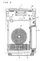
- FIG. 2 is a front view of an air cleaner main unit.
- FIG. 3 is a cross-sectional view of the air cleaner main unit.
- FIG. 4A shows one example of a specific state.
- FIG. 4B shows one example of a specific state.
- FIG. 5 shows an exemplary impureness level evaluation table.
- FIG. 6 shows relation between a fan motor output and a voltage applied to the ion generator for each drive mode of the ion generator.
- FIG. 7 shows an exemplary fan level determination table in an automatic mode.
- FIG. 8 shows relation between the fan level and an amount of humidification.
- FIG. 9 shows residual rate of airborne fungi in a time-series manner.
- FIG. 10 is a first diagram of a result of a deodorization test.
- FIG. 11 is a second diagram of a result of a deodorization test.
- FIG. 12 is a third diagram of a result of a deodorization test.
- FIG. 13 is a fourth diagram of a result of a deodorization test.
- FIG. 14 is an enlarged view of an operation portion of the air cleaner.
- FIG. 15 is a plan view of a remote controller.
- FIG. 16 is a circuit block diagram of the air cleaner in the present embodiment.
- FIG. 17 is a schematic diagram of a configuration of the ion generator.
- FIG. 18 is a circuit diagram of a voltage application circuit.
- FIG. 19A is a diagram illustrating a voltage pulse output from the voltage application circuit.
- FIG. 19B is a diagram illustrating a voltage pulse output from the voltage application circuit.
- FIG. 20 is a circuit diagram of a variation of the voltage application circuit.
- FIG. 21A is a diagram illustrating a voltage pulse output from the variation of the voltage application circuit.
- FIG. 21B is a diagram illustrating a voltage pulse output from the variation of the voltage application circuit.
- FIG. 22 shows a variation of the ion generator.
- FIG. 23 is a circuit diagram of a voltage application circuit connected to the variation of the ion generator.
- FIG. 24 is a flowchart showing processing performed in a control unit in the automatic mode.
- 1 air cleaner main unit 2 a inlet port; 6 a , 6 b outlet port; 10 , 10 A ion generator; 20 , 20 a , 20 b voltage application circuit; 103 operation portion; 104 operation switch button; 115 monitor indicator light; 130 remote controller; 150 control unit; 151 temperature sensor; 152 humidity sensor; 153 dust sensor; and 154 odor sensor.
- FIG. 1 is an exploded perspective view of an air cleaner incorporating an ion generator
- FIG. 2 is a front view of a main unit of the air cleaner in FIG. 1
- FIG. 3 is a cross-sectional view of the main unit of the air cleaner in FIG. 1 .
- the air cleaner incorporating the ion generator includes a main unit 1 of the air cleaner, a front panel 2 of the main unit, a filter portion 3 consisting of a plurality of types of filters, a fan motor 4 , a turbo fan 5 , a tank 44 , a humidifying filter 41 , a first outlet port 6 a , a second outlet port 6 b , an ion generator 10 , an operation portion 103 attaining a function to display an operation status, an inlet port 2 a in front panel 2 , and a remote controller 130 operated in order to send a signal for remote control of an operation of the air cleaner to operation portion 103 .
- Main unit 1 of the air cleaner is structured such that front panel 2 is provided to cover a part of the front face of main unit 1 .
- main unit 1 When viewed from the front, main unit 1 has a rectangular opening serving as a housing implemented by a hollow portion for housing filter portion 3 . Holes 24 for passing the air that has passed through filter portion 3 are radially formed on a bottom surface of the housing. Behind radial holes 24 , turbo fan 5 and fan motor 4 for rotating the turbo fan are disposed. Above turbo fan 5 , first outlet port 6 a and second outlet port 6 b for releasing the air to the room are provided. Ion generator 10 is arranged at some position in an airflow path 25 above turbo fan 5 .
- Front panel 2 is attached in such a manner that it is engaged to main unit 1 with a prescribed gap therefrom, and inlet port 2 a for taking the air into the room is formed in a central portion in a vertically extending manner. Front panel 2 may be attached to main unit 1 such that the air in the room is taken in also through a gap between front panel 2 and main unit 1 .
- filter portion 3 consists of three types of filters; a prefilter 3 a , a deodorizing filter 3 b , and a dust collection filter 3 c .
- These filters are housed in the hollow portion on the front face of main unit 1 in such a manner that they are housed in a filter frame 34 in that order from a side of inlet port 2 a .
- Prefilter 3 a collects large particles of dust or dirt
- deodorizing filter 3 b adsorbs odorous substances such as acetaldehyde, ammonia, acetic acid or the like
- dust collection filter 3 c collects dust or dirt in the air with a HEPA sheet.
- Filter portion 3 is structured in the above-described manner, such that prefilter 3 a collects dust or dirt in the air in the room that has been taken in, deodorizing filter 3 b adsorbs odorous substances in the air such as acetaldehyde, ammonia, acetic acid or the like, and finally dust collection filter 3 c collects fine dust or dirt that has passed through prefilter 3 a . Therefore, the air that has been filtered through filter portion 3 has the odor and the dust or dirt eliminated.
- Fan motor 4 rotating turbo fan 5 for taking in the air in the room is arranged downstream of filter portion 3 .
- Turbo fan 5 has a blade extending in a radial direction and bent rearward. Turbo fan 5 formed in such a manner attains highest static pressure and silence. Placing importance on controllability, a direct-current motor is used as fan motor 4 . Fan motor 4 in the present embodiment can switch the fan level in six levels.
- removable tank 44 for storing water is accommodated in one side portion of air cleaner main unit 1 .
- a water feed port in a lower portion of tank 44 is connected to a tray 43 .
- the water stored in tank 44 flows through the water feed port to tray 43 , and is supplied to tray 43 .
- the water stored in tray 43 has the surface maintained at a prescribed level.
- Humidifying filter 41 is supported by an upper cover 42 covering an upper surface of tray 43 . A lower portion of humidifying filter 41 is partially immersed in the water stored in tray 43 . Humidifying filter 41 is arranged downstream of filter portion 3 and upstream of turbo fan 5 . Humidifying filter 41 is disposed at a position closer to inlet port 2 a than ion generator 10 .
- Humidifying filter 41 absorbs water stored in tray 43 and becomes wet. When humidifying filter 41 is blown by the wind in such a state, the water contained in humidifying filter 41 is vaporized. When turbo fan 5 rotates, the air flows and the air is taken in through inlet port 11 a . A part of the air that has passed through filter portion 3 passes through humidifying filter 41 , and is transported to ion generator 10 . Thereafter, the air exits through first outlet port 6 a or second outlet port 6 b to the room.
- Air cleaner main unit 1 has a temperature sensor 151 , a humidity sensor 152 , a dust sensor 153 , and an odor sensor 154 above the housing for housing filter portion 3 .
- Dust sensor 153 is a particle sensor for detecting an airborne particle.
- Odor sensor 154 is a well-known sensor utilizing such a characteristic that a resistance value is varied when a gas component adsorbs on a surface of the sensor implemented by a metal oxide semiconductor.
- the air cleaner can be driven in five operation modes of an automatic mode, a 15-minute high-fan-level mode, a pollen mode, a silent mode, and a quick mode.
- the automatic mode refers to an operation mode in which ion generator 10 and fan motor 4 are controlled based on temperature, humidity and impureness level detected by temperature sensor 151 , humidity sensor 152 , dust sensor 153 , and odor sensor 154 .
- the automatic mode will be described in detail later.
- the 15-minute high-fan-level mode, the pollen mode, the silent mode, and the quick mode represent a drive mode of fan motor 4 , that is, an operation mode in which fan motor 4 is controlled to vary the fan level in terms of time.
- turbo fan 5 is driven at a high fan level for 15 minutes (fan level ) and thereafter the mode is switched to the automatic mode.
- turbo fan 5 operates at a fan level “high (fan level 5 )” for 10 minutes, and thereafter repeats the operation at fan level “medium (fan level 4 )” and fan level “high (fan level 5 )”.
- turbo fan 5 supplies brez wind and the operation is quiet.
- turbo fan 5 operates at fan level “maximum (fan level 6 )”.
- the drive mode of ion generator 10 includes an ion control mode and a clean mode.
- the ion control mode refers to a mode in which negative ions in an amount larger than that of positive ions are generated from ion generator 10 , or to a mode in which solely negative ions are generated.
- the clean mode refers to a mode in which positive ions and negative ions are generated in a substantially equal amount from ion generator 10 .
- the impureness level is calculated based on outputs from dust sensor 153 and odor sensor 154 , and the fan level is determined based on the impureness level.
- whether or not the temperature and the humidity detected by temperature sensor 151 and humidity sensor 152 attain a specific state is determined.
- the drive mode of ion generator 10 is determined based on whether the temperature and the humidity attain the specific state and on the impureness level. If the impureness level is lowest and the temperature and the humidity do not attain the specific state, the ion control mode is set. Otherwise, the clean mode is set. In addition, if the temperature and the humidity attain the specific state, a monitor mode is set.
- the clean mode out of the drive modes of ion generator 10 includes the monitor mode.
- the monitor mode is one type of the clean mode.
- a monitor purification mode refers to a drive mode of ion generator 10 when the temperature detected by temperature sensor 151 and the humidity detected by humidity sensor 152 attain the specific state.
- a state in which the temperature detected by temperature sensor 151 and the humidity detected by humidity sensor 152 do not attain the specific state is referred to as a normal state.
- the drive mode of ion generator 10 is set to the monitor mode when the temperature and the humidity attain the specific state, in which case, positive and negative ions are generated in an amount larger than in the normal state.
- the ordinate represents temperature and the abscissa represents humidity, thereby representing a region determined by the temperature and the humidity.
- the specific state includes a first region where the temperature is not lower than 24° C. and not higher than 34° C. and the humidity is not lower than 0% and not higher than 25%, a second region where the temperature is not lower than 0° C. and not higher than 24° C. and the humidity is not lower than 0% and not higher than 40%, and a third region where the temperature is not lower than 0° C. and not higher than 13° C. and the humidity is not lower than 40% and not higher than 100%.
- the first to third regions represent regions where viruses tend to be active.
- the second region represents an environment where allergens are likely to float.
- FIG. 5 shows an exemplary impureness level evaluation table.
- the impureness level evaluation table is stored in advance in a read-only memory (ROM) of the air cleaner.
- the impureness level evaluation table associates odor sensor output levels, dust sensor output levels and results of addition of values from both sensors with the impureness level for storage.
- output levels of odor sensor 154 ranges from 0 to 3
- output levels of dust sensor 153 ranges from 0 to 3. That is, an amount of odor and dust is output in 4 levels.
- the addition result represents the sum of the odor sensor output level and the dust sensor output level. The addition result ranges from 0 to 6.
- the impureness level is associated with the odor sensor output level and the dust sensor output level. Even when the addition results are the same, the impureness level may be different. For example, when the odor sensor output level attains to 1 and the dust sensor output level attains to 2, the addition result is 3 and this example is associated with the impureness level of 1. On the other hand, when the odor sensor output level attains 3 and the dust sensor output level attains 0, this example is associated with the impureness level of 2 in spite of the addition result of 3. This is because the odor sensor output level attains to 3, which indicates that an amount of substance causing odor is largest. In such a case, the impureness level is determined as 2, not 1.
- the impureness level has ranged in 3 levels of 0 to 2 here, the impureness level is not limited to such an example. A larger or smaller number of levels may be set, and two levels may be set, for example.
- the impureness level has been detected based on the output values from two sensors of odor sensor 154 and dust sensor 153 in the present embodiment, any one sensor output may be used to detect the impureness level.
- FIG. 6 shows relation between a fan motor output and a voltage applied to the ion generator for each drive mode of the ion generator.
- the voltage applied to ion generator 10 when duty is varied is exemplarily shown.
- the drive mode is set to the clean mode and when comparison is made between in the monitor mode and not in the monitor mode, duty is larger in the monitor mode, even though the fan level is the same. Therefore, positive and negative ions are generated in an amount larger than when not in the monitor mode.
- the drive mode of the ion generator is set to the clean mode, it is the positive and negative ions that are generated from ion generator 10 . Meanwhile, in the ion control mode, negative ions are generated from ion generator 10 in an amount larger than that of positive ions.
- an amount of ions generated from ion generator 10 in the present embodiment refers to a ratio between positive ions and negative ions in the air, and relates to the output of fan motor 5 .
- the output of fan motor 5 is represented by the fan level, which is categorized into 6 levels from fan level 1 to fan level 6 .
- Fan speed is higher at fan level 6 than at fan level 1 .
- the discharge noise from the ion generator and the voltage duty are preferably low.
- the wind noise is also great. Therefore, even if the discharge noise from the ion generator is great, it does not considerably affect the overall operation noise. Therefore, by setting duty 100% at fan level 5 or 6 , quietness and desired ion concentration can be realized without much affecting the overall operation noise.
- FIG. 7 shows an exemplary fan level determination table in the automatic mode.
- the fan level is determined based on the impureness level.
- fan level 1 is set for both of the normal state and the specific state.
- fan level 3 is set for the normal state and fan level 4 is set for the specific state.
- fan level 5 is set for the normal state and fan level 6 is set for the specific state.
- impureness that is, when the impureness level is determined as at least 1, the fan level in the specific state is set to be higher than the fan level in the normal state. This is because, the larger an amount of water supplied to ion generator 10 is, the longer the residual period of generated cluster ions is.
- the fan level is raised, an amount of air that passes through humidifying filter 41 is increased, whereby a larger amount of water is vaporized. Therefore, an amount of water supplied to ion generator 10 is increased.
- FIG. 8 shows relation between the fan level and an amount of humidification. As shown in FIG. 8 , it can be seen that, as the fan level is raised, the amount of humidification (the amount of vaporized water) is increased.
- FIG. 9 shows a residual rate of airborne fungi in a time-series manner.
- a dotted line 301 A represents a residual rate of airborne fungi in a natural state
- a solid line 301 B represents a residual rate of airborne fungi when positive and negative ions are generated from ion generator 10
- a solid line 301 C represents a residual rate of airborne fungi when positive and negative ions are generated while humidified air is supplied to ion generator 10 .
- FIGS. 10 to 13 show results of a deodorization test.
- FIG. 10 shows a test result as a whole
- FIG. 11 shows a residual rate of ammonia
- FIG. 12 shows a residual rate of acetaldehyde
- FIG. 13 shows a residual rate of acetic acid.
- a solid line 302 A represents a residual rate of an odorous substance when positive and negative ions are generated from ion generator 10
- a solid line 302 B represents a residual rate of an odorous substance when positive and negative ions are generated while humidified air is supplied to ion generator 10 .
- FIG. 14 is an enlarged view of operation portion 103 of the air cleaner.
- Operation portion 103 includes: a power button 106 for turning on/off main unit 1 ; a light receiving portion 105 for receiving an infrared ray from remote controller 130 ; a mist unit maintenance indicator light 111 for notifying a user of a time to clean the humidifying filter; a deodorizing filter cleaning indicator light 112 for notifying the user of a time to clean filter portion 3 ; a mist indicator light 113 indicating an operation mode of the air cleaner; a clean sign indicator light 114 indicating impureness level of the air in the room; a monitor indicator light 115 for displaying a state of the temperature and humidity in the room; a cluster ion indicator light 116 indicating a drive state of ion generator 10 ; an automatic mode indicator light 117 a indicating an operation mode of the air cleaner; a 15-minute high-fan-level mode indicator light 117 b , a pollen mode indicator light 117 c
- Operation switch button 104 is operated for switching the operation mode of main unit 1 .
- power button 105 When power button 105 is pressed, the operation is started in the automatic operation mode.
- automatic mode indicator light 117 a illuminates.
- the operation mode is sequentially switched to the automatic mode, the 15-minute high-fan-level mode, the pollen mode, the silent mode, the quick mode, the automatic mode, and so on, and corresponding to the switched operation mode, the indicator light illuminates sequentially in the order of automatic mode indicator light 117 a, 15-minute high-fan-level mode indicator light 117 b , pollen mode indicator light 117 c , silent mode indicator light 117 d , quick mode indicator light 117 e , automatic mode indicator light 117 a , and so on.
- Deodorizing filter cleaning indicator light 112 illuminates when an accumulated operation time of the air cleaner exceeds a predetermined deodorizing filter cleaning time, and otherwise it turns off. In this manner, the user can be notified of timing to clean deodorizing filter 3 b .
- the accumulated operation time is reset to zero by means of a reset button provided next to deodorizing filter cleaning indicator light 112 .
- Mist unit maintenance indicator light 111 illuminates when an accumulated operation time of the air cleaner while water is contained in tank 44 and tray 43 , that is, an accumulated humidifying operation time, exceeds a predetermined humidifying filter cleaning time, and otherwise it turns off. In this manner, the user can be notified of timing to clean humidifying filter 41 .
- the accumulated operation time is reset to zero by means of a reset button provided next to mist unit maintenance indicator light 111 .
- Off timer indicator light 120 indicates timer setting in accordance with the instruction from the user.
- One of two off timer indicator lights 120 illuminates in accordance with the number of times of instruction given by the user.
- Mist indicator light 113 illuminates when the water is contained in tray 43 .
- Clean sign indicator light 114 indicates impureness level of the air in the room. Clean sign indicator light 114 illuminates in green, corresponding to impureness level “0” indicating the lowest impureness level; it illuminates in orange, corresponding to impureness level “1” indicating an intermediate level of impureness; and it illuminates in red, corresponding to impureness level “2” indicating the highest impureness level.
- Cluster ion indicator light 116 indicates a drive mode of ion generator 10 .
- Cluster ion indicator light 116 illuminates in green when ion generator 10 operates in the ion control mode. In the clean mode, cluster ion indicator light 116 flashes in blue in a cycle of 5 seconds in the monitor mode, whereas it illuminates in blue when not in the monitor mode. When ion generator 10 is not driven, cluster ion indicator light 116 turns off.
- Monitor indicator light 115 illuminates when the temperature and the humidity attain the specific state. Therefore, the user is notified that the room is in the environment where viruses are likely to proliferate. At this time point, the user operates operation switch button 104 to switch the operation mode to the automatic mode, so that the drive mode of ion generator 10 is switched to the monitor mode in the clean mode and the fan level is raised. Therefore, an amount of positive and negative ions generated from ion generator 10 is increased and an amount of water supplied to ion generator 10 is increased, whereby the residual period of generated positive and negative ions is extended. A larger amount of ions are thus released to the room and higher concentration of the positive and negative ions in the room can be achieved.
- FIG. 15 is a plan view of remote controller 130 .
- Remote controller 130 includes: a power switch 106 A for turning on/off the power of the air cleaner; a filter reset button 129 for resetting the accumulated operation time after cleaning the deodorizing filter; an automatic mode button 116 A for setting the operation mode of the air cleaner to the automatic mode; a fan level button 119 A for switching to the manual mode and designating a fan level of fan motor 4 ; a pollen mode button 118 A for setting the pollen mode; an off-timer button 122 A for setting an off-timer; a daily mode button 121 for setting a daily mode; a sleep automatic mode button 122 for setting a sleep automatic mode; a quick mode button 123 for setting the quick mode; a display switch button 124 for switching on/off display on operation portion 103 ; and setting buttons 125 to 128 for manually setting the drive mode of ion generator 10 .
- Remote controller 130 outputs a signal of infrared ray in accordance with the pressed switch.
- the air cleaner is driven in response to the signal of infrared ray.
- a communication medium between remote controller 130 and the air cleaner is not limited to the infrared ray.
- an electromagnetic wave or an acoustic wave can be employed, and any means allowing radio communication may be used, without limited to the infrared ray.
- the air cleaner When automatic mode button 116 A is pressed, the air cleaner operates in the automatic mode.
- fan level button 119 A is pressed, the air cleaner changes the fan level in the order of silent, medium and maximum every time fan level button 119 A is pressed.
- pollen mode button 118 A is pressed, the air cleaner operates in the pollen mode. Every time off-timer button 122 A is pressed, the off-timer is sequentially set to either 1 hour or 4 hours.
- the air cleaner When daily mode button 121 is pressed, the air cleaner operates in the operation mode that has been stored in advance. When sleep automatic mode button 122 is pressed, the air cleaner operates in the silent mode. When quick mode button 123 is pressed, the air cleaner operates in the quick mode.
- any of setting buttons 125 to 128 is pressed, the drive mode of ion generator 10 is switched.
- setting button 126 is pressed, application of a voltage to ion generator 10 is stopped so as to stop drive of ion generator 10 .
- setting button 125 is pressed, ion generator 10 is driven in the clean mode.
- setting button 127 is pressed, ion generator 10 is driven in the ion control mode.
- setting button 128 is pressed, an air cleaner 100 is driven in the automatic mode
- FIG. 16 is a circuit block diagram of the air cleaner in the present embodiment.
- a control unit 150 for overall control includes temperature sensor 151 , humidity sensor 152 , dust sensor 153 , odor sensor 154 , a temperature setting unit 155 for setting temperature, a humidity setting unit 156 for setting humidity, a voltage application circuit 20 for applying a voltage to ion generator 10 , and a motor drive circuit 31 for controlling drive of fan motor 4 .
- Ion generator 10 is connected to voltage application circuit 20
- fan motor 4 is connected to motor drive circuit 31 .
- Temperature setting unit 155 and humidity setting unit 156 serve as input portions for setting threshold values used for determining the specific state. Temperature setting unit 155 and humidity setting unit 156 are implemented, for example, by a button switch or a slide switch provided in main unit 1 and serve to set the temperature and the humidity. Temperature setting unit 155 and humidity setting unit 156 may be provided in remote controller 130 so that the set temperature and humidity are transmitted from remote controller 130 to the air cleaner.
- Motor drive circuit 31 switches the number of revolutions of fan motor 4 in 6 levels, in accordance with the instruction from control unit 150 .
- voltage application circuit 20 drives ion generator 10 in accordance with the instruction from control unit 150 .
- FIG. 17 schematically shows a configuration of the ion generator.
- FIG. 17(A) is a plan view of ion generator 10
- FIG. 17(B) is a side view of the same.
- Ion generator 10 includes a dielectric 11 , a discharge electrode 12 a , an induction electrode 12 b , and a coating layer 13 .
- discharge electrode 12 a and induction electrode 12 b When a voltage is applied to discharge electrode 12 a and induction electrode 12 b , discharge occurs between discharge electrode 12 a and induction electrode 12 b , whereby both positive and negative ions or negative ions are generated.
- Dielectric 11 is implemented as a plate-like component formed by laminating an upper dielectric 11 a and a lower dielectric 11 b .
- Discharge electrode 12 a is formed integrally with upper dielectric 11 a on the surface of upper dielectric 11 a .
- Induction electrode 12 b is formed between upper dielectric 11 a and lower dielectric 11 b , and arranged in a manner facing discharge electrode 12 a . Desirably, insulation resistance between discharge electrode 12 a and induction electrode 12 b is uniform, and discharge electrode 12 a is parallel to induction electrode 12 b.
- discharge electrode 12 a and induction electrode 12 b are arranged on a surface and a back surface of upper dielectric 11 a respectively, in a manner opposed to each other. Accordingly, a distance between discharge electrode 12 a and induction electrode 12 b can be constant. In this manner, a discharge state between discharge electrode 12 a and induction electrode 12 b is stabilized, and both positive and negative ions or negative ions can suitably be generated.
- a discharge electrode contact 12 e is electrically connected to discharge electrode 12 a via a connection terminal 12 c provided on the surface where discharge electrode 12 a is located.
- One end of a conductive lead is connected to discharge electrode contact 12 e while the other end thereof is connected to voltage application circuit 20 , so that discharge electrode 12 a and voltage application circuit 20 can electrically be connected.
- An induction electrode contact 12 f is electrically connected to induction electrode 12 b via a connection terminal 12 d provided on the surface where induction electrode 12 b is located.
- One end of a lead implemented by a copper wire is connected to induction electrode contact 12 f while the other end thereof is connected to voltage application circuit 20 , so that induction electrode 12 b and voltage application circuit 20 can electrically be connected.
- FIG. 18 is a circuit diagram of the voltage application circuit.
- voltage application circuit 20 includes an AC power supply 201 , a switching transformer 202 , a switch relay 203 , a resistor 204 , diodes 205 a to 205 d , a capacitor 206 , and an SIDAC® 207 .
- SIDAC® 207 is one type of silicon control rectifier SCR and manufactured by Shindengen Electric Manufacturing Co., Ltd.
- AC power supply 201 is connected to the anode of diode 205 a and the cathode of diode 205 c , while the other end thereof is connected to a common terminal 203 a of switch relay 203 .
- the cathode of diode 205 a is connected to one end of resistor 204 and the cathode of diode 205 d .
- the other end of resistor 204 is connected to one end of a primary coil L 1 of transformer 202 and one end of capacitor 206 .
- the other end of primary coil L 1 is connected to the anode of SIDAC® 207 .
- capacitor 206 is connected to the cathode of SIDAC® 207 , of which connection node is connected to one selection terminal 203 b in switch relay 203 and respective anodes of diodes 205 b and 205 c .
- the cathode of diode 205 b is connected to the anode of diode 205 d , of which connection node is connected to the other selection terminal 203 c of switch relay 203 .
- One end of a secondary coil L 2 of transformer 202 is connected to discharge electrode contact 12 e of ion generator 10 , while the other end thereof is connected to a common terminal 208 a of a relay 208 .
- One selection terminal 208 c in relay 208 is connected to the anode of a diode 209 , and the cathode of diode 209 is connected to induction electrode contact 12 f .
- Induction electrode contact 12 f of ion generator 10 is connected to the other selection terminal 208 b in relay 208 and the anode of diode 209 .
- selection terminal 203 b is selected in switch relay 203 and selection terminal 208 b is selected in switch relay 208 .
- an output voltage of AC power supply 201 is subjected to half-wave rectification in diode 205 a , then lowered by resistor 204 , and applied to capacitor 206 .
- capacitor 206 is charged and a voltage across the capacitor attains a prescribed threshold value, SIDAC® 207 attains an on state and the charged voltage of capacitor 206 is discharged. Accordingly, a current flows through primary coil L 1 in transformer 202 to transmit energy to secondary coil L 2 , whereby a pulse voltage is applied to ion generator 10 .
- SIDAC® 207 attains an off state and charge of capacitor 206 is started again.
- an AC impulse voltage in FIG. 19A (pp (Peak-to-Peak) value: 3.5 [kV], the number of times of discharge: 120 [times per second], for example) is applied between discharge electrode 12 a and induction electrode 12 b of ion generator 10 .
- corona discharge occurs in the vicinity of ion generator 10 , and the ambient air is ionized. That is, H + (H 2 O) m which is a positive ion is generated when a positive voltage is applied, while O 2 ⁇ (H 2 O) n which is a negative ion is generated when a negative voltage is applied (m, n represent 0 or any natural number).
- H + (H 2 O) m 0 or any natural number
- O 2 ⁇ (H 2 O) n 0 or any natural number
- H + (H 2 O) m and O 2 ⁇ (H 2 O) n are released to a space by means of the fan or the like and adhere to the surface of airborne fungi, followed by chemical reaction.
- H 2 O 2 or .OH which is an active species is generated.
- H 2 O 2 or .OH exhibits extremely strong activity, airborne fungi in the air are enclosed and inactivated.
- .OH is a type of active species and represents radical OH.
- an effect to inactivate airborne fungi or the like can be obtained as a result of release of positive and negative ions shown above.
- fan motor 4 is driven so that positive and negative ions generated by ion generator 10 can be released to the outside of the main unit.
- An action of such positive and negative ions can inactivate molds and fungi in the air and suppress proliferation thereof.
- the positive and negative ions also serve to inactivate viruses such as Coxsackie virus or polio virus, thereby preventing contamination due to introduction of these viruses. Furthermore, as it has been confirmed that the positive and negative ions serve to decompose molecules causing odor, the positive and negative ions can be utilized for deodorization of a space.
- Wind was generated from turbo fan 5 toward ion generator 10 , and an amount of positive ions and negative ions that arrived at an ion counter positioned approximately 25 cm away from ion generator 10 was measured.
- the ion counter counted approximately three hundred thousand (per cc), with regard to each of positive ion and negative ion.
- selection terminal 203 c is selected in switch relay 203
- selection terminal 208 b is selected in switch relay 208 .
- the output voltage of AC power supply 201 is subjected to full-wave rectification in a diode bridge constituted of diodes 205 a to 205 d , then lowered by resistor 204 , and applied to capacitor 206 . Therefore, an AC impulse voltage of discharge frequency higher than when not in the specific state (pp value: 3.5 [kV], the number of times of discharge: 240 [times per second], for example) is applied between discharge electrode 12 a and induction electrode 12 b of ion generator 10 , as shown in FIG. 19B .
- an amount of ions was measured under the condition described above.
- the ion counter counted approximately five hundred thousand per cc, with regard to each of positive ion and negative ion. That is, an amount of ions 1.7 times as large as that in the normal state, that is, when not in the specific state, was measured.
- connection node of the cathode of diode 205 b and the anode of diode 205 d is connected to the other end of AC power supply 201 instead of switch relay 203 , a switch is connected in series to the anode or the cathode of diode 205 c or diode 205 d , and the switch is controlled in accordance with the drive mode.
- selection terminal 203 b is selected in switch relay 203
- selection terminal 208 c is selected in switch relay 208 .
- FIG. 20 is a circuit diagram of a variation of the voltage application circuit. Referring to FIG. 20 , this voltage application circuit is different from voltage application circuit 20 in FIG. 18 in a circuit configuration between AC power supply 201 and primary coil L 1 in switching transformer 202 . As other circuits are the same, description thereof will not repeated.
- One end of AC power supply 201 is connected to one end of a resistor 214 , while the other end of resistor 214 is connected the anode of a diode 215 .
- the other end of AC power supply 201 is connected to the cathode of SIDAC® 207 , one end of capacitor 106 a , and one end of a relay 213 .
- the cathode of diode 215 is connected to one ends of capacitors 206 a , 206 b and primary coil L 1 .
- the other end of capacitor 206 b is connected to the other end of relay 213 .
- a voltage application circuit 20 a in the variation configured in the above-described manner when the specific state is not attained, relay 213 closes.
- the output voltage of AC power supply 201 is subjected to half-wave rectification in diode 215 , and thereafter applied to capacitors 206 a and 206 b .
- capacitors 206 a and 206 b are charged and voltages across the capacitors attain a prescribed threshold value
- SIDAC® 207 attains an on state and the charged voltages of capacitors 206 a and 206 b are discharged. Accordingly, a current flows through primary coil L 1 in transformer 202 to transmit energy to secondary coil L 2 , whereby a pulse voltage is applied to ion generator 10 .
- SIDAC® 207 attains an off state and charge of capacitors 206 a and 206 b is started again.
- relay 213 opens.
- the output voltage of AC power supply 201 is subjected to half-wave rectification in diode 215 , and applied solely to capacitor 206 a .
- SIDAC® 207 attains an on state and the charged voltage of capacitor 206 a is discharged. Accordingly, a current flows through primary coil L 1 in transformer 202 to transmit energy to secondary coil L 2 , whereby a pulse voltage is applied to ion generator 10 .
- SIDAC® 207 attains an off state and charge of capacitor 206 a is started again.
- FIGS. 21A and 21B show waveforms of voltages output from voltage application circuit 20 a in the variation.
- FIG. 21A shows a waveform when relay 213 is closed, and illustrates a waveform of a voltage that has been subjected to half-wave rectification in diode 215 and a waveform of a voltage pulse applied to ion generator 10 .
- FIG. 21B illustrates a waveform of a voltage that has been subjected to half-wave rectification when relay 213 is open and a waveform of a voltage pulse applied to ion generator 10
- half-wave rectification and full-wave rectification have been switched by switching switch 203 .
- switching between full-wave rectification and half-wave rectification may be employed. In such a case, when the voltage pulse of low discharge frequency is applied to ion generator 10 , the voltage that has been subjected to half-wave rectification is used and relay 213 is closed. Meanwhile, when a voltage pulse of high discharge frequency is applied to ion generator 10 , full-wave rectification is used and relay 213 is opened.
- FIG. 22 shows variations of the ion generator.
- an ion generator 10 A in this variation is different from ion generator 10 described above in that it includes a first discharge portion 21 constituted of a discharge electrode 21 a and an induction electrode 21 b , and a second discharge portion 22 constituted of a discharge electrode 22 a and an induction electrode 22 b .
- ion generator 10 A in this variation is different in including two discharge portions, that is, first discharge portion 21 and second discharge portion 22 .
- induction electrodes 21 b and 22 b are formed on a surface of lower dielectric 11 b
- discharge electrodes 21 a and 22 a are formed on a surface of upper dielectric 11 a
- the surface of upper dielectric 11 a is covered with coating layer 13 .
- upper dielectric 11 a is stacked on the surface of lower dielectric 11 b where induction electrodes 21 b and 22 b are formed.
- Discharge electrode 21 a and induction electrode 21 b in first discharge portion 21 are arranged in positions opposed to each other, while discharge electrode 22 a and induction electrode 22 b in second discharge portion 22 are arranged in positions opposed to each other.
- connection terminal 21 c of discharge electrode 21 a is connected to discharge electrode contact 21 e , which is connected to a voltage application circuit 20 B via a lead.
- connection terminal 21 d of induction electrode 21 b is connected to induction electrode contact 21 f , which is connected to voltage application circuit 20 B via a lead.
- connection terminal 22 c of discharge electrode 22 a is connected to discharge electrode contact 22 e , which is connected to voltage application circuit 20 B via a lead.
- connection terminal 22 d of induction electrode 22 b is connected to induction electrode contact 22 f , which is connected to voltage application circuit 20 B via a lead.
- FIG. 23 is a circuit diagram of voltage application circuit 20 B connected to ion generator 10 A in the variation.
- voltage application circuit 20 B includes AC power supply 201 , a transformer 222 , a switch relay 233 , resistors 224 , 225 , diodes 226 to 230 , capacitors 231 a , 231 b , and an SIDAC® 232 .
- One end of AC power supply 201 is connected to the anode of diode 226 via resistor 224 .
- the cathode of diode 226 is connected to one end of a first coil 222 a implementing a primary side of transformer 222 , the anode of diode 227 , and the anode of SIDAC® 232 .
- the other end of first coil 222 a is connected to the cathode of diode 227 , of which connection node is connected to one ends of capacitors 231 a and 231 b .
- the cathode of SIDAC® 232 , the other end of capacitor 231 a , and one end 233 a of relay 233 are connected to one another, of which connection node is connected to the other end of AC power supply 201 .
- the other end 233 b of relay 233 is connected to the other end of capacitor 231 b.
- One end of a second coil 222 b implementing a secondary side of transformer 222 is connected to discharge electrode contact 21 e of first discharge portion 21 , while the other end of second coil 222 b is connected to induction electrode contact 21 f of first discharge portion 21 , the cathode of diode 229 , and the anode of diode 230 .
- the anode of diode 229 is connected to one selection terminal 223 a of switch relay 223
- the cathode of diode 230 is connected to the other selection terminal 223 b of switch relay 223 .
- One end of a third coil 222 c implementing the secondary side of transformer 222 is connected to discharge electrode contact 22 e of second discharge portion 22 , while the other end of third coil 222 c is connected to induction electrode contact 22 f of second discharge portion 22 and the anode of diode 228 .
- a common terminal 223 c of switch relay 223 is connected to the cathode of diode 228 , of which connection node is connected to the other end of AC power supply 201 via resistor 225 .
- relay 233 closes and selection terminal 223 a is selected in switch relay 223 .
- a positive DC impulse voltage is applied between discharge electrode contact 21 e and induction electrode contact 21 f in first discharge portion 21
- a negative DC impulse voltage is applied between discharge electrode contact 22 e and induction electrode contact 22 f in second discharge portion 22 .
- H + (H 2 O) m which is a positive ion is generated in the vicinity of first discharge portion 21 to which the positive DC impulse has been applied
- O 2 ⁇ (H 2 O) n which is a negative ion is generated in the vicinity of second discharge portion 22 to which the negative DC impulse has been applied
- m, n represent 0 or any natural number
- relay 233 is opened and selection terminal 223 a is selected in switch relay 223 .
- solely capacitor 231 a is charged. Therefore, a time period until the voltage applied to SIDAC® 232 attains the prescribed threshold value is shortened. Accordingly, discharge frequencies of the positive DC impulse voltage applied to first discharge portion 21 and the negative DC impulse voltage applied to second discharge portion 22 are increased. In this manner, a larger amount of positive ions is generated in first discharge portion 21 , and a larger amount of negative ions is generated in second discharge portion 22 .
- relay 233 is closed and selection terminal 223 b is selected in switch relay 223 .
- the negative DC impulse voltage is applied to both first discharge portion 21 and second discharge portion 22 .
- O 2 ⁇ (H 2 O) n which is a negative ion (n represents 0 or any natural number) is generated in the vicinity of both first discharge portion 21 and second discharge portion 22 .
- FIG. 24 is a flowchart showing processing performed in the control unit in the automatic mode.
- the fan level is set based on the impureness level (steps S 01 to S 04 ).
- the impureness level is determined. If the impureness level is determined as “0”, fan level 1 is set (step S 02 ). If the impureness level is determined as “1”, fan level 3 is set (step S 03 ). If the impureness level is determined as “2”, fan level 5 is set (step S 04 ).
- step S 05 to S 08 Thereafter, whether or not the specific state is attained is determined (steps S 05 to S 08 ). If it is determined that the specific state is attained, the process proceeds to step S 12 . If it is determined that not the specific state but the normal state is attained, the process proceeds to step S 09 . Specifically, at step S 05 , the temperature and the humidity are detected by temperature sensor 151 and humidity sensor 152 (step S 05 ). If it is determined at step S 06 that the temperature is not higher than 34° C. and the humidity is not higher than 25%, it is determined that the specific state is attained and the process proceeds to step S 12 . Otherwise, the process proceeds to step S 07 . If it is determined at step S 07 that the temperature is not higher than 24° C.
- step S 08 If it is determined at step S 08 that the temperature is not higher than 13° C., it is determined that the specific state is attained and the process proceeds to step S 12 . Otherwise, the process proceeds to step S 09 .
- step S 09 If it is determined that the normal state is attained, whether or not the impureness level attains to 1 or higher is determined at step S 09 . If YES, the process proceeds to step S 10 . If NO, the process proceeds to step S 11 .
- step S 10 the drive mode of ion generator 10 is set to the clean mode. This clean mode is not the monitor mode. Therefore, an amount of positive and negative ions generated from ion generator 10 is smaller than in the monitor mode.
- step S 11 the drive mode of ion generator 10 is set to the ion control mode. Here, ion generator 10 generates negative ions in an amount larger than that of positive ions.
- the drive mode of ion generator 10 is set to the clean mode at step S 12 .
- This clean mode is the monitor mode. Therefore, an amount of positive and negative ions generated from ion generator 10 is larger than when not in the monitor mode.
- step S 13 whether or not the impureness level attains to 1 or higher is determined. If YES, the process proceeds to step S 14 . If NO, the process ends.
- the fan level set at steps S 02 to S 04 is raised. Specifically, fan level 3 is raised to fan level 4 , and fan level 5 is raised to fan level 6 . The fan level is raised to increase an amount of air that passes through humidifying filter 41 . Therefore, an amount of water supplied to ion generator 10 is increased. Consequently, the residual period of generated ions is extended and sterilizing effect is improved.
- humidifying filter 41 is arranged in the path from inlet port 2 a to outlet port 6 a , 6 b at a position closer to inlet port 2 a than ion generator 10 . Therefore, humidified air is supplied to ion generator 10 .
- water is supplied to ion generator 10 in an amount larger than in the normal state. Ions are surrounded by water molecules, whereby its residual period is extended. Therefore, the sterilizing effect can be improved.
- fan motor 4 is controlled to raise the fan level, so that water supplied to ion generator 10 is increased.
- the structure is thus simplified.
- ion generator 10 driven in the clean mode is driven in the monitor mode in which ions are generated in an amount larger than in the normal state. Therefore, a larger amount of ions can be released to the room.
- monitor indicator light 115 illuminates. Therefore, the user can know that the room is in the non-preferable environment where viruses are likely to proliferate. At this time point, the user operates operation switch button 104 of his/her own will, to switch the operation mode to the automatic mode. Then, in the air cleaner, the drive mode of ion generator 10 is set to the monitor mode in the clean mode and the fan level is raised. Higher concentration of positive and negative ions in the room can thus be achieved of user's own will.
Landscapes
- Engineering & Computer Science (AREA)
- Chemical & Material Sciences (AREA)
- Combustion & Propulsion (AREA)
- Mechanical Engineering (AREA)
- General Engineering & Computer Science (AREA)
- Human Computer Interaction (AREA)
- Health & Medical Sciences (AREA)
- Physics & Mathematics (AREA)
- Signal Processing (AREA)
- General Health & Medical Sciences (AREA)
- Epidemiology (AREA)
- Life Sciences & Earth Sciences (AREA)
- Animal Behavior & Ethology (AREA)
- Public Health (AREA)
- Veterinary Medicine (AREA)
- Mathematical Physics (AREA)
- Fuzzy Systems (AREA)
- Fluid Mechanics (AREA)
- Disinfection, Sterilisation Or Deodorisation Of Air (AREA)
- Air Conditioning Control Device (AREA)
- Air Humidification (AREA)
- Separation Of Particles Using Liquids (AREA)
Abstract
Description
H3O+(H2O)m+O2 −(H2O)n→.OH+½O2+(m+n+1)H2O (1)
H3O+(H2O)m+H3O+(H2O)m′+O2 −(H2O)n+O2 −(H2O)n′→2.OH+O2+(m+m′+n+n′+2)H2O (2)
H3O+(H2O)m+H3O+(H2O)m′+O2 −(H2O)n+O2 −(H2O)n′→H2O2+O2+(m+m′+n+n′+2)H2O (3)
Claims (9)
Applications Claiming Priority (3)
| Application Number | Priority Date | Filing Date | Title |
|---|---|---|---|
| JP2004241359A JP3795504B2 (en) | 2004-08-20 | 2004-08-20 | Air conditioner |
| JP2004-241359 | 2004-08-20 | ||
| PCT/JP2005/014296 WO2006018978A1 (en) | 2004-08-20 | 2005-08-04 | Air adjustment device |
Publications (2)
| Publication Number | Publication Date |
|---|---|
| US20080074824A1 US20080074824A1 (en) | 2008-03-27 |
| US7679879B2 true US7679879B2 (en) | 2010-03-16 |
Family
ID=35907368
Family Applications (1)
| Application Number | Title | Priority Date | Filing Date |
|---|---|---|---|
| US11/631,935 Expired - Fee Related US7679879B2 (en) | 2004-08-20 | 2005-08-04 | Air conditioning apparatus |
Country Status (7)
| Country | Link |
|---|---|
| US (1) | US7679879B2 (en) |
| EP (1) | EP1779873B1 (en) |
| JP (1) | JP3795504B2 (en) |
| KR (1) | KR100974726B1 (en) |
| CA (1) | CA2572422C (en) |
| MY (1) | MY143255A (en) |
| WO (1) | WO2006018978A1 (en) |
Cited By (19)
| Publication number | Priority date | Publication date | Assignee | Title |
|---|---|---|---|---|
| US20080217556A1 (en) * | 2007-03-07 | 2008-09-11 | Sharp Kabushiki Kaisha | Electronic apparatus |
| US20150143839A1 (en) * | 2012-07-05 | 2015-05-28 | Lg Electronics Inc. | Air conditioner |
| US9808754B2 (en) | 2014-02-14 | 2017-11-07 | Access Business Group International Llc | Air treatment system |
| US9919939B2 (en) | 2011-12-06 | 2018-03-20 | Delta Faucet Company | Ozone distribution in a faucet |
| US10054572B2 (en) | 2014-12-19 | 2018-08-21 | Carrier Corporation | Air purifying system and a method of using the same |
| US10512873B2 (en) | 2014-02-14 | 2019-12-24 | Access Business Group International Llc | Air treatment system |
| US20210162326A1 (en) * | 2019-12-02 | 2021-06-03 | Porvair Filtration Group Limited | Gas filtration apparatus |
| US11458214B2 (en) | 2015-12-21 | 2022-10-04 | Delta Faucet Company | Fluid delivery system including a disinfectant device |
| US11636870B2 (en) | 2020-08-20 | 2023-04-25 | Denso International America, Inc. | Smoking cessation systems and methods |
| US11760169B2 (en) | 2020-08-20 | 2023-09-19 | Denso International America, Inc. | Particulate control systems and methods for olfaction sensors |
| US11760170B2 (en) | 2020-08-20 | 2023-09-19 | Denso International America, Inc. | Olfaction sensor preservation systems and methods |
| US11813926B2 (en) | 2020-08-20 | 2023-11-14 | Denso International America, Inc. | Binding agent and olfaction sensor |
| US11828210B2 (en) | 2020-08-20 | 2023-11-28 | Denso International America, Inc. | Diagnostic systems and methods of vehicles using olfaction |
| US11881093B2 (en) | 2020-08-20 | 2024-01-23 | Denso International America, Inc. | Systems and methods for identifying smoking in vehicles |
| US11932080B2 (en) | 2020-08-20 | 2024-03-19 | Denso International America, Inc. | Diagnostic and recirculation control systems and methods |
| US12017506B2 (en) | 2020-08-20 | 2024-06-25 | Denso International America, Inc. | Passenger cabin air control systems and methods |
| US12251991B2 (en) | 2020-08-20 | 2025-03-18 | Denso International America, Inc. | Humidity control for olfaction sensors |
| US12269315B2 (en) | 2020-08-20 | 2025-04-08 | Denso International America, Inc. | Systems and methods for measuring and managing odor brought into rental vehicles |
| US12377711B2 (en) | 2020-08-20 | 2025-08-05 | Denso International America, Inc. | Vehicle feature control systems and methods based on smoking |
Families Citing this family (25)
| Publication number | Priority date | Publication date | Assignee | Title |
|---|---|---|---|---|
| ES2319478B1 (en) * | 2006-05-12 | 2010-01-25 | Bsh Electrodomesticos España, S.A. | APPARATUS FOR CLEANING AND AIR CONDITIONING. |
| JP4716927B2 (en) * | 2006-06-02 | 2011-07-06 | シャープ株式会社 | refrigerator |
| JP4831528B2 (en) * | 2006-07-21 | 2011-12-07 | 東芝ホームテクノ株式会社 | humidifier |
| JP4519815B2 (en) * | 2006-08-07 | 2010-08-04 | 三菱電機株式会社 | Air purifier with humidification function |
| JP4983530B2 (en) * | 2007-10-17 | 2012-07-25 | パナソニック株式会社 | Air cleaner |
| JP2010007871A (en) * | 2008-06-24 | 2010-01-14 | Daikin Ind Ltd | Ventilation device |
| US8885183B2 (en) * | 2009-07-22 | 2014-11-11 | Sharp Kabushiki Kaisha | Image forming system with an air cleaner that displays an operating state of the image forming apparatus |
| US9535407B2 (en) * | 2009-08-14 | 2017-01-03 | Opto Generic Devices, Inc. | Intelligent total air climate and cleaning conditioner |
| JP4703770B1 (en) * | 2010-02-19 | 2011-06-15 | シャープ株式会社 | Ion generator and method for determining presence / absence of ions |
| JP5520154B2 (en) * | 2010-07-22 | 2014-06-11 | アズビル株式会社 | Blower control device and method |
| JP2014025643A (en) * | 2012-07-26 | 2014-02-06 | Sharp Corp | Refrigerator |
| CN103542492A (en) * | 2013-08-23 | 2014-01-29 | 苏州康华净化系统工程有限公司 | Constant temperature and humidity control system |
| KR101554722B1 (en) * | 2015-01-23 | 2015-09-21 | 황용희 | Air conditioner having variable air volume control device |
| CN104807151B (en) * | 2015-05-27 | 2017-11-07 | 成都德麦科技有限公司 | A kind of thermostatic constant wet control system |
| CN107850332B (en) * | 2015-07-30 | 2020-09-25 | 三菱电机株式会社 | Storage cover and indoor unit of air conditioner provided with storage cover |
| EP3193417A1 (en) * | 2016-01-12 | 2017-07-19 | Naturion Pte. Ltd. | Ion generator device |
| KR20180065240A (en) * | 2016-12-07 | 2018-06-18 | 유버 주식회사 | Sterilization air cleaner and method for controlling the same |
| CN107477812A (en) * | 2017-09-21 | 2017-12-15 | 四川长虹电器股份有限公司 | Baby's surrounding air system and control method based on warming camera |
| CN108278663A (en) * | 2018-01-11 | 2018-07-13 | 广东美的制冷设备有限公司 | The control method and air conditioner of air conditioner |
| CN108662709A (en) * | 2018-04-27 | 2018-10-16 | 上海建工集团股份有限公司 | Fresh air filtration system based on outdoor PM2.5 concentration and air purification method |
| CN111380291B (en) * | 2018-12-28 | 2022-03-25 | 海尔智家股份有限公司 | Air-cooled refrigerator and sterilization method thereof |
| KR102216410B1 (en) | 2019-05-02 | 2021-02-16 | 엘지전자 주식회사 | Ion generator |
| EP3964759A1 (en) * | 2020-09-04 | 2022-03-09 | Novoa Diz, Susana | Device for generating hydroxyl radicals |
| KR102604293B1 (en) * | 2020-10-12 | 2023-11-20 | 어썸레이 주식회사 | Air sterilizer and air sterilizing method using it |
| CN117810910A (en) * | 2022-09-23 | 2024-04-02 | 开利公司 | Power loss detection circuit and control circuit for variable refrigerant flow system VRF |
Citations (16)
| Publication number | Priority date | Publication date | Assignee | Title |
|---|---|---|---|---|
| US4499031A (en) * | 1982-09-27 | 1985-02-12 | Allis-Chalmers Corp. | Evaporative gas treating system |
| US4686069A (en) * | 1985-06-26 | 1987-08-11 | Eltex-Elektrostatik Gesellschaft Mbh | Air humidifier |
| GB2254447A (en) | 1991-05-17 | 1992-10-07 | Norm Pacific Automat Corp | Interior atmosphere control system. |
| US5743465A (en) * | 1995-08-22 | 1998-04-28 | Samsung Electronics Co., Ltd. | Methods and apparatus for effecting wireless control of an air conditoner |
| JP2000081227A (en) | 1998-06-29 | 2000-03-21 | Yoshitaka Kimoto | Air conditioner and negative ion generator |
| JP2002089932A (en) | 2000-09-13 | 2002-03-27 | Sanyo Electric Co Ltd | Humidifier |
| JP2002203657A (en) | 2000-12-27 | 2002-07-19 | Daikin Ind Ltd | Ion generator |
| JP2002286356A (en) | 2001-03-28 | 2002-10-03 | Mitsubishi Electric Corp | Negative ion and ozone generator |
| JP2003056878A (en) | 2001-08-13 | 2003-02-26 | Daikin Ind Ltd | Air cleaner |
| JP2003083593A (en) | 2001-09-12 | 2003-03-19 | Sharp Corp | Mold control method and air conditioner |
| US20030086813A1 (en) | 2000-02-18 | 2003-05-08 | Lk Luftqualitat Ag | Method For The Treatment Of Air Of At Least One Room By Air Ionization |
| US20040023094A1 (en) * | 1999-12-24 | 2004-02-05 | Tatsuji Hatayama | Fuel cell power generating system |
| JP2004150734A (en) | 2002-10-31 | 2004-05-27 | Ricoh Elemex Corp | Air cleaner |
| JP2004181999A (en) | 2002-11-29 | 2004-07-02 | Nissan Motor Co Ltd | Vehicle air conditioner |
| JP2004232941A (en) | 2003-01-30 | 2004-08-19 | Hitachi Hometec Ltd | humidifier |
| US6985346B2 (en) * | 2003-01-29 | 2006-01-10 | Credence Technologies, Inc. | Method and device for controlling ionization |
-
2004
- 2004-08-20 JP JP2004241359A patent/JP3795504B2/en not_active Expired - Fee Related
-
2005
- 2005-08-04 KR KR1020077006222A patent/KR100974726B1/en not_active Expired - Fee Related
- 2005-08-04 CA CA002572422A patent/CA2572422C/en not_active Expired - Fee Related
- 2005-08-04 US US11/631,935 patent/US7679879B2/en not_active Expired - Fee Related
- 2005-08-04 WO PCT/JP2005/014296 patent/WO2006018978A1/en not_active Ceased
- 2005-08-04 EP EP05768442.5A patent/EP1779873B1/en not_active Ceased
- 2005-08-10 MY MYPI20053725A patent/MY143255A/en unknown
Patent Citations (16)
| Publication number | Priority date | Publication date | Assignee | Title |
|---|---|---|---|---|
| US4499031A (en) * | 1982-09-27 | 1985-02-12 | Allis-Chalmers Corp. | Evaporative gas treating system |
| US4686069A (en) * | 1985-06-26 | 1987-08-11 | Eltex-Elektrostatik Gesellschaft Mbh | Air humidifier |
| GB2254447A (en) | 1991-05-17 | 1992-10-07 | Norm Pacific Automat Corp | Interior atmosphere control system. |
| US5743465A (en) * | 1995-08-22 | 1998-04-28 | Samsung Electronics Co., Ltd. | Methods and apparatus for effecting wireless control of an air conditoner |
| JP2000081227A (en) | 1998-06-29 | 2000-03-21 | Yoshitaka Kimoto | Air conditioner and negative ion generator |
| US20040023094A1 (en) * | 1999-12-24 | 2004-02-05 | Tatsuji Hatayama | Fuel cell power generating system |
| US20030086813A1 (en) | 2000-02-18 | 2003-05-08 | Lk Luftqualitat Ag | Method For The Treatment Of Air Of At Least One Room By Air Ionization |
| JP2002089932A (en) | 2000-09-13 | 2002-03-27 | Sanyo Electric Co Ltd | Humidifier |
| JP2002203657A (en) | 2000-12-27 | 2002-07-19 | Daikin Ind Ltd | Ion generator |
| JP2002286356A (en) | 2001-03-28 | 2002-10-03 | Mitsubishi Electric Corp | Negative ion and ozone generator |
| JP2003056878A (en) | 2001-08-13 | 2003-02-26 | Daikin Ind Ltd | Air cleaner |
| JP2003083593A (en) | 2001-09-12 | 2003-03-19 | Sharp Corp | Mold control method and air conditioner |
| JP2004150734A (en) | 2002-10-31 | 2004-05-27 | Ricoh Elemex Corp | Air cleaner |
| JP2004181999A (en) | 2002-11-29 | 2004-07-02 | Nissan Motor Co Ltd | Vehicle air conditioner |
| US6985346B2 (en) * | 2003-01-29 | 2006-01-10 | Credence Technologies, Inc. | Method and device for controlling ionization |
| JP2004232941A (en) | 2003-01-30 | 2004-08-19 | Hitachi Hometec Ltd | humidifier |
Cited By (24)
| Publication number | Priority date | Publication date | Assignee | Title |
|---|---|---|---|---|
| US7973291B2 (en) * | 2007-03-07 | 2011-07-05 | Sharp Kabushiki Kaisha | Electronic apparatus |
| US20080217556A1 (en) * | 2007-03-07 | 2008-09-11 | Sharp Kabushiki Kaisha | Electronic apparatus |
| US12162785B2 (en) | 2011-12-06 | 2024-12-10 | Delta Faucet Company | Ozone distribution in a faucet |
| US9919939B2 (en) | 2011-12-06 | 2018-03-20 | Delta Faucet Company | Ozone distribution in a faucet |
| US10947138B2 (en) | 2011-12-06 | 2021-03-16 | Delta Faucet Company | Ozone distribution in a faucet |
| US20150143839A1 (en) * | 2012-07-05 | 2015-05-28 | Lg Electronics Inc. | Air conditioner |
| US9746192B2 (en) * | 2012-07-05 | 2017-08-29 | Lg Electronics Inc. | Air conditioner |
| US9808754B2 (en) | 2014-02-14 | 2017-11-07 | Access Business Group International Llc | Air treatment system |
| US10512873B2 (en) | 2014-02-14 | 2019-12-24 | Access Business Group International Llc | Air treatment system |
| US10054572B2 (en) | 2014-12-19 | 2018-08-21 | Carrier Corporation | Air purifying system and a method of using the same |
| US11458214B2 (en) | 2015-12-21 | 2022-10-04 | Delta Faucet Company | Fluid delivery system including a disinfectant device |
| US20210162326A1 (en) * | 2019-12-02 | 2021-06-03 | Porvair Filtration Group Limited | Gas filtration apparatus |
| US11857900B2 (en) * | 2019-12-02 | 2024-01-02 | Porvair Filtration Group Limited | Gas filtration apparatus |
| US11760169B2 (en) | 2020-08-20 | 2023-09-19 | Denso International America, Inc. | Particulate control systems and methods for olfaction sensors |
| US11813926B2 (en) | 2020-08-20 | 2023-11-14 | Denso International America, Inc. | Binding agent and olfaction sensor |
| US11828210B2 (en) | 2020-08-20 | 2023-11-28 | Denso International America, Inc. | Diagnostic systems and methods of vehicles using olfaction |
| US11760170B2 (en) | 2020-08-20 | 2023-09-19 | Denso International America, Inc. | Olfaction sensor preservation systems and methods |
| US11881093B2 (en) | 2020-08-20 | 2024-01-23 | Denso International America, Inc. | Systems and methods for identifying smoking in vehicles |
| US11932080B2 (en) | 2020-08-20 | 2024-03-19 | Denso International America, Inc. | Diagnostic and recirculation control systems and methods |
| US12017506B2 (en) | 2020-08-20 | 2024-06-25 | Denso International America, Inc. | Passenger cabin air control systems and methods |
| US11636870B2 (en) | 2020-08-20 | 2023-04-25 | Denso International America, Inc. | Smoking cessation systems and methods |
| US12251991B2 (en) | 2020-08-20 | 2025-03-18 | Denso International America, Inc. | Humidity control for olfaction sensors |
| US12269315B2 (en) | 2020-08-20 | 2025-04-08 | Denso International America, Inc. | Systems and methods for measuring and managing odor brought into rental vehicles |
| US12377711B2 (en) | 2020-08-20 | 2025-08-05 | Denso International America, Inc. | Vehicle feature control systems and methods based on smoking |
Also Published As
| Publication number | Publication date |
|---|---|
| KR100974726B1 (en) | 2010-08-06 |
| JP2006057941A (en) | 2006-03-02 |
| JP3795504B2 (en) | 2006-07-12 |
| EP1779873A4 (en) | 2009-10-28 |
| CA2572422C (en) | 2009-10-20 |
| CA2572422A1 (en) | 2006-02-23 |
| KR20070045328A (en) | 2007-05-02 |
| EP1779873A1 (en) | 2007-05-02 |
| US20080074824A1 (en) | 2008-03-27 |
| MY143255A (en) | 2011-04-15 |
| WO2006018978A1 (en) | 2006-02-23 |
| EP1779873B1 (en) | 2013-10-02 |
Similar Documents
| Publication | Publication Date | Title |
|---|---|---|
| US7679879B2 (en) | Air conditioning apparatus | |
| US7998419B2 (en) | Ion generator and air conditioner | |
| US7120006B2 (en) | Ion generator and air conditioning apparatus | |
| EP1382096B1 (en) | Ion generator and air conditioning apparatus | |
| US20060034737A1 (en) | Air purifier with control sensors | |
| EP3985316B1 (en) | Purifier and air purification appliance | |
| JP3693663B2 (en) | Air conditioner | |
| CN100400975C (en) | Ion generator and air conditioner | |
| JP4540424B2 (en) | Air conditioner | |
| JP2002216933A (en) | Ion generator and air conditioner using the same | |
| JP2005274004A (en) | Air conditioner | |
| JP4530808B2 (en) | Air conditioner | |
| JP2003332023A (en) | Ion generator and air conditioner using the same | |
| JP2003227638A (en) | Ion generator and air conditioner equipped with the same | |
| HK1065172B (en) | Ion generator and air conditioning apparatus | |
| HK1090688B (en) | Ion generator and air conditioner |
Legal Events
| Date | Code | Title | Description |
|---|---|---|---|
| AS | Assignment |
Owner name: SHARP KABUSHIKI KAISHA, JAPAN Free format text: ASSIGNMENT OF ASSIGNORS INTEREST;ASSIGNORS:FURUHASHI, KENJI;KOHAMA, TAKASHI;REEL/FRAME:018764/0655 Effective date: 20061215 Owner name: SHARP KABUSHIKI KAISHA,JAPAN Free format text: ASSIGNMENT OF ASSIGNORS INTEREST;ASSIGNORS:FURUHASHI, KENJI;KOHAMA, TAKASHI;REEL/FRAME:018764/0655 Effective date: 20061215 |
|
| FPAY | Fee payment |
Year of fee payment: 4 |
|
| FEPP | Fee payment procedure |
Free format text: PAYOR NUMBER ASSIGNED (ORIGINAL EVENT CODE: ASPN); ENTITY STATUS OF PATENT OWNER: LARGE ENTITY |
|
| FEPP | Fee payment procedure |
Free format text: MAINTENANCE FEE REMINDER MAILED (ORIGINAL EVENT CODE: REM.) |
|
| LAPS | Lapse for failure to pay maintenance fees |
Free format text: PATENT EXPIRED FOR FAILURE TO PAY MAINTENANCE FEES (ORIGINAL EVENT CODE: EXP.) |
|
| STCH | Information on status: patent discontinuation |
Free format text: PATENT EXPIRED DUE TO NONPAYMENT OF MAINTENANCE FEES UNDER 37 CFR 1.362 |
|
| FP | Lapsed due to failure to pay maintenance fee |
Effective date: 20180316 |