JP4716927B2 - refrigerator - Google Patents
refrigerator Download PDFInfo
- Publication number
- JP4716927B2 JP4716927B2 JP2006154330A JP2006154330A JP4716927B2 JP 4716927 B2 JP4716927 B2 JP 4716927B2 JP 2006154330 A JP2006154330 A JP 2006154330A JP 2006154330 A JP2006154330 A JP 2006154330A JP 4716927 B2 JP4716927 B2 JP 4716927B2
- Authority
- JP
- Japan
- Prior art keywords
- air
- blower
- water
- ions
- refrigerator
- Prior art date
- Legal status (The legal status is an assumption and is not a legal conclusion. Google has not performed a legal analysis and makes no representation as to the accuracy of the status listed.)
- Expired - Fee Related
Links
Images


Classifications
-
- A—HUMAN NECESSITIES
- A61—MEDICAL OR VETERINARY SCIENCE; HYGIENE
- A61L—METHODS OR APPARATUS FOR STERILISING MATERIALS OR OBJECTS IN GENERAL; DISINFECTION, STERILISATION OR DEODORISATION OF AIR; CHEMICAL ASPECTS OF BANDAGES, DRESSINGS, ABSORBENT PADS OR SURGICAL ARTICLES; MATERIALS FOR BANDAGES, DRESSINGS, ABSORBENT PADS OR SURGICAL ARTICLES
- A61L9/00—Disinfection, sterilisation or deodorisation of air
- A61L9/16—Disinfection, sterilisation or deodorisation of air using physical phenomena
- A61L9/22—Ionisation
Landscapes
- Health & Medical Sciences (AREA)
- Epidemiology (AREA)
- Life Sciences & Earth Sciences (AREA)
- Animal Behavior & Ethology (AREA)
- General Health & Medical Sciences (AREA)
- Public Health (AREA)
- Veterinary Medicine (AREA)
- Disinfection, Sterilisation Or Deodorisation Of Air (AREA)
Description
本発明は、冷蔵庫に関し、特に居室内にイオンを送出する冷蔵庫に関する。 The present invention relates to a refrigerator, and more particularly to a refrigerator that delivers ions into a living room.
特許文献1には居室内にイオンを送出する空気調和システムが開示されている。この空気調和システムはイオン発生装置を備えた空気清浄機、加湿器、天井埋め込み型室内機を備えている。加湿器及び天井埋め込み型室内機によって湿度と温度を調節された空気が居室内に送出される。また、空気清浄機によってイオンを含んだ空気が居室内に送出される。 Patent Document 1 discloses an air conditioning system that sends ions into a living room. This air conditioning system includes an air purifier equipped with an ion generator, a humidifier, and a ceiling-embedded indoor unit. Air whose humidity and temperature are adjusted by the humidifier and the ceiling-embedded indoor unit is sent into the room. Further, air containing ions is sent out into the living room by the air purifier.
これにより、居室内にプラスイオン及びマイナスイオンを送出して微生物等の浮遊菌を滅菌することやマイナスイオンを送出してリラクゼーション効果を得ることができるようになっている。また、加湿によってイオン化される水の分子が増加するため、イオンの発生量を増やすことができる。
上記の空気調和システムによると、居室内全体の空気を加湿する必要があるため大きな加湿能力を必要とし、消費電力が大きくなる問題があった。また、空気清浄機から送出されたイオンが空気清浄機だけでなく天井埋め込み型室内機や加湿器に吸い込まれる。このため、これらの筐体内の送風機との衝突によるイオンの消失や、該送風機で空気が撹拌されてイオン同士が衝突することによるイオンの消失によって居室内のイオン量が減少する問題もあった。加えて、空気清浄機の奥行が狭くイオン発生装置と吹出口との距離が近くなるため、イオンが左右方向に充分広がらずに送出される。これにより、居室内にイオンを充分拡散させることが困難であった。 According to the air conditioning system described above, there is a problem that since the air in the entire living room needs to be humidified, a large humidifying capacity is required, and power consumption increases. In addition, ions sent from the air purifier are sucked not only into the air purifier but also into a ceiling-embedded indoor unit or a humidifier. For this reason, there also existed a problem that the amount of ions in the room decreased due to the disappearance of ions due to the collision with the blower in these cases and the disappearance of ions due to the collision of ions with the air being stirred by the blower. In addition, since the depth of the air purifier is narrow and the distance between the ion generator and the air outlet becomes close, ions are delivered without spreading sufficiently in the left-right direction. This makes it difficult to sufficiently diffuse ions in the living room.
本発明は、省電力で居室内の居住空間に充分な量のイオンを拡散させることのできる冷蔵庫を提供することを目的とする。 An object of the present invention is to provide a refrigerator capable of diffusing a sufficient amount of ions into a living space in a living room with power saving.
上記目的を達成するために本発明は、本体の天井部に配されて前面に開口する吹出口と、前記吹出口の後方に配されるとともに吸気口から外気を取り込んで排気口から送出する送風機と、前記排気口と前記吹出口とを連結して前方へ行くほど左右方向に広がる吹出側通風路と、前記吹出側通風路にイオンを放出するイオン発生装置と、前記送風機の吸気側に設置して前記吹出側通風路に流入する空気を加湿する加湿部とを備えたことを特徴としている。 In order to achieve the above object, the present invention provides an air outlet that is arranged on the ceiling of the main body and opens to the front surface, and a blower that is arranged behind the air outlet and that takes in outside air from the air inlet and sends it out from the air outlet. And a blowout side ventilation path that expands in the left-right direction as it goes forward by connecting the exhaust port and the blowout opening, an ion generator that discharges ions to the blowout side ventilation path, and an intake side of the blower And the humidification part which humidifies the air which flows in into the said blowing side ventilation path is characterized by the above-mentioned.
この構成によると、送風機の駆動により送風機の吸込側の通風路を流通する空気が加湿部により加湿される。加湿により水分子を含む空気は送風機を介して吹出側通風路を流通する。イオン発生装置が駆動されると吹出側通風路内にイオンが放出され、水分子によりイオンが取り囲まれる。吹出側通風路は送風機の排気口から前方へ行くほど左右方向に広がっており、イオンを含んだ空気は左右方向に広がって吹出口から居室内に送出される。居室内にプラスイオン及びマイナスイオンを送出すると、微生物等の浮遊菌を滅菌することができる。居室内にマイナスイオンを送出すると、リラクゼーション効果を得ることができる。 According to this structure, the air which distribute | circulates the ventilation path by the side of the suction of a blower by the drive of a blower is humidified by a humidification part. Air containing water molecules by humidification circulates through the blowout side ventilation path via the blower. When the ion generator is driven, ions are released into the outlet side ventilation path, and the ions are surrounded by water molecules. The blow-out side ventilation passage spreads in the left-right direction as it goes forward from the exhaust port of the blower, and the air containing ions spreads in the left-right direction and is sent out from the blow-out port into the room. If positive ions and negative ions are sent into the room, suspended bacteria such as microorganisms can be sterilized. If negative ions are sent into the room, a relaxation effect can be obtained.
また本発明は、上記構成の冷蔵庫において、塵埃を捕集するとともに保水性を有するフィルターを前記加湿部と前記送風機との間に設けたことを特徴としている。この構成によると、加湿部を通過した空気はフィルターにより塵埃を捕集されて送風機に導かれる。フィルターは加湿による水分を保水し、通気抵抗が増加して送風機の負圧が全体に均一に加わる。 Moreover, the present invention is characterized in that in the refrigerator having the above-described configuration, a filter that collects dust and has water retention is provided between the humidifying unit and the blower. According to this structure, the air which passed the humidification part collects dust with a filter, and is guide | induced to an air blower. The filter retains moisture due to humidification, increases the ventilation resistance, and uniformly applies the negative pressure of the blower.
また本発明は、上記構成の冷蔵庫において、前記加湿部は、着脱自在の貯水タンクと、前記貯水タンクから供給される水を溜める水受け部と、前記フィルターと前記水受け部とを連結する保水部材とを有することを特徴としている。 In the refrigerator having the above-described configuration, the humidifying unit includes a detachable water storage tank, a water receiving unit that stores water supplied from the water storage tank, and a water retention unit that connects the filter and the water receiving unit. And a member.
この構成によると、貯水タンクに給水して加湿部に設置すると、貯水タンクから水受け部に水が供給される。水受け部の水は保水部材に吸水され、フィルターに水が供給される。送風機の駆動により送風機の上流側を流通する空気は、保水したフィルターを通過して加湿される。 According to this configuration, when water is supplied to the water storage tank and installed in the humidification unit, water is supplied from the water storage tank to the water receiving unit. The water in the water receiving portion is absorbed by the water retaining member, and water is supplied to the filter. The air that flows through the upstream side of the blower by driving the blower passes through the water-retained filter and is humidified.
また本発明は、上記構成の冷蔵庫において、前記加湿部は、着脱自在の貯水タンクと、前記送風機の上流側の通風路内に配されるとともに前記貯水タンクから供給される水を溜める水受け部と、前記水受け部の水を昇温するヒーターまたは超音波振動子とを有することを特徴としている。 In the refrigerator having the above-described configuration, the humidifying unit is provided in a removable water storage tank and a water receiving unit that is disposed in a ventilation path on the upstream side of the blower and stores water supplied from the water storage tank. And a heater or an ultrasonic vibrator that raises the temperature of the water in the water receiver.
この構成によると、貯水タンクに給水して加湿部に設置すると、貯水タンクから水受け部に水が供給される。水受け部の水はヒーターまたは超音波振動子の駆動により昇温して蒸発する。送風機の駆動により送風機の上流側の通風路内を流通する空気は、水受け部から蒸発した水分により加湿される。 According to this configuration, when water is supplied to the water storage tank and installed in the humidification unit, water is supplied from the water storage tank to the water receiving unit. The water in the water receiving portion evaporates by raising the temperature by driving a heater or an ultrasonic vibrator. The air that circulates in the ventilation path upstream of the blower by driving the blower is humidified by the water evaporated from the water receiving portion.
また本発明は、上記構成の冷蔵庫において、使用者が把持して前記貯水タンクの出し入れを行う把手部を前記貯水タンクの前面に取り付け、前記貯水タンクを透明または半透明に形成するとともに前記把手部の背面に開口部を形成したことを特徴としている。この構成によると、把手部を把持して出し入れされる貯水タンクは開口部を介して前面から水位が視認される。 Further, the present invention provides a refrigerator configured as described above, wherein a grip portion that a user grips and puts in and out of the water storage tank is attached to the front surface of the water storage tank, and the water storage tank is formed to be transparent or translucent and the handle portion It is characterized in that an opening is formed on the back surface of the. According to this configuration, the water level of the water storage tank that is taken in and out by grasping the handle is visually recognized from the front through the opening.
また本発明は、上記構成の冷蔵庫において、前記吹出側通風路から分岐して前記イオン発生装置の下流側と前記送風機の上流側とを連通させるバイパス通路を設けたことを特徴としている。この構成によると、吹出側通風路を流通するイオンが送風機の上流側に導かれる。 Moreover, the present invention is characterized in that in the refrigerator having the above-described configuration, a bypass passage is provided that branches from the blow-out side ventilation passage and communicates the downstream side of the ion generator and the upstream side of the blower. According to this structure, the ion which distribute | circulates the blowing side ventilation path is guide | induced to the upstream of a fan.
また本発明は、上記構成の冷蔵庫において、前記送風機は遠心ファンから成り、前記イオン発生装置と、前記送風機と、前記加湿部とを同一水平面内に配置したことを特徴としている。 Moreover, the present invention is characterized in that, in the refrigerator having the above-described configuration, the blower includes a centrifugal fan, and the ion generator, the blower, and the humidification unit are arranged in the same horizontal plane.
また本発明は、上記構成の冷蔵庫において、前記イオン発生装置を通過する空気の湿度を40%〜90%にしたことを特徴としている。 Moreover, the present invention is characterized in that, in the refrigerator configured as described above, the humidity of the air passing through the ion generator is 40% to 90%.
本発明によると、加湿部により加湿した空気にイオンを含んで送出するので、イオンが水分子に囲まれて衝突によるイオンの減少を抑制することができる。また、従来のように居室内全体を加湿する加湿器を設ける必要がなく、大きな加湿能力を必要としないため、省電力化を図ることができる。更に、加湿器内の送風機との衝突によるイオンの消失や、該送風機で空気が撹拌されてイオン同士が衝突することによるイオンの消失を防止することができる。このため、居室内に充分な量のイオンを供給することができる。 According to the present invention, since the ions are contained in the air humidified by the humidifying unit and are sent out, the ions are surrounded by water molecules, and the reduction of ions due to collision can be suppressed. In addition, it is not necessary to provide a humidifier for humidifying the entire living room as in the prior art, and a large humidification capability is not required, so that power saving can be achieved. Furthermore, the loss | disappearance of the ion by collision with the air blower in a humidifier, and the loss | disappearance of the ion by the air being stirred with this air blower and colliding ions can be prevented. For this reason, a sufficient amount of ions can be supplied into the living room.
加えて、奥行の長い冷蔵庫の天井部に送風機を配置し、左右に広がる吹出側通風路を介して吹出口から空気を送出するので、イオンを含む空気が左右方向に広がって送出され、居室内にイオンを充分拡散することができる。 In addition, a blower is placed on the ceiling of the refrigerator with a long depth, and air is sent out from the outlet through the blow-out side ventilation passage that spreads to the left and right, so that air containing ions is sent out spreading in the left-right direction, Can sufficiently diffuse ions.
また本発明によると、保水性を有するフィルターを加湿部と送風機との間に設けたので、水分を保水してフィルターの通気抵抗が増加して送風機の負圧が全体に均一に加わる。これにより、フィルターの上流が均一な層流状態になり、むら無く均等に加湿することができる。 Further, according to the present invention, since the filter having water retention capacity is provided between the humidifying section and the blower, the moisture is retained, the ventilation resistance of the filter is increased, and the negative pressure of the blower is uniformly applied to the whole. Thereby, the upstream of a filter will be in a uniform laminar flow state, and it can humidify uniformly.
また本発明によると、加湿部は、着脱自在の貯水タンクと、貯水タンクから供給される水を溜める水受け部と、フィルターと水受け部とを連結する保水部材とを有するので、加湿部を容易に実現することができる。 Further, according to the present invention, the humidifying unit includes a detachable water storage tank, a water receiving unit that stores water supplied from the water storage tank, and a water retaining member that connects the filter and the water receiving unit. It can be easily realized.
また本発明によると、加湿部は、着脱自在の貯水タンクと、送風機の上流側の通風路内に配されるとともに貯水タンクから供給される水を溜める水受け部と、水受け部の水を昇温するヒーターまたは超音波振動子とを有するので、加湿部を容易に実現することができる。 Further, according to the present invention, the humidifying unit includes a detachable water storage tank, a water receiving part that is disposed in the ventilation path upstream of the blower and that stores water supplied from the water storage tank, and water in the water receiving part. Since the heater or the ultrasonic vibrator for raising the temperature is included, the humidifying unit can be easily realized.
また本発明によると、前記貯水タンクを透明または半透明に形成するとともに貯水タンクの前面に取り付けられる把手部の背面に開口部を形成したので、使用者が容易に水の残量を視認することができる。 According to the present invention, the water storage tank is made transparent or translucent and an opening is formed on the back surface of the handle portion attached to the front surface of the water storage tank so that the user can easily visually recognize the remaining amount of water. Can do.
また本発明によると、吹出側通風路から分岐して前記イオン発生装置の下流側と前記送風機の上流側とを連通させるバイパス通路を設けたので、イオンが送風機の上流側に導かれ、送風機、送風機の上流に配された加湿部、及びフィルターを容易に滅菌できる。 Further, according to the present invention, since a bypass passage is provided that branches from the blowout side ventilation path and communicates the downstream side of the ion generator and the upstream side of the blower, ions are guided to the upstream side of the blower, It is possible to easily sterilize the humidifying unit and the filter arranged upstream of the blower.
また本発明によると、イオン発生装置と、遠心ファンから成る送風機と、加湿部とを同一水平面内に配置したので、高さを抑制して冷蔵庫の内容積の減少を防止することができる。 Moreover, according to this invention, since the ion generator, the air blower which consists of a centrifugal fan, and the humidification part were arrange | positioned in the same horizontal surface, height can be suppressed and the reduction | decrease in the internal volume of a refrigerator can be prevented.
また本発明によると、イオン発生装置を通過する空気の湿度を40%〜90%にしたので、イオンの消失を低減してイオンを効率よく存在させることができる。 Further, according to the present invention, since the humidity of the air passing through the ion generator is set to 40% to 90%, the disappearance of ions can be reduced and ions can be made to exist efficiently.
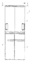
以下に本発明の実施形態を図面を参照して説明する。図1は一実施形態の冷蔵庫を示す正面図である。冷蔵庫1は断熱材から成るキャビネット70(図5参照)を有し、キャビネット70内が複数の仕切壁(不図示)で仕切られる。これにより、キャビネット70内の上部に冷蔵室2が配され、下部に野菜室3と冷凍室4とが左右に並設されている。冷蔵庫1本体の天井部となるキャビネット70の上方には、前面に吹出口9(図2参照)を有するイオン送出ユニット20が設けられている。
Embodiments of the present invention will be described below with reference to the drawings. FIG. 1 is a front view showing a refrigerator according to an embodiment. The refrigerator 1 has a cabinet 70 (see FIG. 5) made of a heat insulating material, and the inside of the
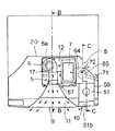
図2は図1のA−A断面図を示している。また、図3は図2のB−B断面図を示している。イオン送出ユニット20の背面右側には後方から外気を取り入れる吸込口8が形成される。吹出口9の後方には送風機6及び塵埃を捕集するフィルター7を内装したハウジング17が配される。
FIG. 2 shows a cross-sectional view taken along the line AA of FIG. FIG. 3 is a sectional view taken along line BB in FIG. A
図4はハウジング17の正面断面図である。送風機6は吸気口6a(図2参照)から軸方向に吸気して排気口6bから周方向に排気するシロッコファンから成っている。イオン送出ユニット20により居室内にイオンを送出できればよく、強い風力を必要としないため安価なシロッコファンを用いることができる。また、シロッコファンによってイオン送出ユニット20を薄く構成することができる。送風機6をシロッコファン以外の遠心ファン(ターボファン等)にしてもイオン送出ユニット20を薄く構成することができる。
FIG. 4 is a front sectional view of the
ハウジング17の一方側方には吸込口8に連通する空気流入口17aが形成される。フィルター7は空気流入口17aの近傍に配置され、フィルター7の下方から送風機6の下面の吸気口6a(図2参照)に空気が導かれるようになっている。送風機6の駆動によって空気流入口17aから流入する空気はフィルター7を上方から下方に通過し、吸気口6aから送風機6に流入して排気口6bから排気される。従って、イオン送出ユニット20内には吸込口8と送風機6の吸気口6aとの間を空気が流通する吸込側通風路12が形成される。尚、フィルター7は水を吸水して保水する保水性を有した部材(紙、織布、不織布等)から成っている。
An
図2、図3において、イオン送出ユニット20には送風機6の排気口6bから吹出口9に向かって前方へ行くほど左右方向に広がった吹出側通風路11が設けられる。吹出側通風路11の一方の側壁にはハウジング17に連結されるバイパス通路67が設けられている。バイパス通路67によって吹出側通風路11とフィルター7の上流側との間が連通する。
2 and 3, the
送風機6に近接した吹出側通風路11には、吹出側通風路11にイオンを放出するイオン発生装置5が設けられている。イオン発生装置5は電極(不図示)を有し、電極に高圧の交流電圧が印加されると、コロナ放電によって印加電圧が正電圧の場合は主としてH+(H2O)nから成るプラスイオンが生成され、負電圧の場合は主としてO2 -(H2O)mから成るマイナスイオンが生成される。ここで、n、mは整数である。
The blowing
H+(H2O)n及びO2 -(H2O)mは空気中の微生物等の浮遊菌の表面で凝集し、微生物等の浮遊菌を取り囲む。そして、式(1)〜(3)に示すように、衝突によって活性種である[・OH](水酸基ラジカル)やH2O2(過酸化水素)を微生物等の表面上で生成して浮遊菌の殺菌を行う。尚、n’、m’は整数である。 H + (H 2 O) n and O 2 − (H 2 O) m aggregate on the surface of airborne microorganisms such as microorganisms and surround the microorganisms. Then, as shown in the formulas (1) to (3), the active species [.OH] (hydroxyl radical) and H 2 O 2 (hydrogen peroxide) are generated and suspended on the surface of the microorganism or the like by collision. Disinfect bacteria. Note that n ′ and m ′ are integers.
H+(H2O)n+O2 -(H2O)m→・OH+1/2O2+(n+m)H2O ・・・(1)
H+(H2O)n+H+(H2O)n'+O2 -(H2O)m+O2 -(H2O)m'
→ 2・OH+O2+(n+n'+m+m')H2O ・・・(2)
H+(H2O)n+H+(H2O)n'+O2 -(H2O)m+O2 -(H2O)m'
→ H2O2+O2+(n+n'+m+m')H2O ・・・(3)
H + (H 2 O) n + O 2 − (H 2 O) m → OH + 1/2 O 2 + (n + m) H 2 O (1)
H + (H 2 O) n + H + (H 2 O) n ′ + O 2 − (H 2 O) m + O 2 − (H 2 O) m ′
→ 2 OH + O 2 + (n + n ′ + m + m ′) H 2 O (2)
H + (H 2 O) n + H + (H 2 O) n ′ + O 2 − (H 2 O) m + O 2 − (H 2 O) m ′
→ H 2 O 2 + O 2 + (n + n ′ + m + m ′) H 2 O (3)
従って、居室内にプラスイオンとマイナスイオンとを送出することによって浮遊菌の殺菌を行うことができる。また、電極の印加電圧を制御して居室内にマイナスイオンを送出するとリラクゼーション効果を得ることができる。尚、イオン発生装置5を通過する空気の湿度を検知する湿度センサー(不図示)が設けられている。
Accordingly, the floating bacteria can be sterilized by sending positive ions and negative ions into the room. In addition, a relaxation effect can be obtained by controlling the voltage applied to the electrode and sending negative ions into the room. A humidity sensor (not shown) for detecting the humidity of the air passing through the
イオン送出ユニット20の右側部には吸込口8から取り込まれた空気を加湿する加湿部50が設けられる。これにより、イオン発生装置5と、送風機6と、加湿部50とが、冷蔵庫1本体の天井部となるキャビネット70の上方に同一水平面内で配置される。この時、冷蔵庫1本体の横幅や奥行きの広さを利用して上記各部品を充分な広さや大きさにでき、各機能や性能を保つことができる。また、上記各部品をスペースに余裕をもって配列させることができる。従って、イオン送出ユニット20の高さを抑制して冷蔵庫1の内容積の減少を防止することができる。
A
加湿部50は貯水タンク51、水受け部64及びヒーター65を有している。イオン送出ユニット20の前面には加湿部50の前方に開口部10が設けられる。開口部10を介して貯水タンク51が前面から着脱自在になっている。水受け部64は吸込側通風路12の吸込口8と空気流入口17aとの間の下方に配されている。吸込口8から吸い込まれて吸込側通風路12を流通する空気を水受け部64で蒸発した水分により加湿するようになっている。
The
吸込口8から吸い込まれる空気は、冷蔵庫1本体の下部後方や上部に設けられる圧縮機や凝縮器による放熱で暖められる。或いは、冷蔵庫1本体の背面や側面の内側表面近くに設けられた放熱パイプによる放熱で暖められる。このため、該空気は室内空気よりも乾燥しているが、加湿によって水分子がイオンを充分に取り囲んだ状態で室内に放出できるようになる。
Air sucked from the
図5は図2のC−C断面図を示している。貯水タンク51は透明または半透明の樹脂やガラスから成り、把手部52が前部に取り付けられる。把手部52は樹脂成形品から成り、貯水タンク51に設けた凹部51aに爪部52aを嵌合して貯水タンク51の上下を挟持する。これにより、貯水タンク51及び把手部52がタンク組品として一体に着脱される。尚、把手部52と貯水タンク51とは接着剤による接着やインサート成形によって一体化される。把手部52及び貯水タンク51が樹脂から成る場合は超音波溶着してもよい。
FIG. 5 shows a cross-sectional view taken along the line CC of FIG. The
把持部52には前方に突出して下方に屈曲したL字型のリブ52bが形成される。リブ52bの上面前端には上方に突出する突起52cが形成される。加湿部50に装着された貯水タンク51は使用者により突起52c部を指先の腹側で引っ掛けて前方に少し引き出され、リブ52bの前面の背面側から手指を掛けて引き出すことができる。
The
把手部52の背面には開口部52dが形成される。開口部52dを介して貯水タンク51の水位を容易に視認でき、給水時期が使用者に解りやすくなっている。貯水タンク51の前部の一部を塞ぐように把手部52を設けても残りの部分から貯水タンク51の水位を容易に視認できるようになる。また、把手部52の上部には傾斜面63aを有するリブ63が設けられている。
An
貯水タンク51の略中央部の下面には給水時に脱着されるタンクキャップ53が設けられる。図6はタンクキャップ53近傍の詳細を示す側面断面図である。貯水タンク51に形成される給水用の開口部51bは円筒状の周壁51cが下方に突出し、タンクキャップ53は周壁51cに螺合される。タンクキャップ53と周壁51cの先端との間にはタンクパッキン57が挟まれて開口部51bがシールされている。
A
タンクキャップ53の中央部には貯水タンク51内に突出する円筒状の周壁53bを有した開口部53aが設けられる。開口部53aの中央には放射状の複数のリブ53dにより周壁53bに支持されたスリーブ53cが設けられる。スリーブ53cには弁ロッド55が挿通される。
An
貯水タンク51の外側に配される弁ロッド55の一端には押圧部55aが鍔状に形成される。押圧部55aとスリーブ53cの底面との間には圧縮バネ56が配される。貯水タンク51の内側に配される弁ロッド55の他端にはゴム等の可撓性部材から成るタンク弁54が鍔状に設けられる。
A
貯水タンク51を加湿部50から脱着した状態では、圧縮バネ56の付勢によってタンク弁54が開口部53aの周壁53bの先端に密接する。これにより、タンクキャップ53の開口部53aがシールされ、タンクキャップ53を下方に向けても漏水することはない。貯水タンク51を加湿部50に装着した状態では、加湿部50の底面に設けたリブから成る弁押し突起60が押圧部55aを押圧する。これにより、開口部53aが開放され、貯水タンク51内の水が水受け部64に流出するようになっている。
In a state where the
図5において、貯水タンク51は装着時に開口部10の上部に偏って加湿部50内に挿入される。この時、タンクキャップ53の下面が加湿部50の底部に突設したリブ59、61の上面59a、61aと摺動する。そして、タンクキャップ53がリブ61の傾斜面61bに摺動案内されて貯水タンク51が降下する。
In FIG. 5, the
この時、イオン送出ユニット20の上壁から下方に突設した突起62の傾斜面62aに貯水タンク51の後端が摺動して貯水タンク51は下方に案内される。また、把手部52のリブ63の傾斜面63aがイオン送出ユニット20の上壁前端と摺動して貯水タンク51が下方に案内される。加えて、タンクキャップ53の開口部の周壁53bに設けた傾斜面53e(図6参照)が弁押し突起60の傾斜面60a(図6参照)と摺動して貯水タンク51が下方に案内される。
At this time, the rear end of the
そして、把手部52がイオン送出ユニット20の上壁前端に当接して貯水タンク51がタンク弁54を開放する所定位置に設置される。この時、貯水タンク51の前部は把手部52が加湿部50の底面に当接し、後部は加湿部50の底面から上方に突出するリブ66に当接する。これにより、貯水タンク51が支持される。
Then, the
タンク弁54が開放される位置に配された貯水タンク51は前部のリブ63がイオン送出ユニット20の上壁下面に当接し、貯水タンク51の後部が突起62の下面に当接する。これにより、貯水タンク51の上下方向の位置が安定するとともに、水量の減少によって軽量になった貯水タンク51の、圧縮バネ56(図6参照)の付勢力による浮き上がりが規制されている。
In the
また、圧縮バネ56の付勢力を大きくしておくと、各当接部への押し付け力が増加する。これにより、貯水タンク51が軽量になった際に、冷蔵庫1本体の圧縮機による振動で貯水タンク51と突起62の下面との当接による異常音の発生する可能性が減少する。
Further, if the urging force of the
尚、リブ63及び傾斜面63aを貯水タンク51に設けてもよい。また、突起62の下面とリブ66との高さ方向の距離を貯水タンク51の高さよりも大きくするとよい。これにより、貯水タンク51を前方から挿入して突起62の下面に当接した際に、貯水タンク51とリブ66との間に隙間が形成される。従って、貯水タンク51を容易に所定位置に配することができる。
The
タンク弁54の開放により貯水タンク51から流出した水は水受け部64に溜められる。尚、リブ66に形成される開口部66aにより水受け部64の後部まで水が流入する。水受け部64が所定の水位Wになるとタンクキャップ53の開口部53a(図6参照)が水で密閉され、水の流出が停止される。
The water that flows out of the
水受け部64の底壁前端は後方が下がる傾斜部64aが形成される。これにより、水受け部64の貯水量を制限するとともに、詳細を後述するヒーター65を配した水受け部64の後方に水が流れやすくなっている。尚、傾斜部64aを水受け部64の前部の一部に設けてもよく、傾斜部64aをヒーター65付近まで延設してもよい。また、水受け部64はヒーター65が配される後部の面積を広くし、該後部とタンクキャップ53の下方との間を流路面積の狭い水路により形成してもよい。
The front end of the bottom wall of the
水受け部64は後部の底壁が上方に突出し、加湿部50の底面の外面に凹部64bを形成する。ヒーター65は凹部64b内に嵌めて設置されている。これにより、吸込側通風路12の空気流入口17aと吸込口8(図2参照)との間の下方にヒーター65が配される。ヒーター65の駆動によって水受け部64の水が昇温して蒸発する。
The
ヒーター65は凹部64bの上面に設置され、ヒーター65の下方とキャビネット70の上面との間に空間68が形成されている。これにより、ヒーター65の放熱を断熱し、冷蔵庫1の庫内への熱の侵入を低減することができる。水受け部64の全体の下面とキャビネット70との間に空間を形成してもよい。これにより、水受け部64内の水からの放熱を断熱することができる。
The
また、イオン送出ユニットの20の底壁には凹部64bに連通する通路71、72(図2参照)が形成される。通路71は凹部64bからイオン送出ユニット20の側面に延びて開口する。通路72は凹部64bから吸込口8の下方に延びて開口する。送風機6の駆動によって外気が通路71、空間68及び通路72を介して吸込口8からイオン送出ユニット20内に取り込まれる。これにより、ヒーター65の下面を冷却して断熱性が向上し、冷蔵庫1の庫内への熱の侵入をより低減することができる。
Further,
キャビネット70の上壁の断熱性が高い場合は凹部64bをキャビネット70の上壁に形成してヒーター65を設置してもよい。この時、ヒーター65の下方に空間68を設けるとキャビネット70側への熱の漏洩が減り、水受け部64の水を効率よく昇温することができる。
When the heat insulation of the upper wall of the
また、冷蔵庫1の冷凍サイクルのコンデンサ部を構成する放熱パイプをキャビネット70の上壁に埋設してもよい。これにより、放熱パイプの放熱が水受け部64の水を昇温するエネルギーの一部に使用され、ヒーター65の電力を削減して省電力化を図ることができる。
Further, a heat radiating pipe constituting the condenser part of the refrigeration cycle of the refrigerator 1 may be embedded in the upper wall of the
尚、ヒーター65に替えて超音波振動子を設けてもよい。超音波振動子は冷蔵庫1の制御回路等に設けた発振回路により超音波振動する。これにより、水受け部64内の水が振動して水面上に霧状に噴出し、水を昇温することができる。この時、超音波振動子付近から水受け部64内に水柱が発生する。水受け部64の高さが低いとイオン送出ユニット20の上壁に水柱が当って周辺に水滴が飛散する。このため、超音波振動子上方のイオン送出ユニット20上壁には上に凸となるU字状の返し部を設けると、水滴の飛散を低減することができる。
Note that an ultrasonic transducer may be provided in place of the
上記構成の冷蔵庫1において、貯水タンク51から水受け部64に供給された水はヒーター65により昇温され、一部が蒸発する。送風機6を駆動すると吸込口8からイオン送出ユニット20内に外気が取り入れられる。吸込口8から流入した空気は水受け部64で蒸発した水蒸気を含んで加湿される。
In the refrigerator 1 having the above-described configuration, the water supplied from the
加湿された空気はフィルター7により塵埃が除去される。また、フィルター7は空気に含まれる水分を吸水して保水する。これにより、フィルター7の通気抵抗が増加し、送風機6の負圧が全体に均一に加わる。その結果、フィルター7の上流が均一な層流状態になり、むら無く均等に加湿することができる。
Dust is removed from the humidified air by the
塵埃を除去した空気は吸気口6aを介して送風機6に軸方向から流入して排気口6bから周方向に排気される。送風機6から排気された空気は吹出側通風路11内を左右方向に広がりながら流通する。本実施形態では、吹出側通風路11の断面形状はイオン発生装置5上の高さが20mm以下で横幅が約60mmの矩形になっている。この時、冷蔵庫1本体の外気温が例えば25℃の場合に、イオン発生装置5上を通過する風速を1.75m/sec以下に設定しておくと、層流状態を維持できる。これにより、衝突によるイオンの消滅が低減され、イオン送出の効率を上げることができる。
The air from which the dust has been removed flows into the
また、送風機6の性能のバラツキ等を考慮してイオン発生装置5上を通過する風速を1.35m/sec以下に設定しておくと望ましい。これにより、外気温が0℃であっても安定して層流状態を維持できる。この時の風量は約5.8m3/hとなる。
Moreover, it is desirable to set the wind speed passing over the
外気温が25℃で相対湿度50%の場合に、圧縮機等を冷却した後に冷蔵庫下部の機械室から排出される排気空気の温度は約35℃まで上昇する。そして、該排気空気に対して水分の供給がないと、相対湿度が理論上約29%の乾燥した空気になる。その後、該排気空気は冷蔵庫1本体の背面を上昇する。 When the outside air temperature is 25 ° C. and the relative humidity is 50%, the temperature of the exhaust air discharged from the machine room below the refrigerator rises to about 35 ° C. after cooling the compressor and the like. If moisture is not supplied to the exhaust air, the air has a relative humidity of about 29% theoretically. Thereafter, the exhaust air rises on the back surface of the refrigerator 1 main body.
冷蔵庫1本体の背面を上昇する排気空気のみを吸込口8から吸い込んで加湿のないままイオン発生装置5の上方に供給されると、空気が乾燥しているため空気中の水分がイオンを取り囲んだ状態を多く作り出すことができなくなる。
When only the exhaust air that rises on the back of the refrigerator 1 main body is sucked from the
例えば、冷蔵庫1本体の両側面と該両側面に面した室内の壁面との隙間を15〜20mm程度にして、冷蔵庫1本体の背面を後方の室内の壁面に付けて配置すると、排気空気は冷蔵庫1本体の背面の両サイドを斜めにカットしたコーナー部から上昇する。該排気空気は冷蔵庫1本体の上面のイオン送出ユニット20上方を通って前方に排出される。この時、コーナー部を上昇した排気空気のみが吸込口8から吸い込まれた状態に近くなる。
For example, when the gap between both side surfaces of the refrigerator 1 main body and the wall surface of the room facing the both side surfaces is set to about 15 to 20 mm and the back surface of the refrigerator 1 main body is attached to the wall surface of the rear room, the exhaust air is stored in the refrigerator. Ascend from the corner part which cut both sides of the back of 1 main body diagonally. The exhaust air is discharged forward through the upper part of the main body of the refrigerator 1 and above the
コーナー部を上昇した排気空気の温度が35℃のままであれば、117g/hの水分を蒸発させて排気空気に供給すると相対湿度が約80%となる。これにより、空気中の水分がイオンを取り囲んだ状態を多く維持するための理想的な空気が得られることになる。 If the temperature of the exhaust air rising at the corner remains at 35 ° C., when the moisture of 117 g / h is evaporated and supplied to the exhaust air, the relative humidity becomes about 80%. As a result, ideal air for maintaining a large amount of moisture in the air surrounding the ions can be obtained.
イオン発生装置5を駆動すると、吹出側通風路11内にイオンが放出される。これにより、吹出側通風路11を流通する空気にイオンが含まれる。イオン発生装置5の上部を通過する空気は湿度センサーの検知によりヒーター65の通電が制御され、湿度40%〜90%に、望ましくは湿度60%〜90%に調整されている。
When the
尚、イオン発生装置5のイオン発生部5a付近の内部には、結露防止の通電による加熱部が設けられている。これにより、イオン発生部の結露によるイオンの発生効率の低下を防止している。そして、イオンを含んだ空気は奥行の長い吹出側通風路11を徐々に左右に広がって緩やかに流通し、吹出口9から左右に広がって居室内に送出される。
In addition, a heating unit by energization for preventing dew condensation is provided in the vicinity of the
図7に示すように、イオンiは水分子hにより周囲が取り囲まれる。この時、加湿部50による加湿を行わない場合は粒子径dが2〜3nmと推定されるが、加湿部50による加湿を行うと水分子hの数が増加して粒子径dが約18nmになると推定される。このため、空気中のカビ菌やウィルス等の浮遊菌とイオンiとが衝突する度合が高くなる。
As shown in FIG. 7, the periphery of the ion i is surrounded by water molecules h. At this time, when humidification by the
また、空気中の塵埃にイオンiが衝突した際に、イオンiは水分子hに保護され消滅が低減される。従って、充分な量のイオンが居室内に拡散して送出され、殺菌効果やリラクゼーション効果を得ることができるとともに、室内の浮遊菌を迅速に除去することができる。 Further, when the ions i collide with dust in the air, the ions i are protected by the water molecules h, and disappearance is reduced. Therefore, a sufficient amount of ions are diffused and sent out into the room, so that a sterilization effect and a relaxation effect can be obtained, and airborne bacteria in the room can be quickly removed.
また、吹出側通風路11を流通する空気はバイパス通路67を介してフィルター7に導かれる。これにより、プラスイオン及びマイナスイオンがフィルター7及び送風機6を通過し、フィルター7及び送風機6を滅菌して清潔に保つことができる。バイパス通路67を吸込口8付近に連結してもよい。これにより、加湿部50等の吸込口8とフィルター7との間を滅菌して清潔に保つことができる。
Further, the air flowing through the blowout
本実施形態によると、加湿部50により加湿した空気にイオンを含んで送出するので、イオンが水分子に囲まれて衝突によるイオンの減少を抑制することができる。また、イオン発生装置5から発生するオゾンの量が加湿により減少するとともに、発生したオゾンが水分により消滅しやすくなる。これにより、居室内に送出されるプラスイオンとマイナスイオンを居室内に充分行き渡らせて滅菌効果を向上させることができる。また、オゾン量を減少してオゾンの臭気による不快感を和らげることができる。
According to the present embodiment, since the ions are contained in the air humidified by the
尚、イオン発生装置を通過する空気の湿度を40%〜90%にすると、イオンの消失を低減してイオンを効率よく存在させることができる。 In addition, when the humidity of the air which passes an ion generator shall be 40%-90%, the loss | disappearance of ion can be reduced and ion can exist efficiently.
また、従来のように居室内全体を加湿する加湿器を設ける必要がなく、大きな加湿能力を必要としないため、省電力化を図ることができる。更に、加湿器内の送風機との衝突によるイオンの消失や、該送風機で空気が撹拌されてイオン同士が衝突することによるイオンの消失を防止することができる。このため、居室内に充分な量のイオンを供給することができる。 In addition, it is not necessary to provide a humidifier for humidifying the entire living room as in the prior art, and a large humidification capability is not required, so that power saving can be achieved. Furthermore, the loss | disappearance of the ion by collision with the air blower in a humidifier, and the loss | disappearance of the ion by the air being stirred with this air blower and colliding ions can be prevented. For this reason, a sufficient amount of ions can be supplied into the living room.
加えて、奥行の長い冷蔵庫1の天井部の後部に送風機6を配置し、左右に広がる吹出側通風路11を介して吹出口9から空気を送出するので、イオンを含む空気が左右方向に広がって送出され、居室内にイオンを充分拡散することができる。
In addition, since the
本実施形態において、ヒータ65の加熱により水受け部64の水を蒸発させて加湿しているが、他の方法で加湿してもよい。例えば、ヒータ65を省いて水受け部64に浸漬される布等の保水部材をフィルター7に連結してもよい。これにより、水の表面張力で保水部材及びフィルター7に水分が供給され、フィルター7を通過する空気を加湿することができる。
In the present embodiment, the water in the
また、ヒーター65を水受け部64の底面に設けているが、水受け部64の側面周辺にアルミ箔ヒーター等の平面状のヒーターを設けてもよい。図8はアルミ箔ヒータの一例を示す平面図である。アルミ箔ヒータ70はコードヒータ71が熱伝導板72に固着されている。コードヒータ71は電熱線を巻き付けた芯材を絶縁体で被覆して形成され、可撓性を有している。これにより、水受け部64の側面の広い範囲に省スペースでヒータを取り付けることができるとともに、ヒーターから冷蔵庫1の庫内に伝えられる熱量を少なくすることができる。
Further, although the
また、イオン発生装置5の電極部を針状電極にしてもよい。図9は針状電極を有するイオン発生装置を示す斜視図である。イオン発生装置80は、電源部81にリード部82を介して電極部83が接続される。電極部83は針状の針状電極が平板状の平板部82bから突設されている。電源部81の駆動により電極部83に電圧が印加され、針状電極83aの先端からプラズマ放電してイオンが発生する。
Moreover, you may make the electrode part of the
電極部83は針状電極83aの先端を上方に向けて吹出側通風路11内に設置される。これにより、高湿度雰囲気で電極部83に発生する結露が針状電極83aの先端に発生しにくくなるとともに発生した結露が流下し易くなる。従って、結露によるイオン発生量(特にプラズマ放電によるイオン発生量)の減少を防止することができる。
The
尚、イオン発生装置5に接続してイオンを放出する電極を冷蔵室2内または野菜室3内に設けてもよい。これにより、部品点数の増加を抑制してイオン発生装置5により印加電圧を制御して冷蔵室2や野菜室3内の殺菌を行うことができる。
In addition, you may provide the electrode which connects with the
1 冷蔵庫
2 冷蔵室
3 野菜室
4 冷凍室
5、80 イオン発生装置
6 送風機
7 フィルター
8 吸込口
9 吹出口
10 開国部
11 吹出側通風路
20 イオン送出ユニット
50 加湿部
51 貯水タンク
51a 開口部
52 把手部
53 タンクキャップ
53a 開口部
54 タンク弁
55 弁ロッド
60 弁押し突起
64 水受け部
65 ヒータ
67 バイパス通路
70 アルミ箔ヒータ
83 電極部
83a 針状電極
DESCRIPTION OF SYMBOLS 1
Claims (3)
前記送風機は遠心ファンから成り、前記イオン発生装置と、前記送風機と、前記加湿部とを同一水平面内に配置し、
前記イオン発生装置は先端を上方に向けた針状の電極を有し、
前記電極に高圧の交流電圧が印加されてコロナ放電によって生成されたH + (H 2 0) n から成るプラスイオンとO 2 - (H 2 O) m から成るマイナスイオンとが空気中に放出され、
空気中の水分子により前記プラスイオン及び前記マイナスイオンの周囲が取り囲まれて粒子が形成され、
前記プラスイオン及び前記マイナスイオンの周囲の水分子の数が前記加湿部による加湿によって増加して前記粒子の外径が大きくなり、
外径が大きくなった前記粒子は前記吹出側通風路を左右方向に広がって流通して前記吹出口から室内に送出されることを特徴とする冷蔵庫。 An air outlet that is arranged on the ceiling of the main body and opens to the front surface, a blower that is arranged behind the air outlet and takes in outside air from the air inlet and sends it out from the air outlet, and the air outlet and the air outlet A blowout side ventilation path that expands in the left-right direction as it goes forward, an ion generator that releases ions to the blowout side ventilation path, and an air that is installed on the intake side of the blower and flows into the blowout side ventilation path A humidifying part for humidifying
The blower is composed of a centrifugal fan, and the ion generator, the blower, and the humidification unit are arranged in the same horizontal plane ,
The ion generator has a needle-like electrode with the tip facing upward,
Positive ions composed of H + (H 2 0) n and negative ions composed of O 2 − (H 2 O) m generated by corona discharge when a high-voltage alternating voltage is applied to the electrodes are released into the air. ,
The positive ions and the negative ions are surrounded by water molecules in the air to form particles,
The number of water molecules around the positive ions and the negative ions is increased by humidification by the humidifying part, and the outer diameter of the particles is increased,
The refrigerator , wherein the particles having an increased outer diameter are circulated in the left-right direction through the blow-out side ventilation passage and are sent into the room from the blow-out port .
3. The refrigerator according to claim 1, wherein a bypass passage is provided that branches from the blow-out side ventilation passage and communicates the downstream side of the ion generator and the upstream side of the blower.
Priority Applications (1)
| Application Number | Priority Date | Filing Date | Title |
|---|---|---|---|
| JP2006154330A JP4716927B2 (en) | 2006-06-02 | 2006-06-02 | refrigerator |
Applications Claiming Priority (1)
| Application Number | Priority Date | Filing Date | Title |
|---|---|---|---|
| JP2006154330A JP4716927B2 (en) | 2006-06-02 | 2006-06-02 | refrigerator |
Publications (3)
| Publication Number | Publication Date |
|---|---|
| JP2007322090A JP2007322090A (en) | 2007-12-13 |
| JP2007322090A5 JP2007322090A5 (en) | 2008-10-16 |
| JP4716927B2 true JP4716927B2 (en) | 2011-07-06 |
Family
ID=38855065
Family Applications (1)
| Application Number | Title | Priority Date | Filing Date |
|---|---|---|---|
| JP2006154330A Expired - Fee Related JP4716927B2 (en) | 2006-06-02 | 2006-06-02 | refrigerator |
Country Status (1)
| Country | Link |
|---|---|
| JP (1) | JP4716927B2 (en) |
Families Citing this family (4)
| Publication number | Priority date | Publication date | Assignee | Title |
|---|---|---|---|---|
| MY157580A (en) | 2008-08-28 | 2016-06-30 | Sharp Kk | Ion generating apparatus and air purifying apparatus |
| JP4406673B1 (en) | 2008-08-28 | 2010-02-03 | シャープ株式会社 | Ion generator and air purifier |
| MY152662A (en) * | 2009-04-16 | 2014-10-31 | Sharp Kk | Ion generating apparatus and air cleaner |
| KR101803628B1 (en) | 2016-02-16 | 2017-12-28 | 엘지전자 주식회사 | refrigerator |
Citations (4)
| Publication number | Priority date | Publication date | Assignee | Title |
|---|---|---|---|---|
| JP2002286240A (en) * | 2001-03-23 | 2002-10-03 | Toshiba Kyaria Kk | Air conditioner |
| JP2002286356A (en) * | 2001-03-28 | 2002-10-03 | Mitsubishi Electric Corp | Negative ion and ozone generator |
| JP2005214463A (en) * | 2004-01-28 | 2005-08-11 | Sharp Corp | Refrigerator |
| JP2006057941A (en) * | 2004-08-20 | 2006-03-02 | Sharp Corp | Air conditioner |
Family Cites Families (2)
| Publication number | Priority date | Publication date | Assignee | Title |
|---|---|---|---|---|
| JP3479345B2 (en) * | 1994-08-02 | 2003-12-15 | 高砂熱学工業株式会社 | Method and apparatus for removing gaseous impurities present in air |
| JP3577623B2 (en) * | 1998-05-07 | 2004-10-13 | 三菱電機株式会社 | Air cleaner |
-
2006
- 2006-06-02 JP JP2006154330A patent/JP4716927B2/en not_active Expired - Fee Related
Patent Citations (4)
| Publication number | Priority date | Publication date | Assignee | Title |
|---|---|---|---|---|
| JP2002286240A (en) * | 2001-03-23 | 2002-10-03 | Toshiba Kyaria Kk | Air conditioner |
| JP2002286356A (en) * | 2001-03-28 | 2002-10-03 | Mitsubishi Electric Corp | Negative ion and ozone generator |
| JP2005214463A (en) * | 2004-01-28 | 2005-08-11 | Sharp Corp | Refrigerator |
| JP2006057941A (en) * | 2004-08-20 | 2006-03-02 | Sharp Corp | Air conditioner |
Also Published As
| Publication number | Publication date |
|---|---|
| JP2007322090A (en) | 2007-12-13 |
Similar Documents
| Publication | Publication Date | Title |
|---|---|---|
| JP5899453B2 (en) | Ozone / ion generator for generating ozone and ion wind and air conditioner equipped with the same | |
| JP2008036257A (en) | Air cleaner | |
| JP3995491B2 (en) | Air conditioner | |
| JP2011237139A (en) | Air conditioner | |
| JP4716927B2 (en) | refrigerator | |
| JP2010276296A (en) | Humidifier | |
| JP2007051866A (en) | Air conditioner | |
| JP4007817B2 (en) | Air conditioner | |
| JP2013079755A (en) | Ion delivery device and air conditioner with the same | |
| JP2013213454A (en) | Blower | |
| JP5037663B2 (en) | refrigerator | |
| JP2004293893A (en) | Air conditioner | |
| JP6480700B2 (en) | Air blower | |
| JP2007017150A (en) | Air conditioner | |
| JP5452757B2 (en) | Blower | |
| JP2002089868A (en) | Air conditioner | |
| JP2003106578A (en) | Humidifying device and electric heater having the device | |
| JP2013221631A (en) | Blower device | |
| JP2002243243A (en) | Air conditioner | |
| JP2010276227A (en) | Humidifying device | |
| CN207262559U (en) | Air conditioner | |
| WO2014030539A1 (en) | Air conditioner | |
| JP2003120972A (en) | Air cleaner or air conditioner | |
| JP2002228180A (en) | Air conditioner | |
| JP2014031897A (en) | Refrigerator |
Legal Events
| Date | Code | Title | Description |
|---|---|---|---|
| RD01 | Notification of change of attorney |
Free format text: JAPANESE INTERMEDIATE CODE: A7421 Effective date: 20071121 |
|
| A521 | Written amendment |
Free format text: JAPANESE INTERMEDIATE CODE: A523 Effective date: 20080903 |
|
| A621 | Written request for application examination |
Free format text: JAPANESE INTERMEDIATE CODE: A621 Effective date: 20080903 |
|
| A977 | Report on retrieval |
Free format text: JAPANESE INTERMEDIATE CODE: A971007 Effective date: 20100318 |
|
| A131 | Notification of reasons for refusal |
Free format text: JAPANESE INTERMEDIATE CODE: A131 Effective date: 20100420 |
|
| A521 | Written amendment |
Free format text: JAPANESE INTERMEDIATE CODE: A523 Effective date: 20100617 |
|
| A02 | Decision of refusal |
Free format text: JAPANESE INTERMEDIATE CODE: A02 Effective date: 20101109 |
|
| A521 | Written amendment |
Free format text: JAPANESE INTERMEDIATE CODE: A523 Effective date: 20110208 |
|
| A911 | Transfer of reconsideration by examiner before appeal (zenchi) |
Free format text: JAPANESE INTERMEDIATE CODE: A911 Effective date: 20110216 |
|
| TRDD | Decision of grant or rejection written | ||
| A01 | Written decision to grant a patent or to grant a registration (utility model) |
Free format text: JAPANESE INTERMEDIATE CODE: A01 Effective date: 20110329 |
|
| A01 | Written decision to grant a patent or to grant a registration (utility model) |
Free format text: JAPANESE INTERMEDIATE CODE: A01 |
|
| A61 | First payment of annual fees (during grant procedure) |
Free format text: JAPANESE INTERMEDIATE CODE: A61 Effective date: 20110329 |
|
| R150 | Certificate of patent or registration of utility model |
Free format text: JAPANESE INTERMEDIATE CODE: R150 |
|
| FPAY | Renewal fee payment (event date is renewal date of database) |
Free format text: PAYMENT UNTIL: 20140408 Year of fee payment: 3 |
|
| LAPS | Cancellation because of no payment of annual fees |